

Centrometal El-Cm Compact 18, El-Cm Compact 6, El-Cm Compact 21, El-Cm Compact 12, El-Cm Compact 15 Technical Manual
...Page 1
TECHNICAL MANUAL
for assembling, use and maintenance
of the electric boiler
and additional equipment
TUELCMC-03/2010-eng
El-Cm Compact
HEATING TECHNIQUE
Centrometal d.o.o. - Glavna 12, 40306 Macinec, CROATIA, tel: +385 40 372 600, fax: +385 40 372 611
Page 2
2
Technical data
Technical manual El-Cm Compact
410
280
100230
1
0
830
860
450270
TEHNIKA GRIJANJA
P
64
Digital modulating
regulation
Main switch
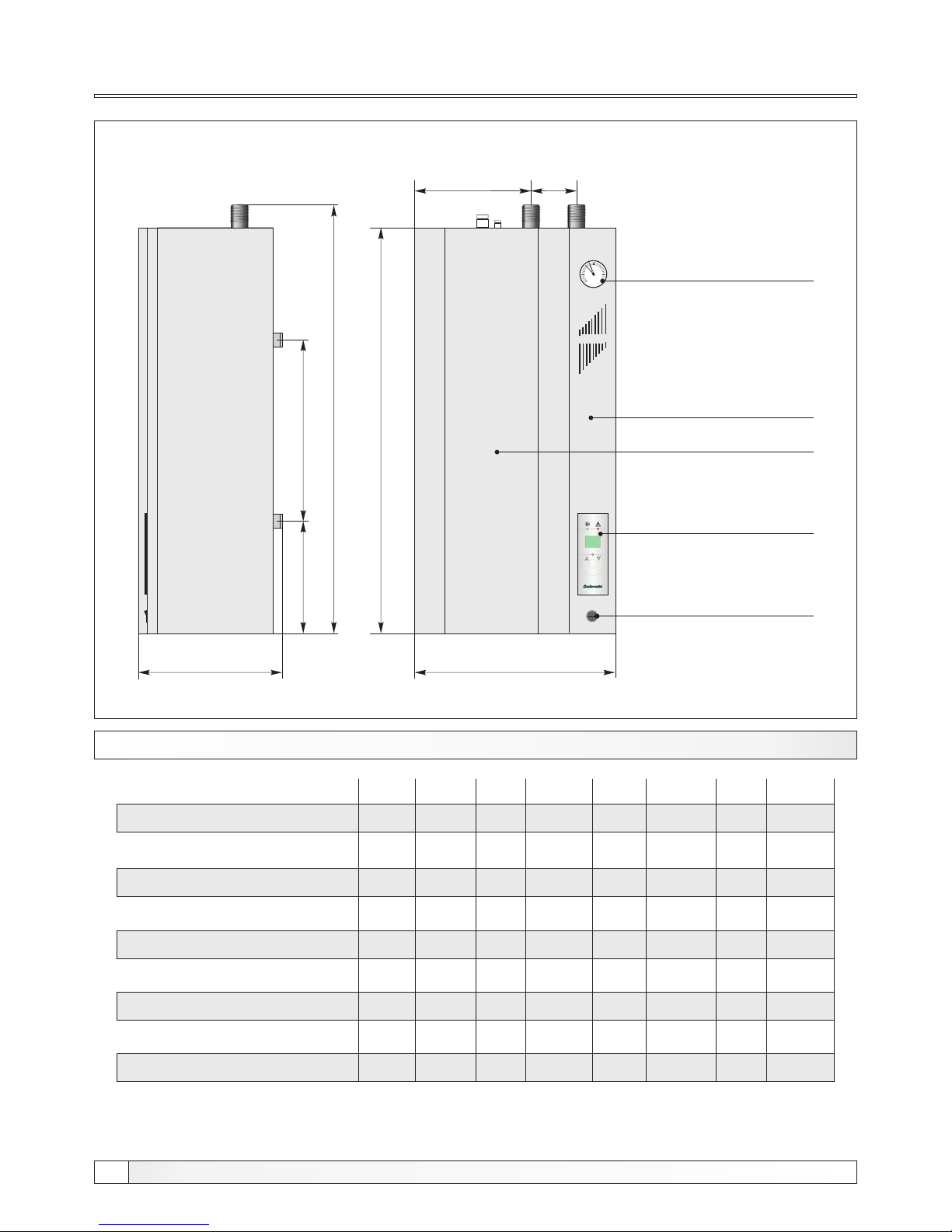
Picture 1. - Basic technical dimensions of the electrical boiler El-Cm Compact
TECHNICAL DATA
Front cover
Console of the regulation
3
1
2
4
0
bar
Manometar
El-Cm
C
o
m
p
a
c
t
(kW)
(lit.)
(kg)
(bar)
(MPa)
(kW)
2
(mm )
(lit.)
(R)
6
12
39
3
0,3
2x3
5x2,5
10
1"
El-Cm Compact
9
12 1815 21
246
9
12
40
3
0,3
3+6
5x2,5
10
1"
12
12
40
3
0,3
2x6
5x4
10
1"
15
12
41
3
0,3
2x6+3
5x4
10
1"
18
12
41
3
0,3
3x6
5x6
10
1"
21
12
42
3
0,3
3x6+3
5x6
10
1"
24
12
42
3
0,3
4x6
5x6
10
1"
27
27
12
42
3
0,3
4x6,75
5x6
10
1"
Nom.thermal output
Capacity
Electric boiler mass
Max. operating press.
Max. operating press.
Electric heater
Conductor thickness
Expansion vessel
Inlet/Outlet
Page 3
3
Essential parts
Technical manual El-Cm Compact
Inlet
Outlet
Wire introducer (room thermostat)
Wire introducer (power supply)
Regulation box
Microswitch
Sensor probe
Pressure switch
Boiler
Safety thermostat
Electric heater
Expansion vessel
Circulation pump
Boiler porter
Thermal insulation
Boiler body
Boiler casing
Filling/Draining
Security valve
Electric heaters
L2L1L3N 1 2 3
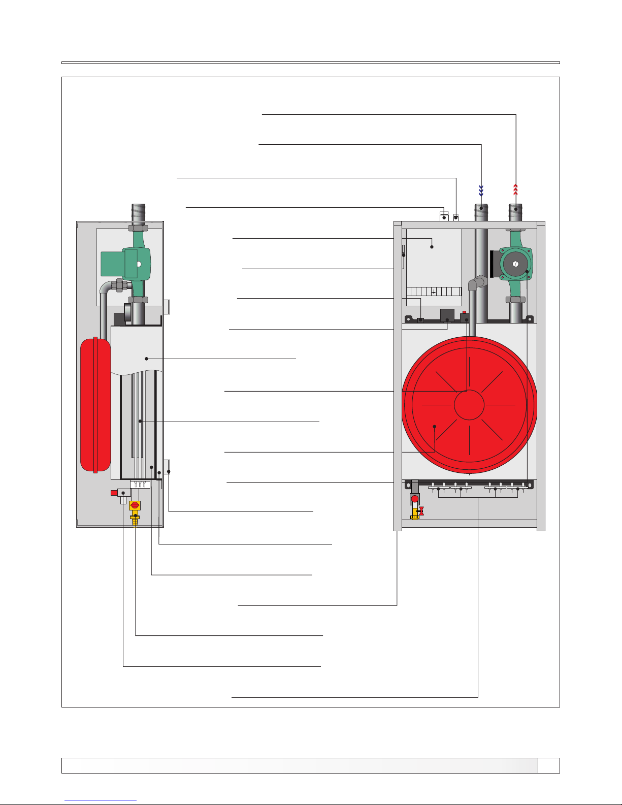
Picture 2. - Essential parts of the electric boiler El-Cm Compact
Page 4
4
Boiler description
Technical manual El-Cm Compact
Hot water electric boiler El-Cm Compact has a modern design and is constructed out of certified
high quality materials by applying most modern robot welding technology, it is certified according
to domestic and international norms and is therefore suitable for connection to central heating
system installation.
We suggest you to follow carefully all instructions of this manual, in order Your electric boiler could
operate properly for a long time.
We do not take the responsibility for eventual printing errors in this manual. In any case we have
the right to change instructions for use of its own products if necessary and useful.
The El-Cm Compact electric boilers series is engineered and produced for heating of smaller
premises or flats with a nominal thermal output of 6 to 27 kW as an independent energy source.
Their modern design and minimal dimensions enable us to put them on various places of our
house or flat.
3.0. INTEGRAL PARTS OF THE ELECTRIC BOILER El-Cm Compact
BOILER
Is made of high quality steel sheet, welded by applying most modern robot welding technology
and certified under the pressure of 6 bar. Surface is coated by high quality basic colour.
MAIN SWITCH
The purpose of the main switch is to turn on and off the electric boiler power supply.
FRONT COVER
The front cover is attached to the boiler casing with 4 screw (2 piece on the upper and 2 pieces on
the lower part of the electric boiler). By removing the front cover You are enable to approach to the
main parts of the electric boiler and the micro switch are activated. Micro switch turn off the
operation of the regulation, but the power supply to the boiler is not disconnect.
INLET
The inlet tube (1”) with an integrated circulation pump is marked by the red coloured sticker and is
placed on the upper right side of the electric boiler.
1.0. INTRODUCTION
2.0. PURPOSE
Page 5

5
Boiler parts
Technical manual El-Cm Compact
OUTLET
The outlet tube (1”) is marked by the blue coloured sticker and is placed on the upper left side of the
electric boiler. It is inserted through the whole length of the electric boiler till its deepest point in order
to spread the cooled water inside the electric boilers body and over the electric heater/heaters.
SENSOR PROBE
On the upper side of the electric boiler is placed sensor probe of the boiler regulation.
SAFETY THERMOSTAT
Overlie security thermostat is situated on the upper side of the boiler, by the pressure switch, when it
is activated it turn off the boiler power supply.
ELECTRIC HEATERS
Electric heaters are situated on the lower part of the electric boiler. Their capacity depends on the
total maximal capacity of the electric boiler.
THERMAL INSULATION
The electric boiler is insulated with mineral wool insulation coating, thickness is 30 mm and is
placed on the aluminium-foil, which prevents losses of heat through convection and radiation.
FILLING - DRAINING / SAFETY VALVE
On the lower part of the electric boiler there is a sealed filling-draining cock for the boiler and the
whole system, as well as certified security valve with an opening pressure of 2,5 bar.
CIRCULATION PUMP / EXPANSION VESSEL
The electric boiler is also supplied by a circulation pump situated on the upper side of the boiler
connected to the inlet, as well as by an expansion vessel situated on the outlet.
PRESSURE SWITCH
In case of pressure loss, the pressure switch turns off the boiler regulation to prevent the operating
of the electric boiler without water, but the power supply to the boiler is not disconnect.
MICRO SWITCH
In case the cover of the electric boiler has been opened, micro switch turn off the operation of the
boiler regulation, but the power supply to the boiler is not disconnect.
BOILER REGULATION
The boiler regulation steers the electric heaters and pump operation and is situated on the console
of the boiler regulation on the right side of the electric boiler.
Page 6
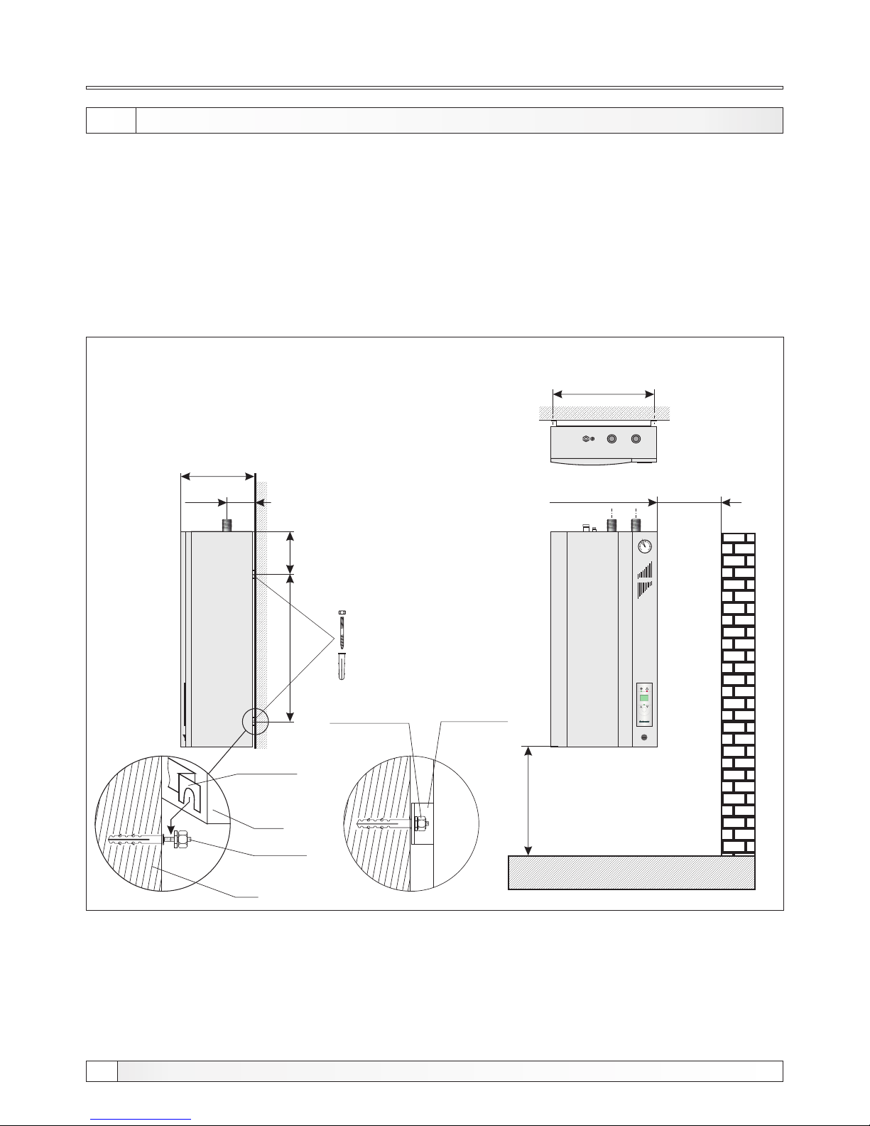
6
Installation of electric boiler
Technical manual El-Cm Compact
4.0. INSTALLATION OF ELECTRIC BOILER
The El-Cm Compact electric boiler is aimed to be hanged on the wall. For the easier setting on the
wall, there is a hanging console on its back part which is to be hanged on wall metal dowels of M10
type or even stronger. Electric boiler has to be hanged on the height of min. 0,6 m from the floor,
because of the eventual electric heater exchange. The distance of the side wall has to be min 0,3
m, in order to easier the approach to the boiler. The electric boiler has to be positioned on the
lowest point of the whole installation. If there is a lack of space and therefore the electric boiler has
to be installed on the highest point, an airvent vessel has to be connected on its exit point with a
minimum of water content (cca. 1 lit.). This vessel has to be connected with an airvent pot. We
suggest the connection to be executed by the authorized person.
min. 300 mm
388
290
100
450
TEHNIKA GRIJANJA
P
1
0
64
267
min. 600 mm
Picture 3. - Installation of the electric boiler El-Cm Compact on the wall
Boiler porter
(on the back
side of the
boiler)
Screw M8
Wall
Boiler
After putting the
electric boiler on
the porters,
fasten the
nuts
Boiler porter
(on the back
side of the
boiler)
3
1
2
4
0
bar
El-Cm
C
o
m
p
a
c
t
Page 7
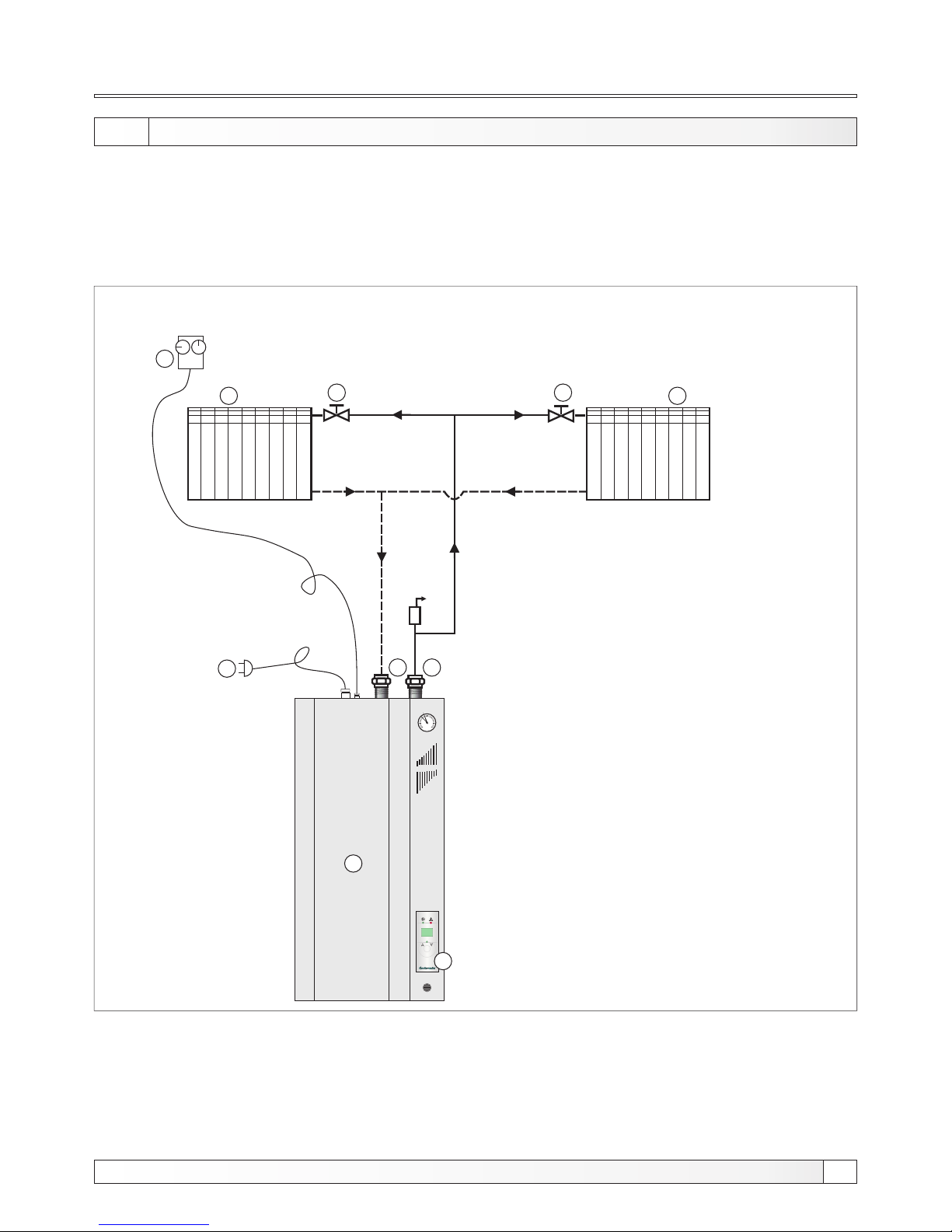
7
Technical manual El-Cm Compact
Connecting to tube installation of the central heating system and the start-up of the electric boiler
has to be executed considering all technical standards and norms, on behalf of the authorized
person, who is able to take over the responsibility.
Depending of the size of the space, which we would like to be heated, its purpose and heat losses,
the proper capacity of the electric boiler has to be chosen.
5.0. CONNECTING THE El-Cm Compact TO THE CENTRAL HEATING SYSTEM
1. Electric boiler El-Cm Compact
2. Digital regulation
3. Radiator
4. Valve
5. Removable (holender) connection
6. Room thermostat
7. Power supply
P
1
0
64
1
2
4
4
5
6
3
7
Picture 4. - Principle scheme for the connection of the electric boiler El-Cm Compact to the
installation of central heating system
3
5
Connecting to the central heating system
3
1
2
4
0
bar
El-Cm
C
o
m
p
a
c
t
Page 8
8
Electric connection
Technical manual El-Cm Compact
6.0. CONNECTION TO THE ELECTRICAL POWER NET
6.1. SAFETY THERMOSTAT
Safety thermostat is mounted on the upper side of the electric boiler, under the regulation box. It
disconnect the electric boiler operation if the boiler temperature achieve 93°C. When we start
again the operation of the electric boiler, it is obligatory to wait until the boiler temperature fail
below 70°C, then we take off the boiler cover which is fasten with 4 screws (2 screws on the upper
side and 2 screws on the lower side) and push the red push-button on the safety thermostat. If this
failure in the electric boiler operation happens frequently please call the authorised person for the
control.
6.2. CONNECTION OF THE ROOM THERMOSTAT
The electric boilers El-Cm Compact are provided by the ordinaly terminals (1 and 2) for the
connection with the room thermostat. The bridge is prewired on the ordinaly terminal (1 and 2) for
the case if the room thermostat is not used. If we intend to connect it, we should know which kind of
room thermostat shall be connected. Simple versions of the room thermostat are connected
serial, inside the steering tension circuit, i.e. to the terminal no. 1. - room thermostat supply and
the antiphase back to the terminal no. 2. More sophisticated room thermostats with a signal light
or with an integrated temperature simulation system, which require to be constantly under tension
are to be connected to the terminals 1 and 2.
All connections to the electrical power net have to be executed in compliance with all norms and
standards by an authorized person. The electric boiler is completely prewired. All additional
connections (electric boiler supply, room thermostat) are aimed to be connected through the
ordinaly terminal on the upper left side of the device, under the front cover of the electric boiler.
The electric power supply of the electric boiler is connected by means of an PGP cable with an
adequate thickness, which has to be inserted through the hole on the upper left side of the electric
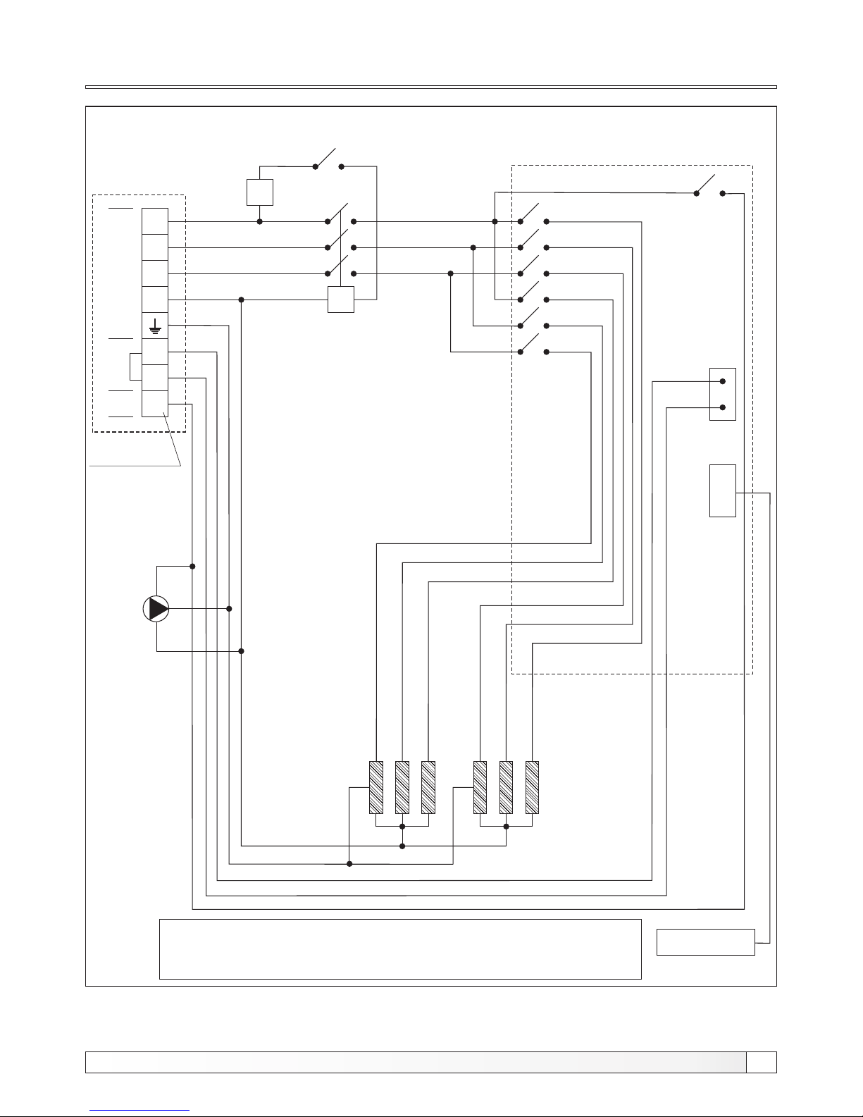
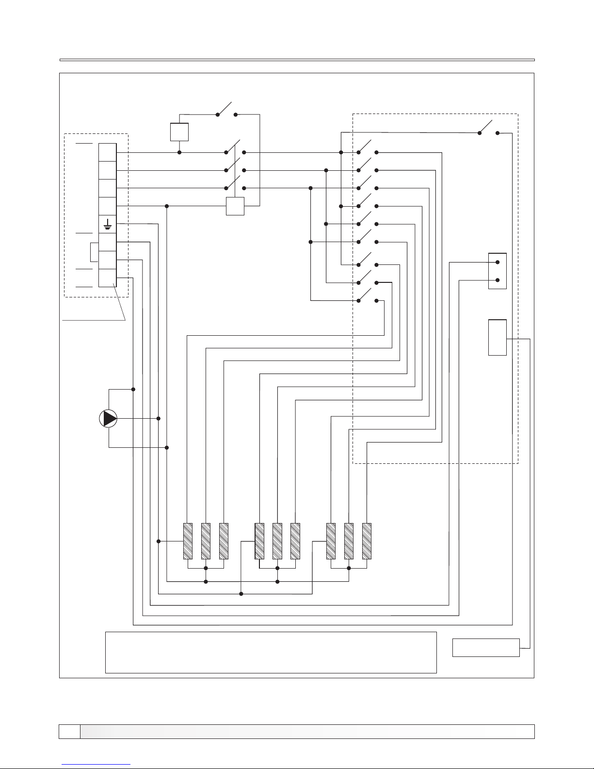
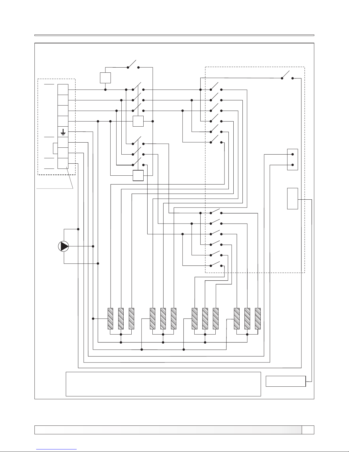
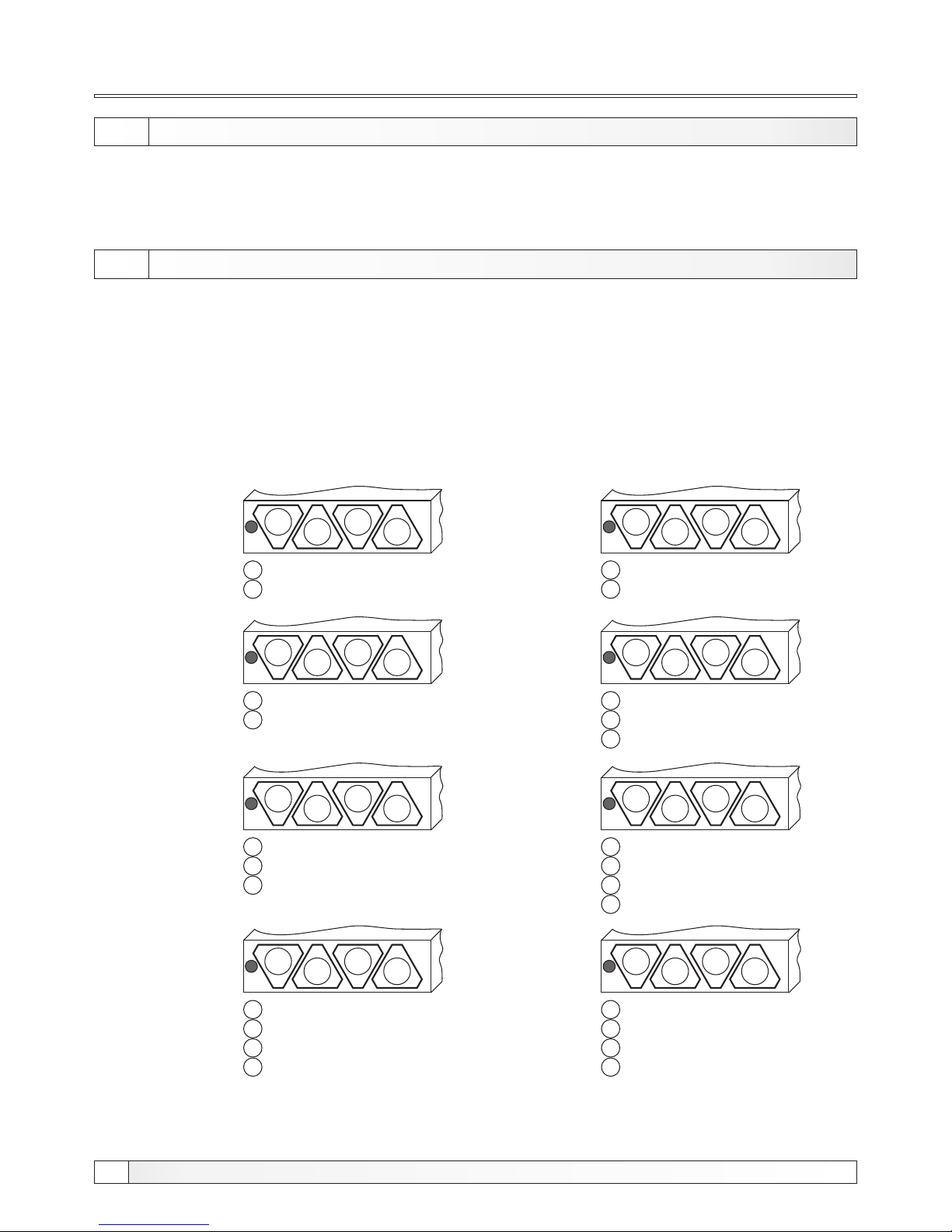
boiler and connected to the terminal marked with L , L , L , N, . Electric scheme is displayed on
1 2 3
the scheme 1, 2 and 3.
The instructions shall state that means for disconnection must be incorporated in the fixed wiring
in accordance with the wiring rules.
This appliance is not intended for use by persons (including children) with reduced physical,
sensory or mental capabilities, or lack of experience and knowledge, unless they have been given
supervision or instruction concerning use of the appliance by a person responsible for their safety.
Children should be supervised to ensure that they do not play with the appliance.
Do not switch on if there is a possibility that the water in the heater is frozen.
Page 9
9
Electric scheme
Technical manual El-Cm Compact
Connection
voltage
3x400V
Scheme 1. - Electric scheme of the El-Cm Compact 6-12 kW (3-phase connection)
REGULATION
PANEL
Ordinaly terminal
P - main switch
ST - safety thermostat
K - contactor
K - contactor 1
1
EG - electric-heater
RE - electronic of regulation
LEGEND:
ST
K
L
1
L
2
L
3
N
1
2
EG EG EG
P
Room
thermostat
EG EG EG
3
Pump
LED-DISPLAY
RE
Page 10
Electric scheme
Scheme 2. - Electric scheme of the El-Cm Compact 15-18 kW (3-phase connection)
10
Technical manual El-Cm Compact
ST
K
L
1
L
2
L
3
N
1
2
EG EG EG EG EG EGPEG EG EG
3
LED-DISPLAY
RE
REGULATION
PANEL
Connection
voltage
3x400V
Room
thermostat
Pump
Ordinaly terminal
P - main switch
ST - safety thermostat
K - contactor
K - contactor 1
1
EG - electric-heater
RE - electronic of regulation
LEGEND:
Page 11
11
Technical manual El-Cm Compact
Electric scheme
Connection
voltage
3x400V
Scheme 3. - Electric scheme of the El-Cm Compact 21-27 kW (3-phase connection)
REGULATION
PANEL
Ordinaly terminal
P - main switch
ST - safety thermostat
K - contactor
K - contactor 1
1
EG - electric-heater
RE - electronic of regulation
LEGEND:
Room
thermostat
Pump
ST
K
L
1
L
2
L
3
N
1
2
EG EG EG EG EG EG
P
K
1
EG EG EG EG EG
3
LED-DISPLAY
RE
EG
Page 12
12
Technical manual El-Cm Compact
Replacement of the el. heaters
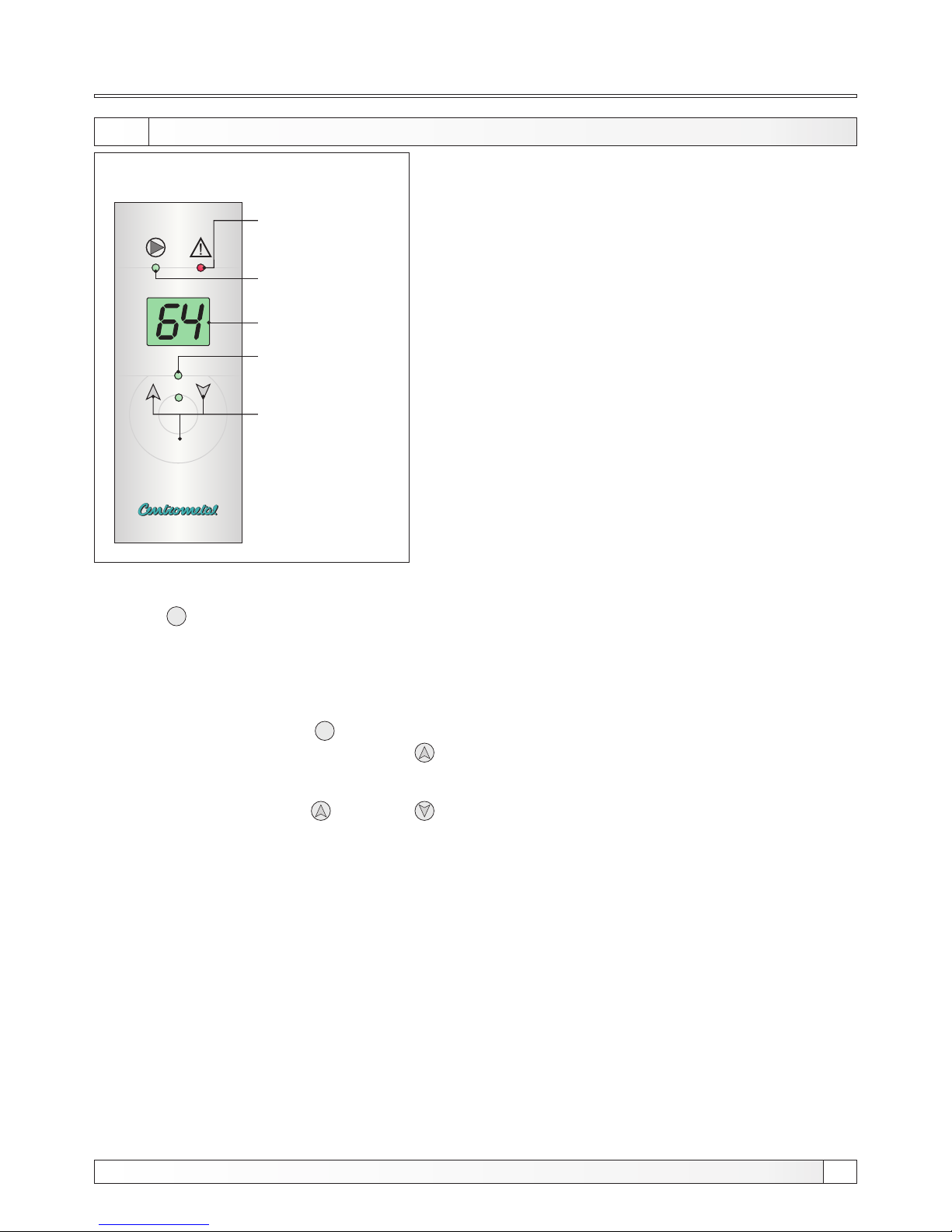
8.0. REPLACEMENT OF THE ELECTRIC HEATER
Before You take off the front cover it is necessary to disconnect the power supply. Then we take off the
front cover and lower side of the casing (which are fasten with the screws). Before we take off the
electric heater it is necessary to empty the electric boiler with water and disconnect the wires from the
el. heater. When You put on the new electric heater it is necessary to seal it, connect the wires to the
electric heater and attach the lower side of the cover and front cover with the screws back on the
place.
7.0. TECHNICAL DATA
- tension:.............................................................................................400V / 50Hz
- el. boiler steering mode:.....................................................modulating regulation
- electronic part consumption:...............................................................max. 10 VA
- regulation area:........................................................................................20-85°C
Position of electrical heaters on the bottom side of boiler.
24 kW
1 = 3 x 2.000 W
2 = 3 x 2.000 W
3 = 3 x 2.000 W
4 = 3 x 2.000 W
1
2
3
4
27 kW
1 = 3 x 2.250 W
2 = 3 x 2.250 W
3 = 3 x 2.250 W
4 = 3 x 2.250 W
1
2
3
4
18 kW
1 = 3 x 2.000 W
2 = 3 x 2.000 W
3 = 3 x 2.000 W
1
2
3
12 kW
1 = 3 x 2.000 W
2 = 3 x 2.000 W
1
2
6 kW
1 = 3 x 1.000 W
2 = 3 x 1.000 W
1
2
21 kW
1 = 3 x 1.000 W
2 = 3 x 2.000 W
3 = 3 x 2.000 W
4 = 3 x 2.000 W
1
2
3
4
15 kW
1 = 3 x 1.000 W
2 = 3 x 2.000 W
3 = 3 x 2.000 W
1
2
3
9 kW
1 = 3 x 1.000 W
2 = 3 x 2.000 W
1
2
Page 13
13
Technical manual El-Cm Compact
Regulation
By pressing the button up and down , the desired temperature level can be changed. After
the display has shown the desired temperature, the button should not be pressed any more. After
few seconds the regulator shall reestablish normal functioning and start to display the measured
temperature.
9.0. REGULATION
TEHNIKA GRIJANJA
P
Function button
Display
Operation of el.
heater (LED-diode)
Pump (LED-diode)
Error (LED-diode)
Picture 5. - Digital regulation
The regulation memorize the set up parameters!
The regulator of the El-Cm Compact measures the
temperature and compares it with the set up (desired)
temperature. On this basis it searches for the optimal
apportionment of the power used for the system heating
to the desired temperature. The regulator is switched
off/on by means of the room thermostat (by turning off
the 230V supply). This regulator is self accommodating
to the system in which it is integrated, because
immediately after the start-up it finds the optimal power
regime in order to maintain the temperature level as
much as possible near to the desired level. In the same
time it reaches the minimum energy consumption, by
accomplishing the optimal balance. On the steering
board is visible an display, the buttons and the LEDdiode.
The buttons are aimed to change displayed values and to choose adjustable parameters inside
the regulator. During the operation, the display shows the measured temperature. By pressing the
button P , after 6 seconds the display shows the set up temperature.
POSSIBLE PARAMETER CHANGES:
Setting the desired electric boiler temperature
By pressing the button P , after the desired temperature level has been displayed and
simultaneously pressing the pointer up , the LCD- display shall show the temperature in the
MOD, in which the desired temperature can be chosen. This is marked by points on the display.
Page 14
14
Technical manual El-Cm Compact
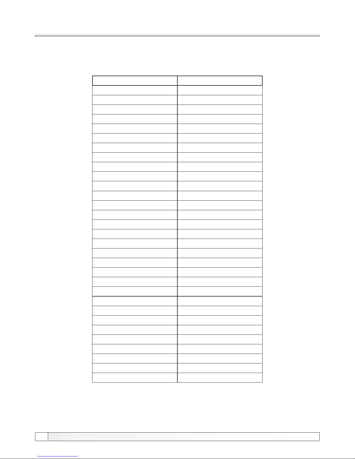
Table of resistance of the boiler sensor
TABLE OF RESISTANCE OF THE NTC 5k/25°C BOILER SENSOR
(measuring field from - 20 to + 130 °C)
Temperature (°C)
-20
-15
-10
-5
0
5
10
15
20
25
30
35
40
45
50
55
60
65
70
75
80
85
90
95
100
105
110
115
120
125
130
Resistance (Ω)
48.535
36.465
27.665
21.158
16.325
12.694
9.950
7.854
6.245
5.000
4.028
3.266
2.663
2.184
1.801
1.493
1.244
1.041
876
740,7
629,0
536,2
458,8
394,3
340,0
294,3
255,6
222,7
190,7
170,8
150,5
Page 15

2715
Technical manual El-Cm Compact
Errors
During the operation of the device some errors could appear.
If the display shows X (X stays for the number 0-5), it means that there is a regulator
operation error. The number shows its reason.
0 - too high temperature on the sensor > 90°C
1 - wrong value on the sensor the value is out of the measuring field (>99°C)
or the temperature sensor is wrong connected.
2 - sensor is not connected or the regulation measures the temperature which
is lower then -40°C in the boiler.
4 - the pressure detected an error, electric heaters switch off switch and
the pump still works for 30 sek.
5 - the cover of the regulation is opened dangerous contact with 400V
tension. Therefore the regulation switches off the heaters and the pump
(continuation of the normal functioning possible after setting the originary
operating mode. If this error repeatedly appears, the authorized person
should check the device.
If the systems falls into some kind of stand by (which practically occurs), when the installed power
is not enough to bring the system exactly on the desired temperature level, whereat the system is
not cooling down (for example the desired temperature is 70°C and at the temperature level of
67°C with activated power lower then maximal, the system reaches the stand by, which means
the temperature level remains invariable), after about 10 minutes the system shall increase the
power by itself.
ERRORS
Example: El-Cm Compact 12kW
Always after the start-up the electric boiler is warming up intensively, until the desired temperature
level has been reached.
When the desired temperature level has been reached, the regulator steers the operation of the
electric boiler allocating the power of activated heaters depending to the desired temperature to
be reached, step by step, i.e. 12 kW, 6 kW, 4 kW, 2 kW (MOD1). If by allocating of such power
levels the desired temperature can not be reached, the regulator recognizes that the power has to
be increased, therefore it reallocates the power as follows: 12 kW, 6 kW, 4 kW (MOD 2). If this is
not enough the regulator reallocates once again the power in following way: from 12 kW and 6 kW
(MOD 3). Leastways, the MOD 4 shall be activated, in which the electronic devices operate only at
12 kW level, and the modulation or the energy saving operation does not function. This could
mean that the whole system is oversized for the heater's capacity.
Page 16

HEATING TECHNIQUE
www.centrometal.hr
e-mail: [email protected]
Centrometal d.o.o. Glavna 12, 40306 Macinec, CROATIA
central tel: +385 40 372 600, fax: +385 40 372 611
service tel: +385 40 372 622, fax: +385 40 372 621
 Loading...