

Page 1
HEATING TECHNIQUE
Centrometal d.o.o. - Glavna 12, 40306 Macinec, Croatia, tel: +385 40 372 600, fax: +385 40 372 61 1
Tehnical instructions
Cm Pelet-set
REGULATION
120°C
80°C
30%
READY
1700
15k
0%
60°C
70°C
55°C
50°C
THE FIRST START-UP MUST BE D O N E BY AUTHORIZED PERSON
OTHERWISE PRODUCT WARRANTY IS N O T VALID
TURPS- 10/2017-v1_20-ENG
Cm Pelet-set
Page 2
Screen
SWITCHING ON
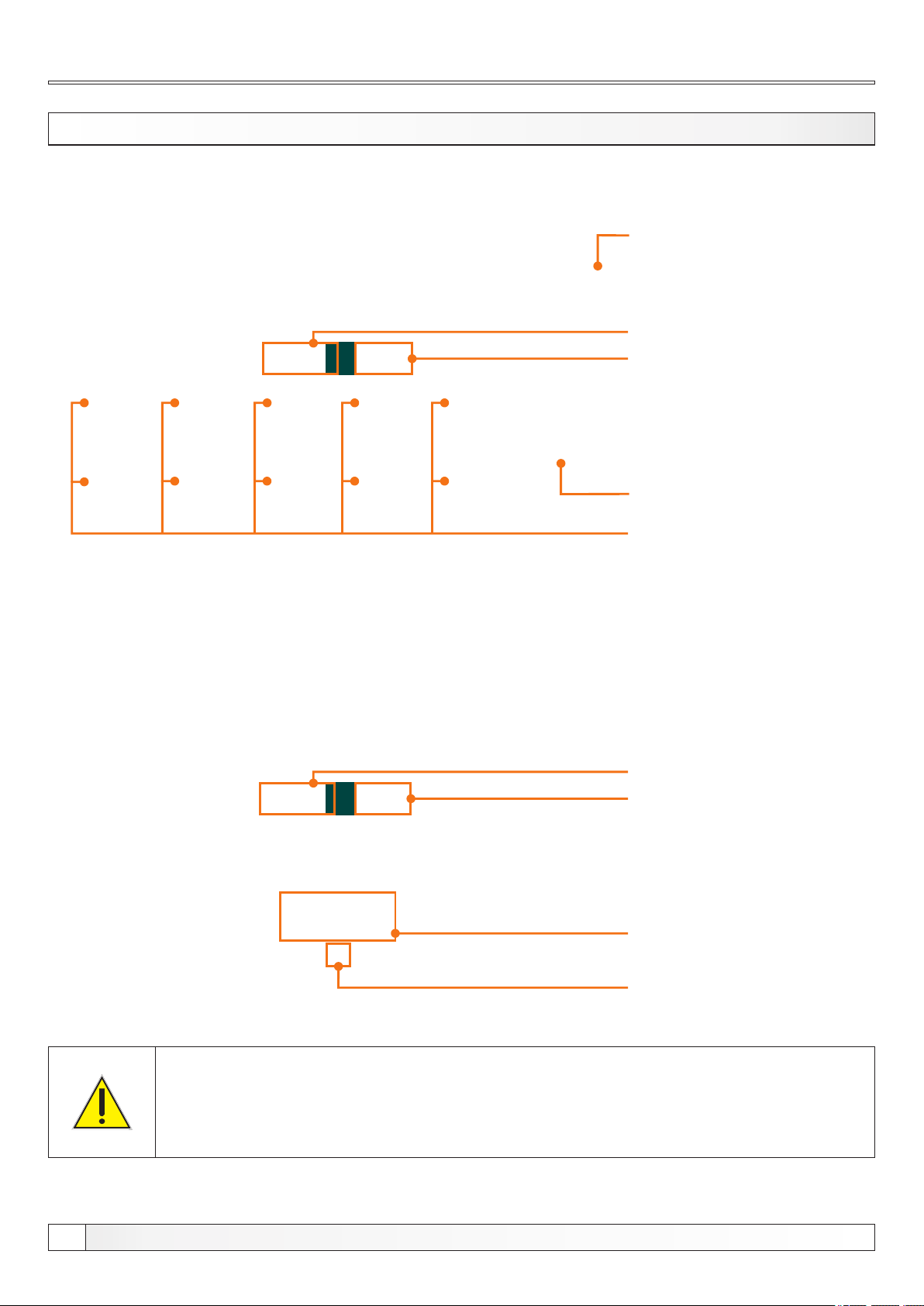
After turning on the main switch, screen will display language selection menu and software version.
You can choose between various languages. To select the language, press the flag of language you want.
Possibility of online burner
monitoring and burner control
(Additional equipment:
Cm WiFi-box)
Software version
Burner power
- 14 kW (Cm Pelet-set 14)
- 20-35 kW (Cm Pelet-set 35)
- 40/50 kW (Cm Pelet-set 50)
- 60-90 kW (Cm Pelet-set 90)
Page scroll
Language selection
If option "Language selection" is set to OFF under "DISPLAY" menu, initial message screen will be shown (picture
below). This screen will be shown as long it's set in the "Initial message time" option, under "DISPLAY" menu or until you
press "OK" button.
Software version
Burner power
- 14 kW (Cm Pelet-set 14)
- 20-35 kW (Cm Pelet-set 35)
- 40/50 kW (Cm Pelet-set 50)
- 60-90 kW (Cm Pelet-set 90)
’’OK’’ button
Initial message countdown
When turning on the main switch, touch screen must not be pressed. Otherwise
regulation will enter firmware update mode which is used only by authorized
technican. If this happens, please turn off main switch and turn it back on without
pressing the touch screen.
2
Technical instructions REGULATION Cm Pelet-set
Page 3
Main menu, Buttons
MAIN MENU
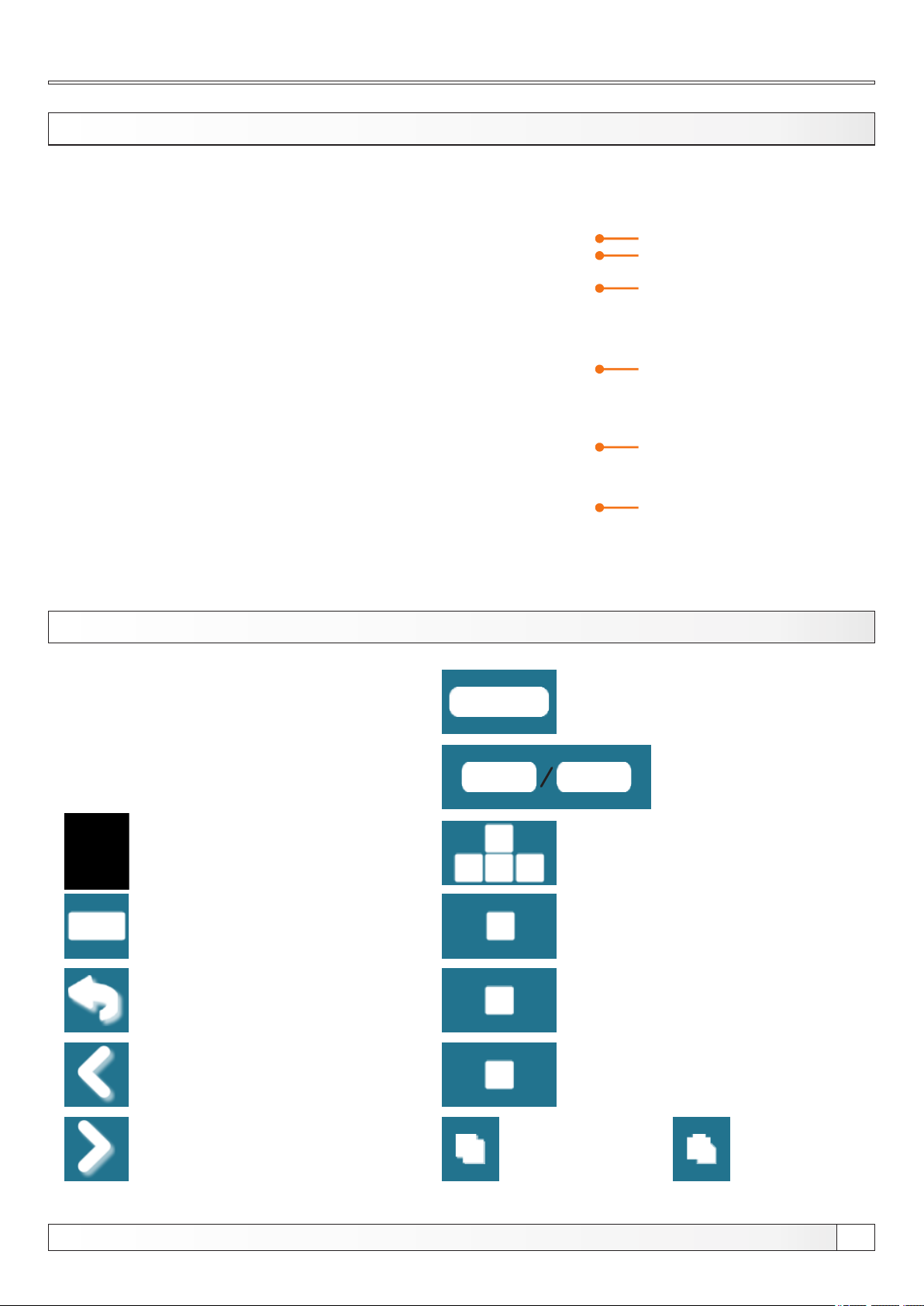
The main menu is used to select the desired submenu. To select a specific submenu you must press the appropriate icon
on the screen. To switch between the ’’Main menu’’ and ’’Boiler working display’’ press the button ’’View selection’’. To
switch between graphic view, numeric view or additional equipment of the boiler press ’’Boiler operation view’’ button.
Time
Date
View selection:
main menu / work
Boiler operation view:
graphic / numeric / additional
equipment
Current boiler status
Boiler start / stop
BUTTONS
Button ’’ON / OFF’’
options: on / off boiler operation’’
Button ’’VIEW SELECTION’’
options: main menu / work
Button ’’BOILER OPERATION DISPLAY’’
options:
graphic / numeric / additional equipment
Button ’’ENTER’’
Button ’’BACK’’
Button ’’PREVIOUS SCREEN’’
Button ’’OK’’
Button ’’START’’/’’STOP’’
Navigation buttons:
’’LEFT’’, ’’RIGHT’’, ’’UP’’, ’’DOWN’’
Button ’’DELETE’’
Button ’’FACTORY SETTINGS’’
Button ’’INFORMATION’’
Button ’’NEXT SCREEN’’
Technical instructions REGULATION Cm Pelet-set
Button ’’COPY’’ Button ’’PASTE’’
3
Page 4
Screen, Symbols
SIMBOLI
SYMBOLS
1 9
1 9
2
2
3
3
4
4
5
5
1110
1110
12
1312
13
6 7 8
6 7 8
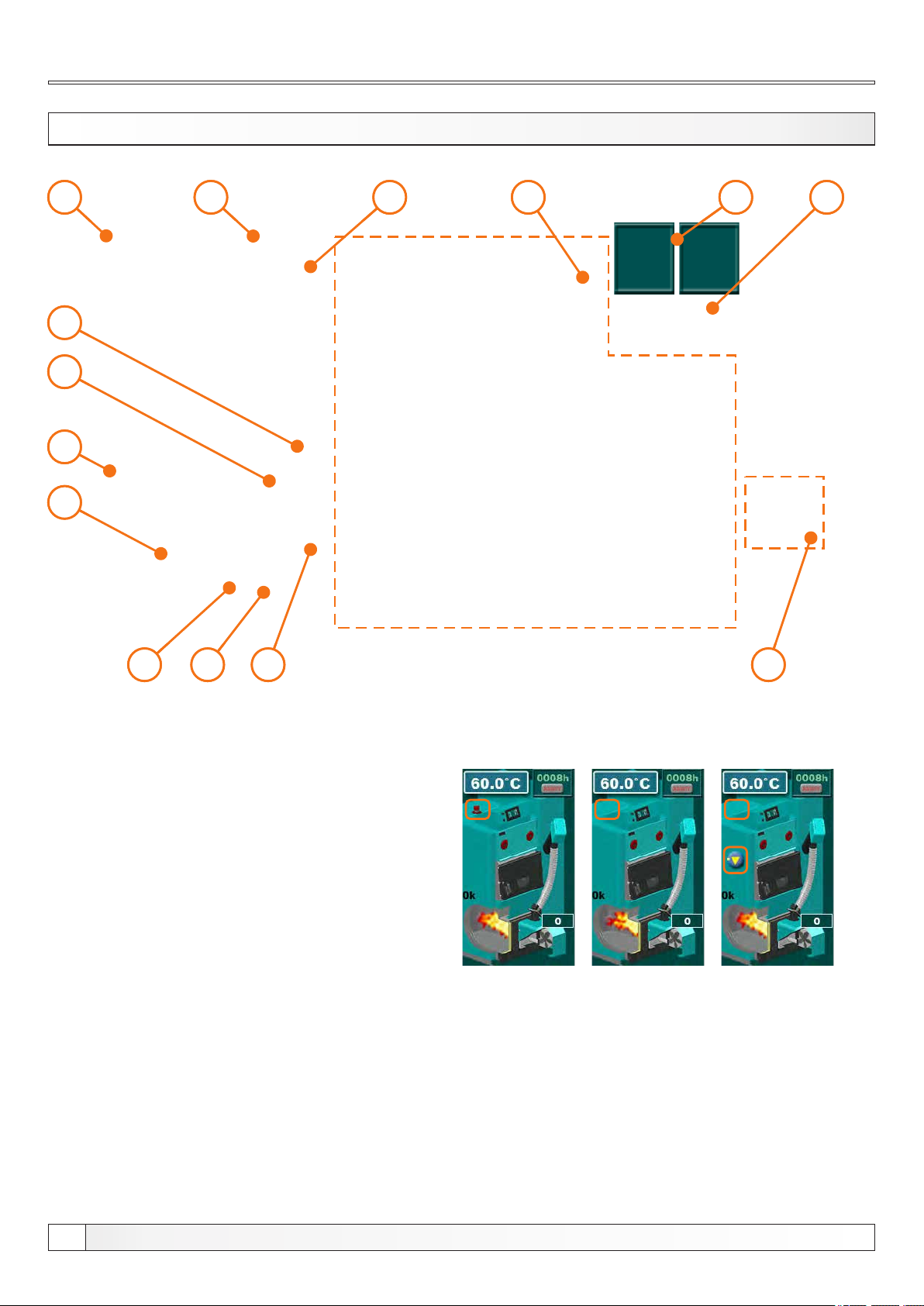
Symbols:
1 - Boiler temperature
2 - Fuel level *
3 - Transporter working
4 - Photocell
5 - Flame symbol
6 - Igniter working
7 - Burner fan working
8 - Burner fan rpm
9 - Burner working hours counter
10 - Burner working hours reset buttom
11 - Dynamic configuration view
(view is depending of set configuration)
12 - Work mode (winter/summer) / Additional
equipment view (cascade, wifi...)
13 - Outside temperature
14 - Boiler working stage
* - additional equipment
on screen only if additional equipment
is installed and enabled (fuel level sensor)
Boiler type display:
EKO-CK P EKO-CKB P
14
14
EKO-CKB P
+ built in boiler
recirculation
4
Technical instructions REGULATION Cm Pelet-set
Page 5
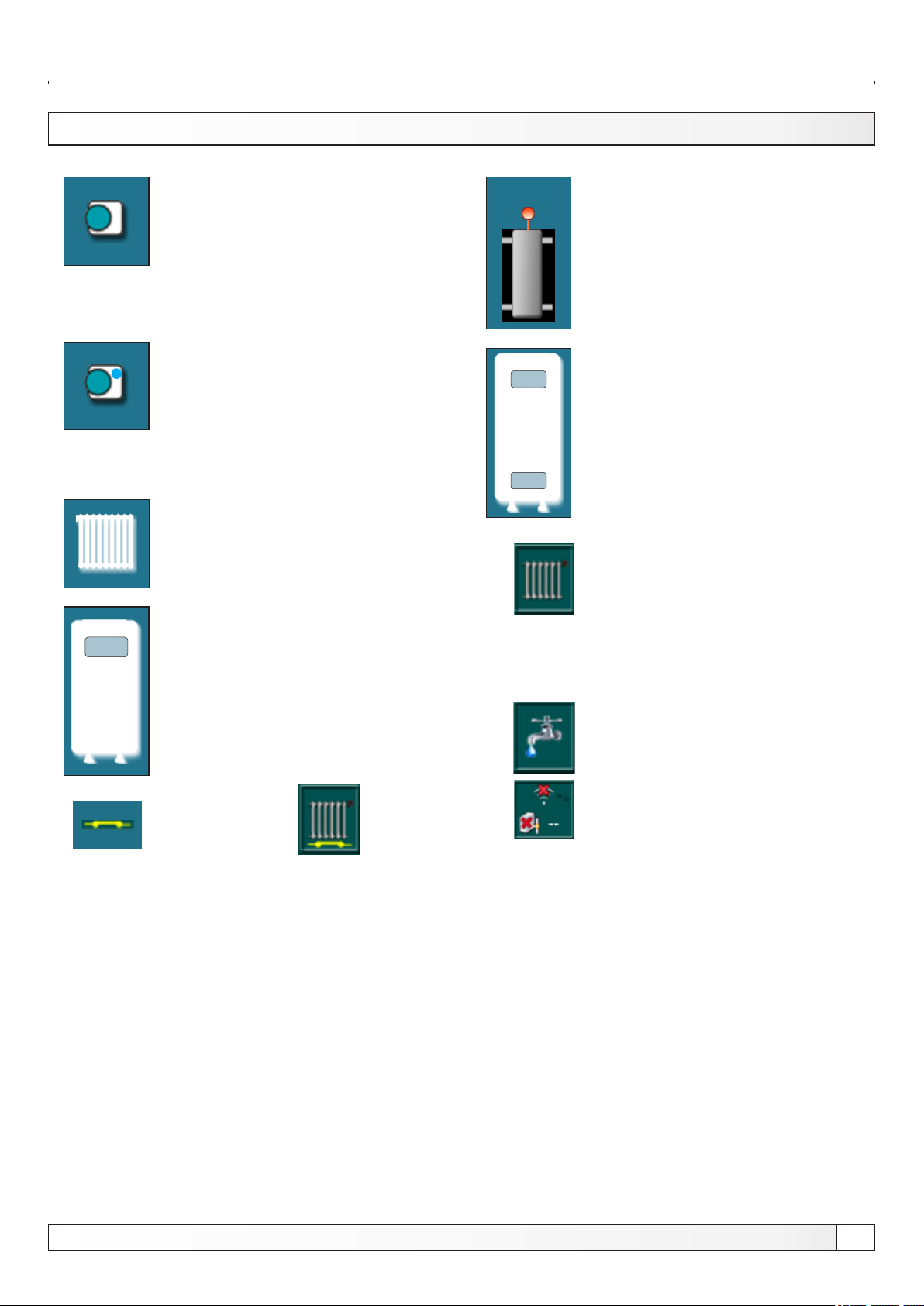
SYMBO LS
Room thermostat
Next to the room thermostat
symbol bright blue circle (the
room thermostat has requested
for operating the pump, the pump
does not work if you have not met
all the conditions for its operation,
for example. low temp. in the
boiler, otherwise normally works)
Screen, Symbols
60°C
Hydraulic crossover with the
current temperature
(there are configuration without
temp. sensor)
70°C
Accumulation tank with current
temperature at top of the tank and
at the bottom of the tank.
50°C
55°C
Heating circuit
Domestic hot water tank
with current temperature
External control ( / )
View/additional equipment button
(All items of additional equipment
are enabled)
Winter working mode
(only heating)
Winter working mode
(heating + DHW)
Summer working mode
(only DHW)
Cm WiFi-box - not connected
Cm WiFi-box - connected
Cascade
Some items of the additional
equipment are disabled
All items of additional equipment
are disabled
Technical instructions REGULATION Cm Pelet-set
5
Page 6

Symbols, Adjusting the paramteres
SYMBOLS - RETURN FLOW PROTECTION
3-way thermostatic mixing valve
+ pump
3-way mixing valve with actuator and
return flow temp. sensor
+ pump
ADJUSTING THE PARAMETERS
A B
C D
4-way manual mixing valve
+ pump
4-way mixing valve with actuator and
return flow temp. sensor
+ pump
There are 4 different menu types for adjusting the parameters:
A - this menu is used to set the parameters that have numerical values (°C, RPM, time...)
example: adjust the burner fan rpm, adjusting the boiler temp. etc...
B - this menu is used to set parameters that must be selected (marked) to be enabled and there can be multiple selected
(enabled) items
NOTE: some enabled options disable another one (they can't be enabled at the same time)
example: enable additional equipment: flap, air cleaning, CM2K, Cm-WiFi-box...
C - this menu is used to set the parameters that must be selected but there can be only one selected item
example: set the type of the DHW sensor
D - this menu is used to set the parameters where are many items to be adjusted
example: adjust the burner working parameters on power P2
6
Technical instructions REGULATION Cm Pelet-set
Page 7
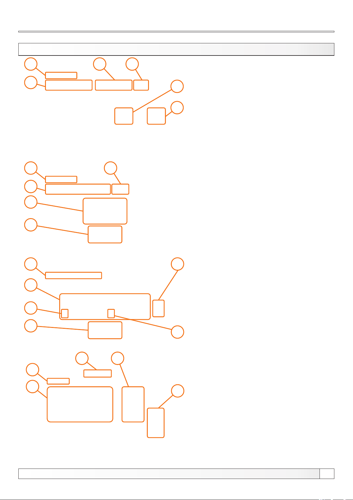
ADJUSTING PARAMETERS METHODS (examples)
Adjusting the parameters
2
2
3
4
1
1
3
5
4
1 -parameter you are adjusting
2 - value adjustment box
3 - set value
5
4 - value type
5 - info button (displays factory, min. and max. values)
6 - resets the current value to the factory value
6
1 - parameter you are adjusting
2 - value adjustment box
3 - selected option (only one option can be selected)
4 - confirm button
5 - factory value
2
5
4
1
2
3
1
4
3
1 - parameter you are adjusting
2 - items that can be enabled
3 - next page button
4 - confirm button
5 - selected (enabled) item
6 - deselected (disabled) item
6
1 - parameter you are adjusting
2 - switch between sheets (only for parameters which
have multiple sheets)
3 - parameter description
4 - parameter current value (press 2 times to enter
5
adjusting mode)
5 - up/down scroll buttons
NOTE: after parameter changing press the "CONFIRM" button to store new value. If you don't want to save the set
value, press "BACK" button.
Tehničke upute REGULACIJA Cm Pelet-set
Technical instructions REGULATION Cm Pelet-set
7
Page 8
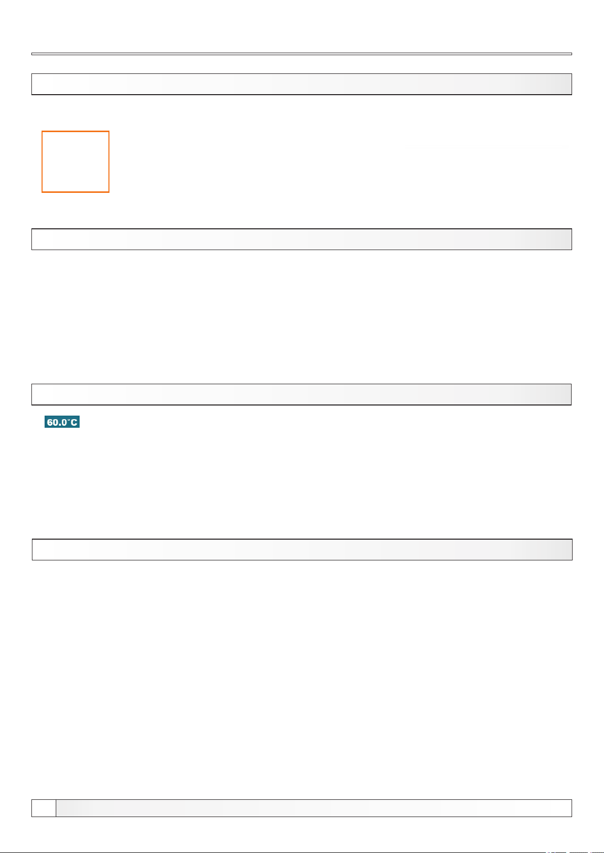
Maintenance, Cleaning
1.0. MAINTENANCE
1.1. CLEANING THE BURNER
Under "CLEANING" menu are two options:
Cleaning: this option is used to start the burner fan on the set RPMs to
clean the burner grate (note: depending of the pellets quality grate will
be more or less clean. After this procedure, burner grate should be
removed and cleaned and the burner head should also be cleaned.)
1.1.1. CLEANING
1.1.2. BURNER FAN
Burner fan: this option sets the burner fan RPMs during cleaning
Press the "START" button to start the burner fan for 10 min.
After pressing the "START" button countdown is started for 10 min,
after which burner fan stops automaticaly
Press "AIR VALVE" button to open the electro-magnetic valve and to
clean the burner with compressed air.
After pressing the "AIR VALVE" countdown ist started for 60 sec in
which time "AIR VALVE" button is disabled to alow compressor to fill its
tank.
This option is used to adjust burner fan RPMs during cleaning
procedure
Possible adjustment:
- Factory adjustment: 3000 rpm
- Minimal adjustment value: 500 rpm
- Maximal adjustment value: 3000 rpm
NOTE: burner cleaning option is not replacing the need for manual
cleaning of the burner and burner grate. It should be manually cleaned
regulary according to the technical manual.
8
Technical instructions REGULATION Cm Pelet-set
Tehničke upute REGULACIJA Cm Pelet-set
Page 9
Temperature , Schedule
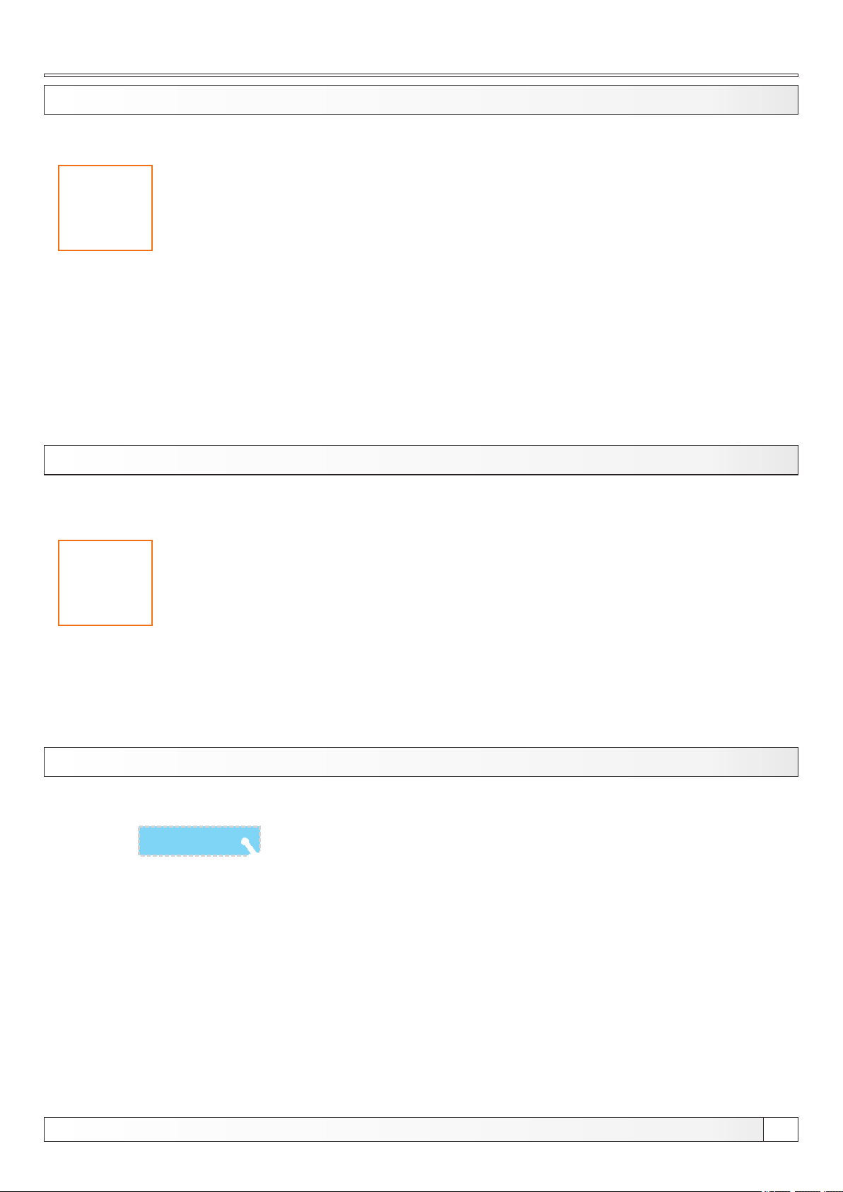
2.0. TEMPE RATURE
Temperature menu shows only items applicable to the set configuration. In next section of the manual all avalible
configurations and schemes are listed.
Availible temperature settings will be described at every individual configuration and scheme in
"CONFIGURATIONS" section of this manual.
NOTE: this is only representation picture, actual possible adjustment depends on set configuration.
3.0. SCHED ULE / 3.1. BOI LER
This option is used to set the burner working time according to the set time. You can set 3 tables with different settings
and only 1 table can be active. You can set ON/OFF 3 times during 1 day and every day can be individualy set.
NOTE: in the same way you can set other schedules: BOILER, DHW, RECIRCULATION
3.1.1. SCHEDULE
This option is used to select active "SCHEDULE TABLE" that you have set
Possible adjustment:
- Factory adjustment: OFF
- Table 1
- Table 2
- Table 3
Technical instructions REGULATION Cm Pelet-set
9
Page 10
Table, History
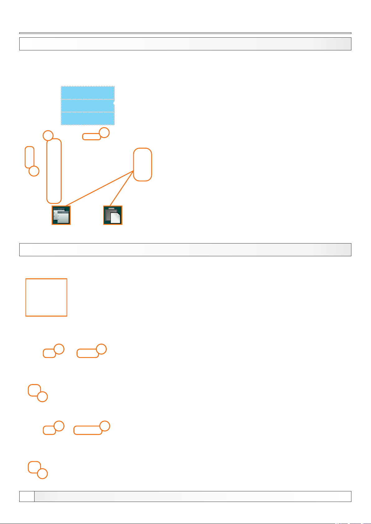
3.1.2. TABLE 1/2/3
This option is used to set "SCHEDULE TABLES". Every table can be
individualy set.
2
3
COPY
BUTTON
4. HISTORY
1
PASTE
BUTTON
1 - current table you are adjusting (table 1 / table 2 / table 3)
2 - day of the week
3 - green - burner start (on)
red - burner stop (off)
Press the box to adjust the time
You can adjust 3 start and stop during 1 day
You can copy/paste from one day to another by pressing the "day box"
of the day which you want to copy, press the "COPY" button and press
the desired "day box" and press "PASTE" button.
This option is used to see the
history of the occured "ERRORS"
and "WARNINGS"
10
1 2
3
1 2
3
This option is used to see the history of the occured "ERRORS"
1 - error code
2 - error description
3 - time and working stage (OFF) when error occured
Error codes are marked with letter "E"
List of all error codes are listed in the "Cm Pelet-set manual"
This option is used to see the history of the occured "WARNINGS"
1 - warning code
2 - warning description
3 - time and working stage (OFF) when warning occured
Warning codes are marked with letter "W"
List of all warning codes are listed in the "Cm Pelet-set manual"
Technical instructions REGULATION Cm Pelet-set
Page 11
Operation, Forced shutdown, Manual test
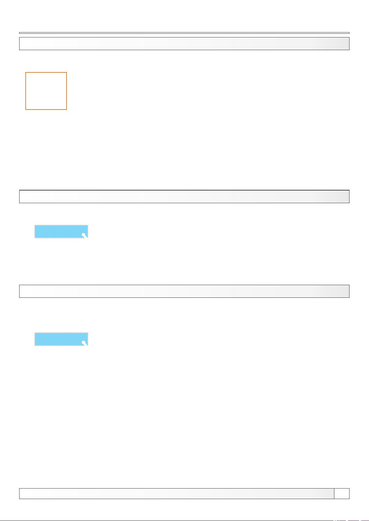
5. OPERATION
This menu is used to set various parameters, enable/disable various additional equipment and functions, various work
modes, manual test etc.... This menu is designed for end user.
NOTE:
some of the options in this menu are GREYED OUT (disabled) and they can't be changed.
They are only shown to see settings/values of some options.
View in this menu depend of selected options and additional equipment.
5.1. FORCED SHUTDOWN
This option is used to forced shut down of the burner in any working
stage. Before pressing the "FORCED SHUTDOWN" you must switch
off the burner on the ’’ON/OFF’’ switch and confimt ’’STOP’’ action on
the main display.
NOTE: after "FORCED SHUTDOWN" you must open the boiler
door with burner, and clean the burner grate before starting the
burner again.
5.2. MANUAL TEST
This option is used to check relay outputs, connection to the electric devices and the working of the electric devices.
Items:
- Burner fan - you can check working of the burner fan on 2 speeds (max rpm and 1700 rpm) - when you start the test,
measured rpms are displayed on screen
- Feeder screw - you can check working of the feeding transporter
- Heater + burner fan - you can check working of the burner heater (igniter) - to protect the heater from burning out,
burner fan is started automatically when you start the heater
- Pump P1/DHW/RECIRCULATION - you can check working of the connected pumps
- 1. Circuit / 2. Circuit - you can check working of the devices of the mixing heating circuits (pumps, motor valves open
close)
- Additional equipment - submenu for manual test of the installed additional equipment
NOTE: Items displayed in this menu and in "Additional equipment" submenu depends of set configuration and
installed additional equipment.
Technical instructions REGULATION Cm Pelet-set
11
Page 12
Filling conveyors, Save/load
5.3. FILLING CONVEYORS
NOTE:
if the transporter gets empty, you must fill it
before starting the burner.
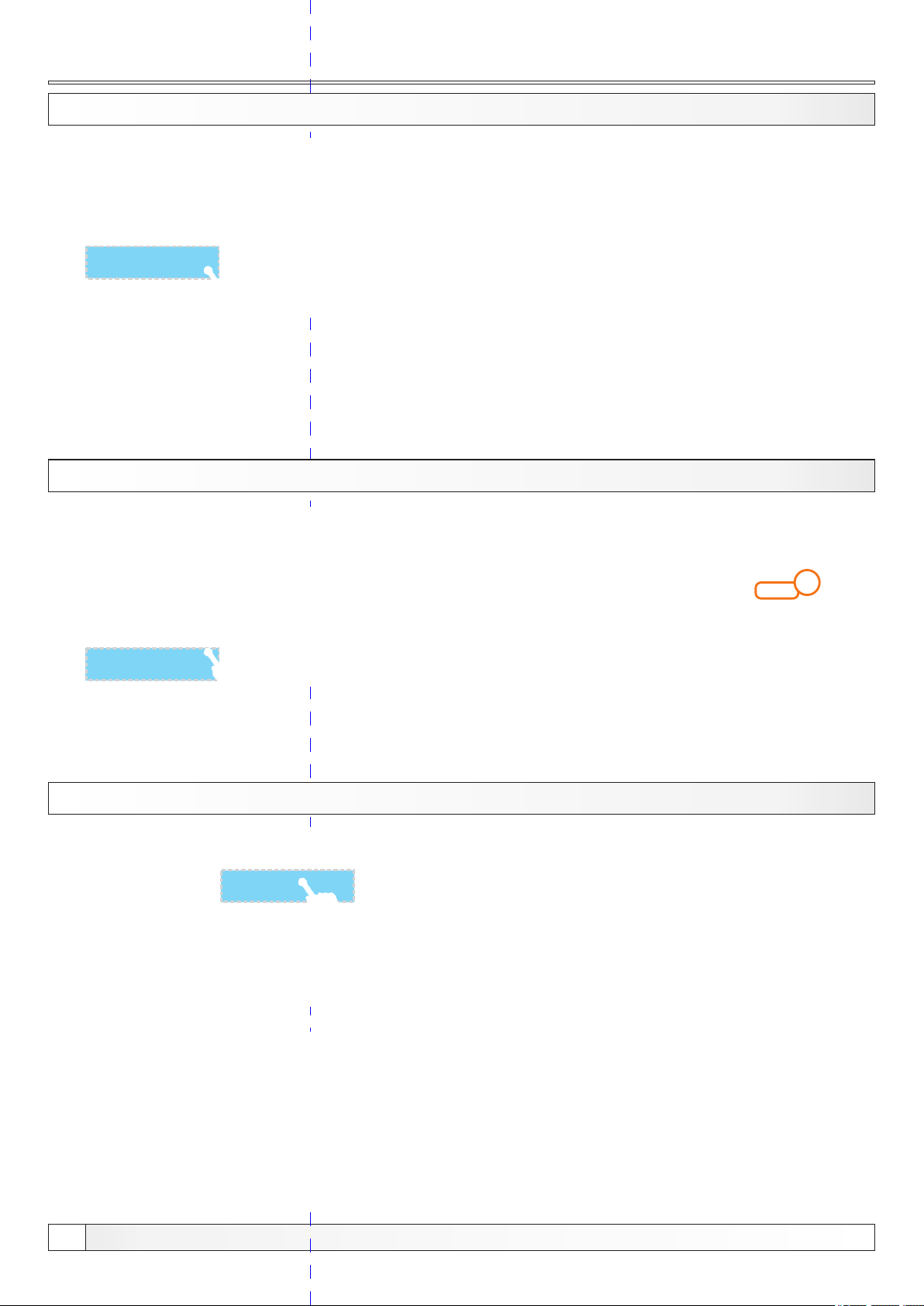
5.4. VEIGHING CHECK
Filing conveyors:
This option is used for the initial filling of the transporter. Also it can be
used if the transporter becomes empty. Recommended is to start the
filling process and wait until it finishes to be sure that transporter is full
(20 min.).
Before starting this option, disconnect the PVC tube from the burner
and put a bucket/bag under it. After process is finished put the pellet
from the bucket/bag back to the tank and connect PVC tube back to
the burner.
Check filling at start:
This otion is used to check filling at start. Pressing the ’’START’’ button
transporter starts to work and works continuously for set time (counter
is started). This time can be adjusted under option Filling at start under
’’INSTALLATION’’ menu. After this process is finished, open the door
with burner and check if the pellets have cover the el. heater. If not,
filling at start must be adjusted and checked again.
1
This option is used to check pellet delivery amount.
You can set the transporter working time (1) after which you want to weight the pellet.
On screen is displayed factory amount and last measuring which can be done only by authorized serviceman (if has
been done, if not factory and last weighning is the same).
5.5. SAVE/LOAD
This option is used to save parameters, load / load service parameters
and delete saved parameters.
SAVE - save current settings
LOAD - load saved setting
LOAD SERVICE - load setting autorized serviceman saved
DELETE - delete saved settings
You can save multiple setting under different names and you can load
and delete saved setting.
12
Technical instructions REGULATION Cm Pelet-set
Page 13

Standard equipment, Sensors, Photocell, Circuits
5.6. STANDARD EQUIPMENT
This option is used for adjusting standard equipment of Cm Pelet-set
Options:
- Sensors - you can set the sensor type (PT1000 - factory or NTC 5K)
- Photocell - you can adjust photocell parameters
- 1.Circuit / 2. Circuit - you can adjust mixing heating circuits parameters
- DHW - you can adjust DHW parameters
5.6.1. SENSORS
This option is used for adjusting the sensors type (NTC 5K or PT1000)
Factory: PT1000
Option: PT1000 / NTC 5K
5.6.2. PHOTOCELL
This option is used for adjusting photocell parameters
5.6.3/5.6.4. 1. CIRCUIT / 2. CIRCUIT
This option is used for adjusting the mixing heating circuits.
NOTE:
some parameters are shown in"OPERATION" menu but can't be
changed. They can be changed only in "INSTALLATION" menu
which is under PIN (only for authorized serviceman).
Technical instructions REGULATION Cm Pelet-set
13
Page 14
Circuits
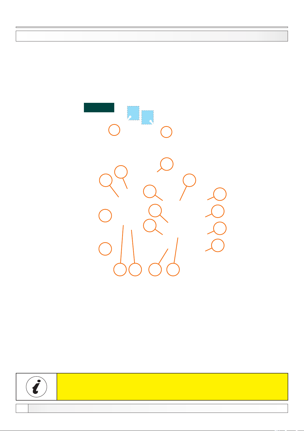
5.6.3.1 - 5.6.4.2 1. CIRCUIT / 2. CIRCUIT
It's possible to view all enabled mixing heating circuits (set temperatures, measured temperatures, heating type,
working of the pumps etc...). To enter this view press / button and then .
If there are more than 2 mixing heating circuits enabled you can switch view betwen them with buttons.
3a
1a
1
2.
2a
2
3
5a
5
4a
4
1.
9
6a
8a
7a
8
7
6
For each heating circuit can be specifically select items.
For example, you can Include / exclude heating circuits, turn on/off room corrector, choose heating type in each circuit
(radiators / floor), choose the mode (day / night).
1 - Mixing valve (1.circuit)
2 - The calculated flow temperature (1.circuit)
3 - Current measured flow temperature (1.circuit)
4 - Heating type on 1. circuit (radiators or floor heating)
5 - Room corrector „CSK“ on 1. circuit (if turned off,
icon disappears)
Items 1a - 8a have the same meaning as items 1-8 (described above) which
only relate to 2. heating circuit or some other circuit depend how many circuits
is selected.
14
6 - The desired temperature + deviation by room corrector
(1.circuit)
7 - Current measured room temperature (shown only
if the room corrector is turned on) in 1.circuit
8 - Mode (1.circuit) (day / night)
9 - Outer temperature (outer sensor)
Technical instructions REGULATION Cm Pelet-set
Page 15

Circuits settings
SETTING PARAMETERS FOR EACH HEATING CIRCUIT
Regulation can control up to two mixing heating circuits. They must be enabled and set under "INSTALLATION" menu.
To make adjustment of each circuits go to the "OPERATION" menu then "STANDARD EQUIPMENT" menu.
Possible selection:
Factory: ON
Option: ON, OFF
By using this option you can enable/disable heating circuits.
Possible selection:
Factory: 1.0
Option: 0.1 - 4.0
By using this option you can set heating curve value.
Possible selection:
Factory: 1.0
Option: 0,1 - 5,0
By using this option you can set correction value.
Technical instructions REGULATION Cm Pelet-set
15
Page 16

Circuits settings
Possible selection:
Factory: 20,0°C
Option: 5.0°C - 30.0°C
By using this option you can set day room temperature.
Possible selection:
Factory: 20,0°C
Option: 5.0°C - 30.0°C
By using this option you can set night room temperature.
Possible selection:
Factory: DAY TEMP.
Option: Day temp. / Night temp. / Table
By using this option you can set working mode of the heating circuit
By using this option you can set table for working mode of the heating circuit.
NOTE: you can change settings of any heating circuit in the same way.
16
Technical instructions REGULATION Cm Pelet-set
Page 17

Additional equipment, Freeze guard, Work mode
5.7. ADDITIONAL EQUIPMENT
This option is used to set additional equipment that isn't part of
standard delivery.
Options:
- Air cleaning - turn on/off burner air cleaning
- Flap - turn on/off burner flap
- External control - turn on/off external control (start)
- Cascade - turn on/off the cascade and set some of its options
- CM-GSM - turn on/off CM-GSM module
- Internet supervision - turn on/off internet control and adjust some of
its options
- CMSR100 - turn on/off fuel level sensor and adjust some of its
options
- Suction system - turn on/off suction system and adjust some of its
options
NOTE:
additional equipment must be enabled under "INSTALLATION"
menu (PIN required) and only then is shown in this menu.
Some of the items shown here can be adjusted only under
"INSTALLATION" menu and can be changed only by authorized
serviceman.
5.8. FREEZE GUARD
This option enables to set on/off freeze guard
Possible adjustment:
Freeze guard:
- Factory adjusted: OFF
- Options: ON / OFF
Type of protection:
- Factory: "Heating + Pumps"
- Options: "Heating+Pumps" / "Pumps only"
Option:
- Factory: "To._min/Taf_min"
- Options: "To._min/Taf_min" / "Toutside"
5.9. WORK MODE
This option enables to set working mode
Possible adjustment:
- Factory adjusted: WINTER
- Options: WINTER (heating + DHW) / SUMMER (only DHW) /
AUTO (DHW <> heating + DHW)
Technical instructions REGULATION Cm Pelet-set
17
Page 18

Time to burner extinguishing, Modulation, Display
5.10. TIME TO BURNER EXTINGUISHING
This option is used to set time for burner shut down. In case of
continuous burner working for this time, burner will shut down (in this
process it will clean the grate, with burner fan or air cleaning if it’s
installed). After burner shutdown process, burner will start again and
this counter will be reset. Also at every shut down, this counter is reset.
Posible adjustment:
- Factory adjustment: 0 min (OFF)
- Options: 0 - 360 min
5.11. MODULATION
This option is used to enable/disable burner modulation and to show
set parameters of modulation.
Posible adjustment:
- Factory adjustment: OFF
- Options: ON / OFF
Atfer enabling the ’’MODULATION’’ option you can see set
parameters of the modulation.
6. DISPLAY
Modulation beginning - set how many °C below set boiler temp.
modulation will start (options: -4°C, -3°C, -2°C, -1°C)
Modulation percentage - set in how many steps (percentages of
power) modulation will work (options depends of the set burner power)
Burner power:
power 90, 35 kW have 4 steps of modulation (80/65/50/30%)
power 70, 50, 30, 25 kW have 3 steps of modulation (80/60/50%)
power 60, 40, 20, 14 kW have 2 steps of modulation (75/50%)
NOT E: mod ulati on para mete rs can b e s et onl y u nder
’’INSTALLATION’’ menu which is under PIN.
This option is used to set display/sound parameters
Options:
- Screensaver - you can set the screensaver time
- Language selection - you can turn on/off language selection menu after turning on main switch
- Initial message time - you can set time of the initial message if you turn off language selection menu (after this time
runs out, main screen will be shown)
- Show timers - show timers on the lower part of the screen
- Date & time - you can set the date and time
- Sound volume - you can set the touch sound type
- Sound type - you can set the touch sound volume
18
Technical instructions REGULATION Cm Pelet-set
Page 19
Info, Correction, Chimney sweeper
7. INFO
This option is used to see various informations regarding regulation and burner
Options:
- Statistics - you can see working times of various parts (burner working, working in summer mode, freeze guard,
burner starts, burner fan working, heater working, heater starutups, screew working, pumps working...)
- Software version - you can see burner power (14 kW, 20-35 kW, 40/50 kW or 90 kW), regulation software version and
WiFI ID number (if Cm WiFi-box is installed)
- Selected configuration - you can see set configuration
- Current file - you can see which saved file is currently in use
- Selected burner power - you can see set burner power
9. CORRECTION
1
This option is used make correction of pellet delivery. You can decrease delivery by 3 steps. Steps are factory
configurated (or configured by authorized serviceman in "INSTALLATION" menu, under PIN) for every working stage
(power). Icon changes according the set step. "0" is no change and factory set.
2 3
10. CHIMNEY SWEEPER
10
10
This option is used to enable and set "CHIMNEY SWEEPER MODE"
Options:
- Chimney sweeper - you can enable/disable "CS" mode
- Power - you can set burner power for "CS" mode
- Minimum boiler temerature - you can set the minimum boiler temperature for "CS" mode
"CS MODE" - this mode enables you make flue gas measurement on selected burner power and set minimum boiler
temperature. In this mode boiler will be exluded from cascade, external control etc. and work only according boiler
temperature. Also in this mode modulation temperatures are lower so burner will modulate later, to enable longer
measurement on set power.
Technical instructions REGULATION Cm Pelet-set
19
Page 20

11. INSTALLATION
11
This menu is used only by authorized servicemen
For entry in "INSTALLATION" menu is necessary to input PIN.
Burner working stage
Installation
BURNER WORKIN STAGE:
OFF -
S7-3 -
PFON230 -
burner doesn’t work (OFF - burner will not start)
burner start - only burner fan is working
A0 -
start of start up safety time measuring, start of igniter working
A1 -
start of transporter working (initial filling)
A2 -
end of initial filling (transporter stops), waiting for the flame (in case flame doesn’t appear in set time
A3 -
error E2 will appear, ignition fail)
start of time measuring to enter into stabilization stages and additional igniter working
A4 -
end of additional igniter working, start of time measuring to enter transition stage PP1
A5 -
transition stage 1
PP1 -
transition stage 2
PP2 -
transition stage 3
PP3 -
transition stage 4
PP4 -
transition stage 5
PP5 -
working stage before enter nominal power (increased rpms of the burner fan regarding set power)
A6 -
burner nominal power (P6, P5, P4, P3, P2 - depends of the burner set power)
PX -
modulation stage 4
M4 -
modulation stage 3
M3 -
modulation stage 2
M2 -
modulation stage 1
M1 -
waiting stage (STANDBY - burner waits any of the start condition
power failure and power return stage - (burner tries to establish normal work after power supply failure
and return of the power supply)
stage of full intake tube filling sensor (burner tries to establish normal work correction of the transporter
F1 -
working) - only CPPL-90
20
Technical instructions REGULATION Cm Pelet-set
Page 21
Configurations
13. CONFIGURATIONS
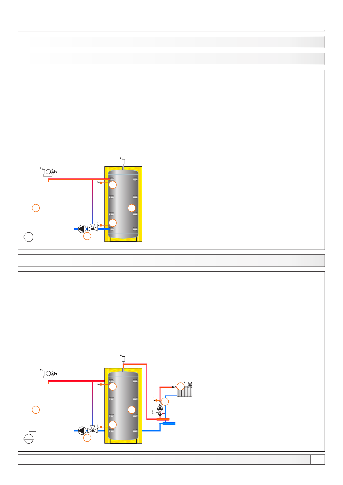
13.1. CONFIGURATION A-0-0
bar
4
1
5
EKO-CK P
1 - Boiler EKO-CK P + Cm Pelet-set
2 - Accumulation tank
3 - 3-way themostatic mixing valve + pump (P1)
(return flow protection)
4 - Accumulation tank upper temp. sensor (BUFFER1)
5 - Accumulation tank lower temp. sensor (BUFFER2)
Temperatures:
Boiler temp.: 80°C (80-90°C)
Tpuf: 80°C (65-80°C)
dTpuf: 10°C (5-30°C)
dTbuf-off: 5°C (3-50°C)
2
3
13.2. CONFIGURATION A-0-1
bar
4
1
EKO-CK P
1 - Boiler EKO-CK P + Cm Pelet-set
2 - Accumulation tank
3 - 3-way themostatic mixing valve + pump (P1)
(return flow protection)
4 - Accumulation tank upper temp. sensor (BUFFER1)
5 - Accumulation tank lower temp. sensor (BUFFER2)
6 - Mixing heating circuit
7 - 1. circuit flow sensor (CIRCUIT1) + pump (P4) + actuator (MVAL1)
Temperatures:
Boiler temp.: 80°C (80-90°C)
Tpuf: 80°C (65-80°C)
dTpuf: 10°C (5-30°C)
dTbuf-off: 5°C (3-50°C)
Tbuf min.: 20°C (5-85°C)
6
7
2
M
5
3
Technical instructions REGULATION Cm Pelet-set
21
Page 22
Configurations
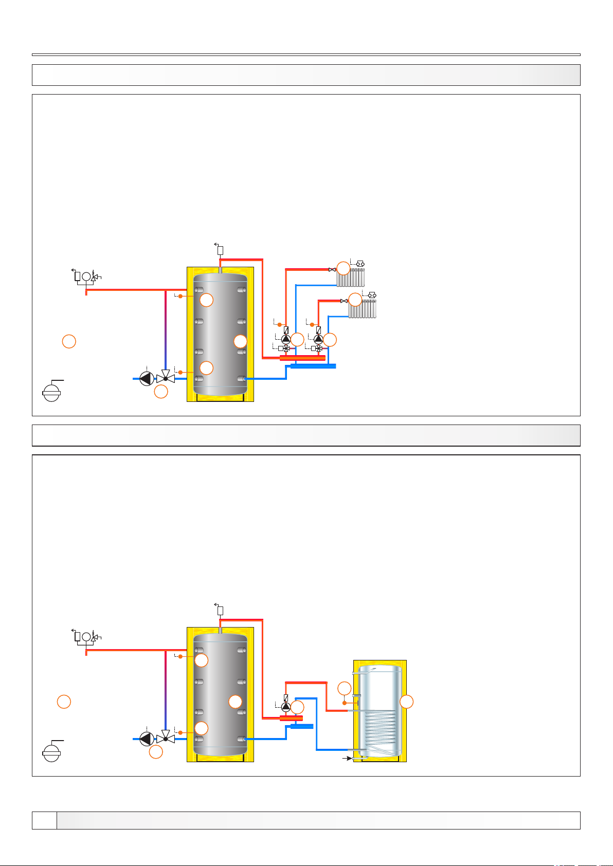
13.3. CONFIGURATION A-0-2
bar
4
1
5
EKO-CK P
1 - Boiler EKO-CK P + Cm Pelet-set
2 - Accumulation tank
3 - 3-way themostatic mixing valve + pump (P1)
(return flow protection)
4 - Accumulation tank upper temp. sensor (BUFFER1)
5 - Accumulation tank lower temp. sensor (BUFFER2)
6 - Mixing heating circuit (2x)
7 - 1. circuit flow sensor (CIRCUIT1) + pump (P4) + actuator (MVAL1)
8 - 2. circuit flow sensor (CIRCUIT2) + pump (P5) + actuator (MVAL2)
Temperatures:
Boiler temp.: 80°C (80-90°C)
Tpuf: 80°C (65-80°C)
dTpuf: 10°C (5-30°C)
dTbuf-off: 5°C (3-50°C)
Tbuf min.: 20°C (5-85°C)
6
6
2
8
7
MM
3
13.4. CONFIGURATION A-1-0
bar
4
1
1 - Boiler EKO-CK P + Cm Pelet-set
2 - Accumulation tank
3 - 3-way themostatic mixing valve + pump (P1)
(return flow protection)
4 - Accumulation tank upper temp. sensor (BUFFER1)
5 - Accumulation tank lower temp. sensor (BUFFER2)
6 - DHW tank
7 - DHW tank pump (P2)
8 - DHW tank sensor (DHW)
Temperatures:
Boiler temp.: 80°C (80-90°C)
Tpuf: 80°C (65-80°C)
dTpuf: 10°C (5-30°C)
dTbuf-off: 5°C (3-50°C)
Tdhw: 50°C (10-70°C)
dTdhw: 5°C (3-20°C)
8
2 2
7
EKO-CK P
22
5
3
Technical instructions REGULATION Cm Pelet-set
Page 23
Configurations
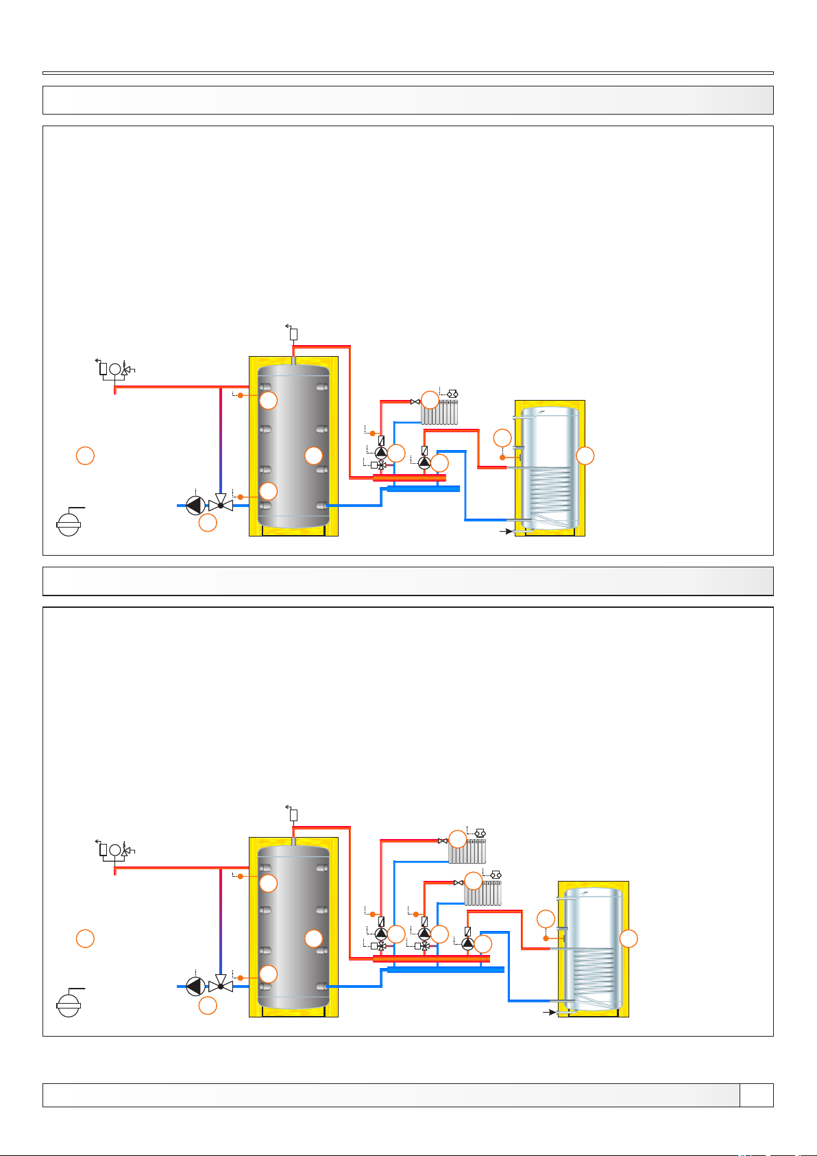
13.5. CONFIGURATION A-1-1
bar
4
1
5
EKO-CK P
1 - Boiler EKO-CK P + Cm Pelet-set
2 - Accumulation tank
3 - 3-way themostatic mixing valve + pump (P1)
(return flow protection)
4 - Accumulation tank upper temp. sensor (BUFFER1)
5 - Accumulation tank lower temp. sensor (BUFFER2)
6 - Mixing heating circuit
7 - DHW tank
8 - 1. circuit flow sensor (CIRCUIT1) + pump (P4) + actuator (MVAL1)
9 - DHW tank pump (P2)
10 - DHW tank sensor (DHW)
Temperatures:
Boiler temp.: 80°C (80-90°C)
Tpuf: 80°C (65-80°C)
dTpuf: 10°C (5-30°C)
dTbuf-off: 5°C (3-50°C)
Tdhw: 50°(10-70°C)
dTdhw: 5°C (3-20°C)
Tbuf min.: 20°C (5-85°C)
6
10
2
8
M
9
7
3
13.6. CONFIGURATION A-1-2
bar
4
1
EKO-CK P
1 - Boiler EKO-CK P + Cm Pelet-set
2 - Accumulation tank
3 - 3-way themostatic mixing valve + pump (P1)
(return flow protection)
4 - Accumulation tank upper temp. sensor (BUFFER1)
5 - Accumulation tank lower temp. sensor (BUFFER2)
6 - Mixing heating circuit (2x)
7 - DHW tank
8 - 1. circuit flow sensor (CIRCUIT1) + pump (P4) + actuator (MVAL1)
9 - 2. circuit flow sensor (CIRCUIT2) + pump (P5) + actuator (MVAL2)
10 - DHW tank pump (P2)
11 - DHW tank sensor (DHW)
Temperatures:
Boiler temp.: 80°C (80-90°C)
Tpuf: 80°C (65-80°C)
dTpuf: 10°C (5-30°C)
dTbuf-off: 5°C (3-50°C)
Tdhw: 50°(10-70°C)
dTdhw: 5°C (3-20°C)
Tbuf min.: 20°C (5-85°C)
6
6
11
2
8 9
MM
10
7
5
3
Technical instructions REGULATION Cm Pelet-set
23
Page 24
Configurations
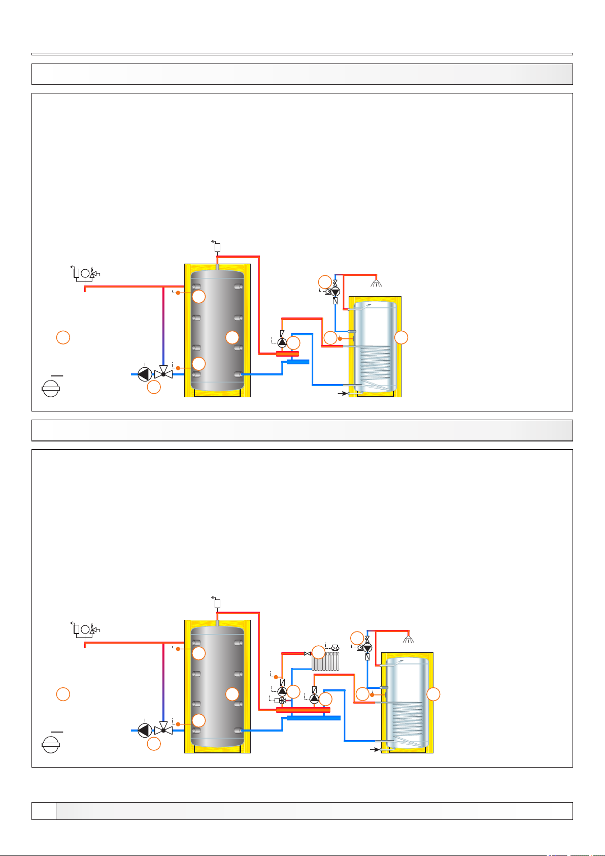
13.7. CONFIGURATION A-2-0
bar
4
1
5
1 - Boiler EKO-CK P + Cm Pelet-set
2 - Accumulation tank
3 - 3-way themostatic mixing valve + pump (P1)
(return flow protection)
4 - Accumulation tank upper temp. sensor (BUFFER1)
5 - Accumulation tank lower temp. sensor (BUFFER2)
6 - DHW tank
7 - DHW recirculation (P3)
8 - DHW tank pump (P2)
9 - DHW tank sensor (DHW)
Temperatures:
Boiler temp.: 80°C (80-90°C)
Tpuf: 80°C (65-80°C)
dTpuf: 10°C (5-30°C)
dTbuf-off: 5°C (3-50°C)
Tdhw: 50°(10-70°C)
dTdhw: 5°C (3-20°C)
7
2 6
8
9
EKO-CK P
3
13.8. CONFIGURATION A-2-1
bar
4
1 - Boiler EKO-CK P + Cm Pelet-set
2 - Accumulation tank
3 - 3-way themostatic mixing valve + pump (P1)
(return flow protection)
4 - Accumulation tank upper temp. sensor (BUFFER1)
5 - Accumulation tank lower temp. sensor (BUFFER2)
6 - Mixing heating circuit
7 - DHW tank
8 - DHW recirculation (P3)
9 - 1. circuit flow sensor (CIRCUIT1) + pump (P4) + actuator (MVAL1)
10 - DHW tank pump (P2)
11 - DHW tank sensor (DHW)
Temperatures:
Boiler temp.: 80°C (80-90°C)
Tpuf: 80°C (65-80°C)
dTpuf: 10°C (5-30°C)
dTbuf-off: 5°C (3-50°C)
Tdhw: 50°(10-70°C)
dTdhw: 5°C (3-20°C)
Tbuf min.: 20°C (5-85°C)
8
6
EKO-CK P
24
1
2
9
M
10
11
7
5
3
Technical instructions REGULATION Cm Pelet-set
Page 25
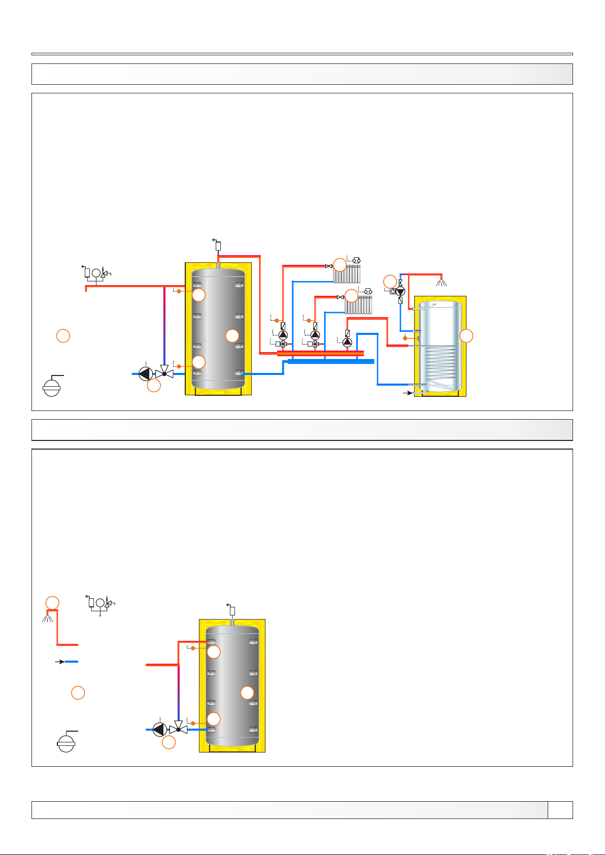
13.9. CONFIGURATION A-2-2
1 - Boiler EKO-CK P + Cm Pelet-set
2 - Accumulation tank
3 - 3-way themostatic mixing valve + pump (P1)
(return flow protection)
4 - Accumulation tank upper temp. sensor (BUFFER1)
5 - Accumulation tank lower temp. sensor (BUFFER2)
6 - Mixing heating circuit
7 - DHW tank
8 - DHW recirculation (P3)
9 - 1. circuit flow sensor (CIRCUIT1) + pump (P4) + actuator (MVAL1)
10 - 2. circuit flow sensor (CIRCUIT2) + pump (P5) + actuator (MVAL2)
11 - DHW tank pump (P2)
12 - DHW tank sensor (DHW)
Temperatures:
Boiler temp.: 80°C (80-90°C)
Tpuf: 80°C (65-80°C)
dTpuf: 10°C (5-30°C)
dTbuf-off: 5°C (3-50°C)
Tdhw: 50°(10-70°C)
dTdhw: 5°C (3-20°C)
Tbuf min.: 20°C (5-85°C)
EKO-CK P
bar
4
1
2
5
3
13.10. CONFIGURATION A-7-0
6
8
6
M M
1 - Boiler EKO-CKB P + Cm Pelet-set
2 - Accumulation tank
3 - 3-way thermostatic mixing valve + pump (P1)
(return flow protection)
4 - Accumulation tank upper temp. sensor (BUFFER1)
5 - Accumulation tank lower temp. sensor (BUFFER2)
6 - DHW tank in the boiler
Temperatures:
Boiler temp.: 80°C (80-90°C) = Tdhw
Tpuf: 80°C (65-80°C)
dTpuf: 10°C (5-30°C)
dTpuf-off: 5°C (3-50°C)
7
EKO-CKB P
6
bar
4
1
2
5
3
Technical instructions REGULATION Cm Pelet-set
25
Page 26
Configurations
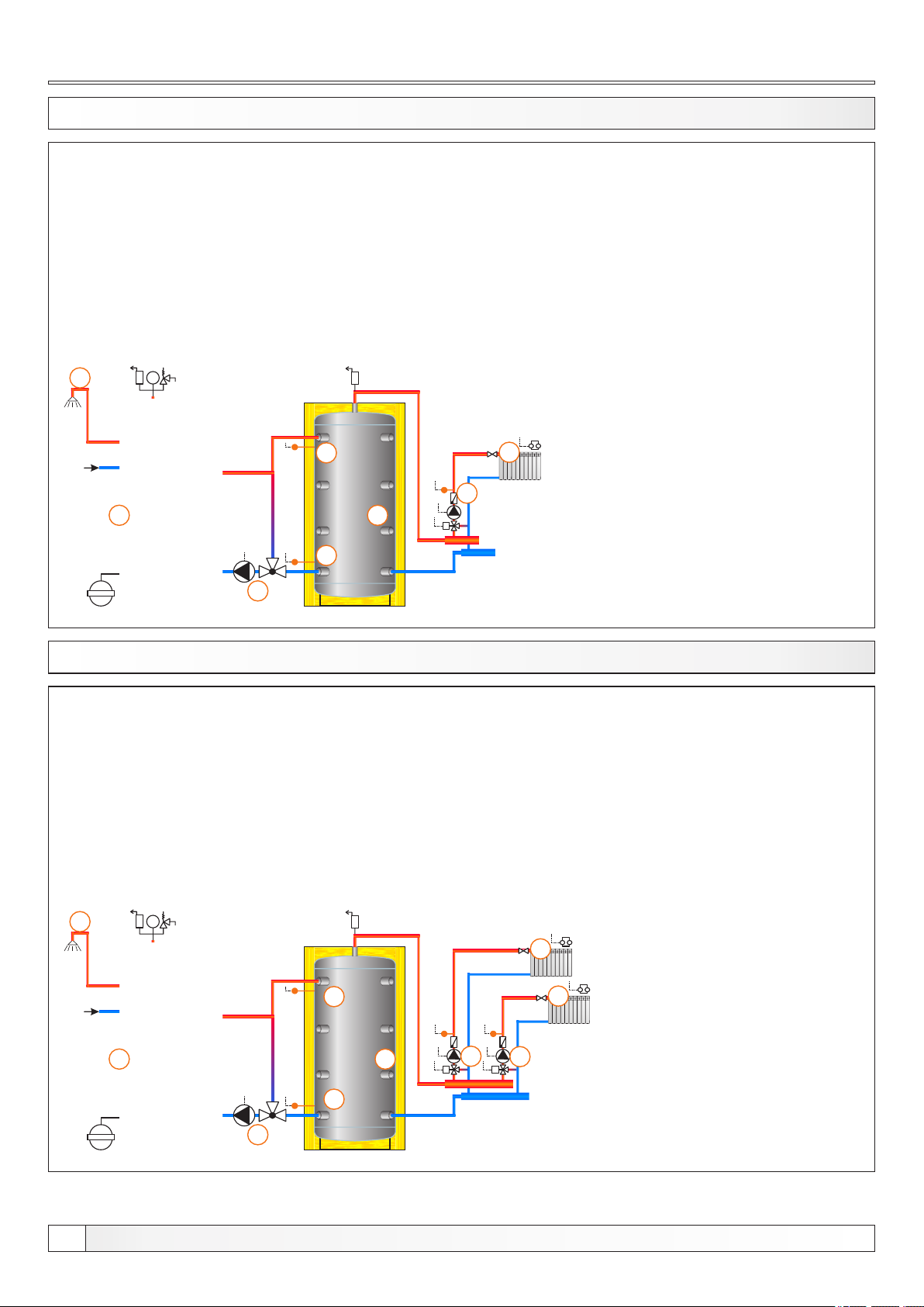
13.11. CONFIGURATION A-7-1
8
bar
4
1
5
EKO-CKB P
1 - Boiler EKO-CKB P + Cm Pelet-set
2 - 2 - Accumulation tank
3 - 3-way thermostatic mixing valve + pump (P1)
(return flow protection)
4 - Accumulation tank upper temp. sensor (BUFFER1)
5 - Accumulation tank lower temp. sensor (BUFFER2)
6 - Mixing heating circuit
7 - 1. mixing circuit temp. sensor (CIRCUIT1) + pump (P4) + actuator (MVAL1)
8 - DHW tank in the boiler
Temperatures:
Boiler temp.: 80°C (80-90°C) = Tdhw
Tpuf: 80°C (65-80°C)
dTpuf: 10°C (5-30°C)
dTpuf-off: 5°C (3-50°C)
Tpuf min.: 20°C (5-85°C)
6
7
2
M
3
13.12. CONFIGURATION A-7-2
9
bar
4
1 - Boiler EKO-CKB P + Cm Pelet-set
2 - 2 - Accumulation tank
3 - 3-way thermostatic mixing valve + pump (P1)
(return flow protection)
4 - Accumulation tank upper temp. sensor (BUFFER1)
5 - Accumulation tank lower temp. sensor (BUFFER2)
6 - Mixing heating circuit
7 - 1. mixing circuit temp. sensor (CIRCUIT1) + pump (P4) + actuator (MVAL1)
8 - 2. mixing circuit temp. sensor (CIRCUIT2) + pump (P5) + actuator (MVAL2)
9 - DHW tank in the boiler
Temperatures:
Boiler temp.: 80°C (80-90°C) = Tdhw
Tpuf: 80°C (65-80°C)
dTpuf: 10°C (5-30°C)
dTpuf-off: 5°C (3-50°C)
Tpuf min.: 20°C (5-85°C)
6
6
EKO-CKB P
26
1
2
8
7
MM
5
3
Technical instructions REGULATION Cm Pelet-set
Page 27
Configurations
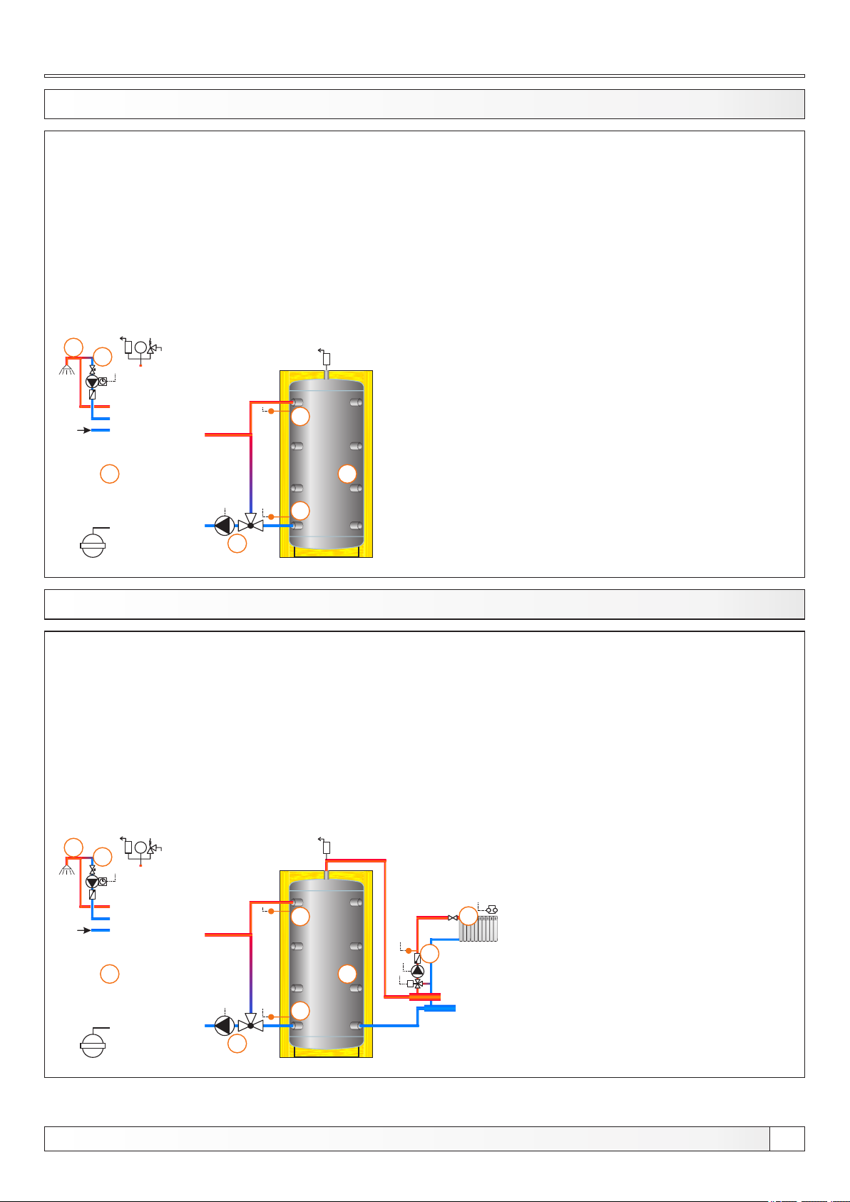
13.13. CONFIGURATION A-8-0
6
bar
7
4
1
5
EKO-CKB P
1 - Boiler EKO-CKB P + Cm Pelet-set
2 - 2 - Accumulation tank
3 - 3-way thermostatic mixing valve + pump (P1)
(return flow protection)
4 - Accumulation tank upper temp. sensor (BUFFER1)
5 - Accumulation tank lower temp. sensor (BUFFER2)
6 - DHW tank in the boiler
7 - DHW tank recirculation (P3)
Temperatures:
Boiler temp.: 80°C (80-90°C) = Tdhw
Tpuf: 80°C (65-80°C)
dTpuf: 10°C (5-30°C)
dTpuf-off: 5°C (3-50°C)
2
3
13.14. CONFIGURATION A-8-1
8
bar
9
4
1
EKO-CKB P
1 - Boiler EKO-CKB P + Cm Pelet-set
2 - 2 - Accumulation tank
3 - 3-way thermostatic mixing valve + pump (P1)
(return flow protection)
4 - Accumulation tank upper temp. sensor (BUFFER1)
5 - Accumulation tank lower temp. sensor (BUFFER2)
6 - Mixing heating circuit
7 - 1. mixing circuit temp. sensor (CIRCUIT1) + pump (P4) + actuator (MVAL1)
8 - DHW tank in the boiler
9 - DHW tank recirculation (P3)
Temperatures:
Boiler temp.: 80°C (80-90°C) = Tdhw
Tpuf: 80°C (65-80°C)
dTpuf: 10°C (5-30°C)
dTpuf-off: 5°C (3-50°C)
Tpuf min.: 20°C (5-85°C)
6
7
2
M
5
3
Technical instructions REGULATION Cm Pelet-set
27
Page 28
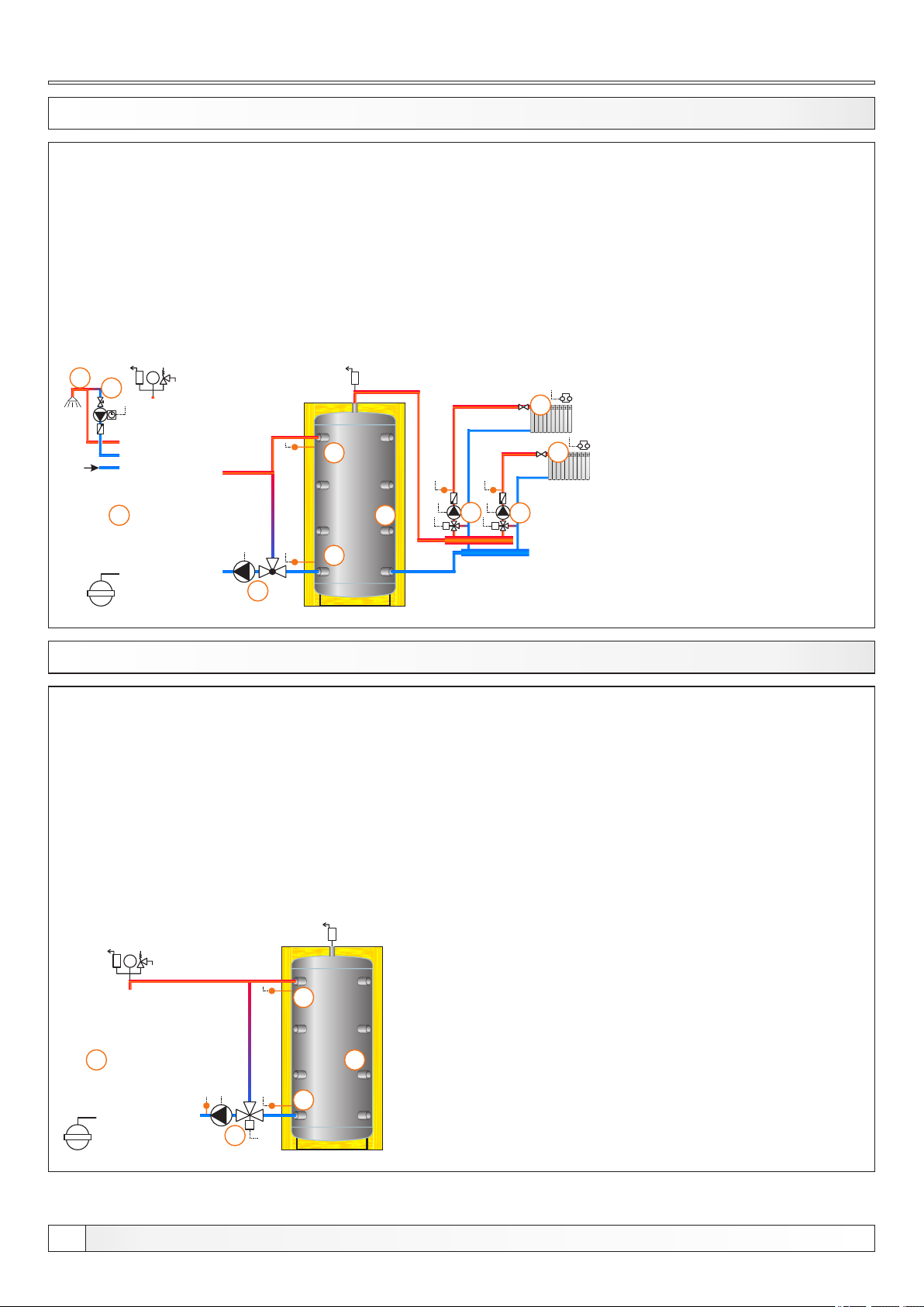
Configurations
13.15. CONFIGURATION A-8-2
9
bar
10
4
1
5
1 - Boiler EKO-CKB P + Cm Pelet-set
2 - 2 - Accumulation tank
3 - 3-way thermostatic mixing valve + pump (P1)
(return flow protection)
4 - Accumulation tank upper temp. sensor (BUFFER1)
5 - Accumulation tank lower temp. sensor (BUFFER2)
6 - Mixing heating circuit
7 - 1. mixing circuit temp. sensor (CIRCUIT1) + pump (P4) + actuator (MVAL1)
8 - Osjetnik 2. miješajućeg kruga (CIRCUIT2) + pumpa (P5) + motorni pogon (MVAL2)
9 - DHW tank in the boiler
10 - DHW tank recirculation (P3)
Temperatures:
Boiler temp.: 80°C (80-90°C) = Tdhw
Tpuf: 80°C (65-80°C)
dTpuf: 10°C (5-30°C)
dTpuf-off: 5°C (3-50°C)
Tpuf min.: 20°C (5-85°C)
6
6
2
8
7
MM
EKO-CKB P
3
13.16. CONFIGURATION B-0-0
bar
4
EKO-CK P
1 - Boiler EKO-CK P + Cm Pelet-set
2 - Accumulation tank
3 - 3-way mixing valve + actuator (MVAL2) + return flow temp. sensor (CIRCUIT2) + pump (P1)
(return flow protection)
4 - Accumulation tank upper temp. sensor (BUFFER1)
5 - Accumulation tank lower temp. sensor (BUFFER2)
Temperatures:
Boiler temp.: 80°C (80-90°C)
Tpuf: 80°C (65-80°C)
dTpuf: 10°C (5-30°C)
dTbuf-off: 5°C (3-50°C)
28
1
2
5
M
3
Technical instructions REGULATION Cm Pelet-set
Page 29
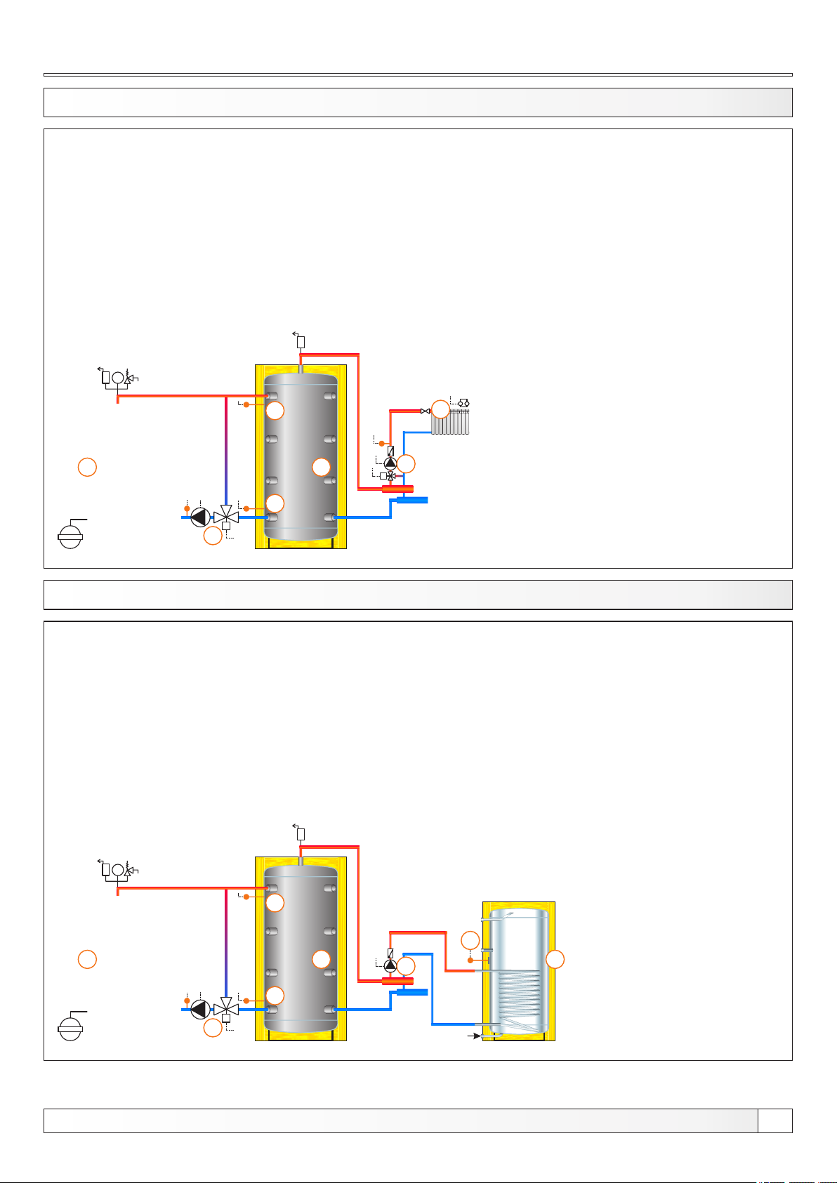
Configurations
13.17. CONFIGURATION B-0-1
bar
4
1
5
M
3
2
EKO-CK P
1 - Boiler EKO-CK P + Cm Pelet-set
2 - Accumulation tank
3 - 3-way mixing valve + actuator (MVAL2) + return flow temp. sensor (CIRCUIT2) + pump (P1)
(return flow protection)
4 - Accumulation tank upper temp. sensor (BUFFER1)
5 - Accumulation tank lower temp. sensor (BUFFER1)
6 - Mixing heating circuit
7 - 1. circuit flow sensor (CIRCUIT1) + pump (P4) + actuator (MVAL1)
Temperatures:
Boiler temp.: 80°C (80-90°C)
Tpuf: 80°C (65-80°C)
dTpuf: 10°C (5-30°C)
dTbuf-off: 5°C (3-50°C)
Tdhw: 50°(10-70°C)
dTdhw: 5°C (3-20°C)
6
7
M
13.18. CONFIGURATION B-1-0
bar
4
1
5
M
3
2
EKO-CK P
1 - Boiler EKO-CK P + Cm Pelet-set
2 - Accumulation tank
3 - 3-way mixing valve + actuator (MVAL2) + return flow temp. sensor (CIRCUIT2) + pump (P1)
(return flow protection)
4 - Accumulation tank upper temp. sensor (BUFFER1)
5 - Accumulation tank lower temp. sensor (BUFFER1)
6 - DHW tank
7 - DHW tank pump (P2)
8 - DHW tank sensor (DHW)
Temperatures:
Boiler temp.: 80°C (80-90°C)
Tpuf: 80°C (65-80°C)
dTpuf: 10°C (5-30°C)
dTbuf-off: 5°C (3-50°C)
Tdhw: 50°(10-70°C)
dTdhw: 5°C (3-20°C)
8
7
6
Technical instructions REGULATION Cm Pelet-set
29
Page 30
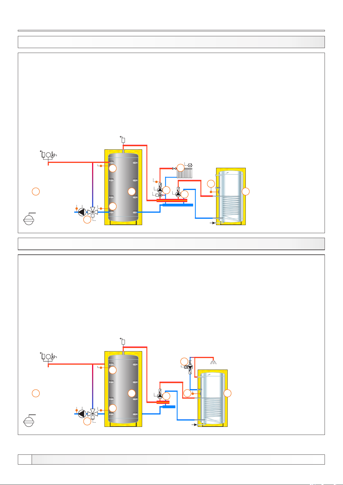
Configurations
13.19. CONFIGURATION B-1-1
bar
4
1
5
M
3
2
EKO-CK P
1 - Boiler EKO-CK P + Cm Pelet-set
2 - Accumulation tank
3 - 3-way mixing valve + actuator (MVAL2) + return flow temp. sensor (CIRCUIT2) + pump (P1)
(return flow protection)
4 - Accumulation tank upper temp. sensor (BUFFER1)
5 - Accumulation tank lower temp. sensor (BUFFER2)
6 - Mixing heating circuit
7 - DHW tank
8 - 1. circuit flow sensor (CIRCUIT1) + pump (P4) + actuator (MVAL1)
9 - DHW tank pump (P2)
10 - DHW tank sensor (DHW)
Temperatures:
Boiler temp.: 80°C (80-90°C)
Tpuf: 80°C (65-80°C)
dTpuf: 10°C (5-30°C)
dTbuf-off: 5°C (3-50°C)
Tdhw: 50°(10-70°C)
dTdhw: 5°C (3-20°C)
Tbuf min.: 20°C (5-85°C)
6
10
8
M
9
7
13.20. CONFIGURATION B-2-0
bar
4
1
5
M
3
2
EKO-CK P
1 - Boiler EKO-CK P + Cm Pelet-set
2 - Accumulation tank
3 - 3-way mixing valve + actuator (MVAL2) + return flow temp. sensor (CIRCUIT2) + pump (P1)
(return flow protection)
4 - Accumulation tank upper temp. sensor (BUFFER1)
5 - Accumulation tank lower temp. sensor (BUFFER2)
6 - DHW tank
7 - DHW recirculation (P3)
8 - DHW tank pump (P2)
9 - DHW tank sensor (DHW)
Temperatures:
Boiler temp.: 80°C (80-90°C)
Tpuf: 80°C (65-80°C)
dTpuf: 10°C (5-30°C)
dTbuf-off: 5°C (3-50°C)
Tdhw: 50°(10-70°C)
dTdhw: 5°C (3-20°C)
7
8
9
6
30
Technical instructions REGULATION Cm Pelet-set
Page 31
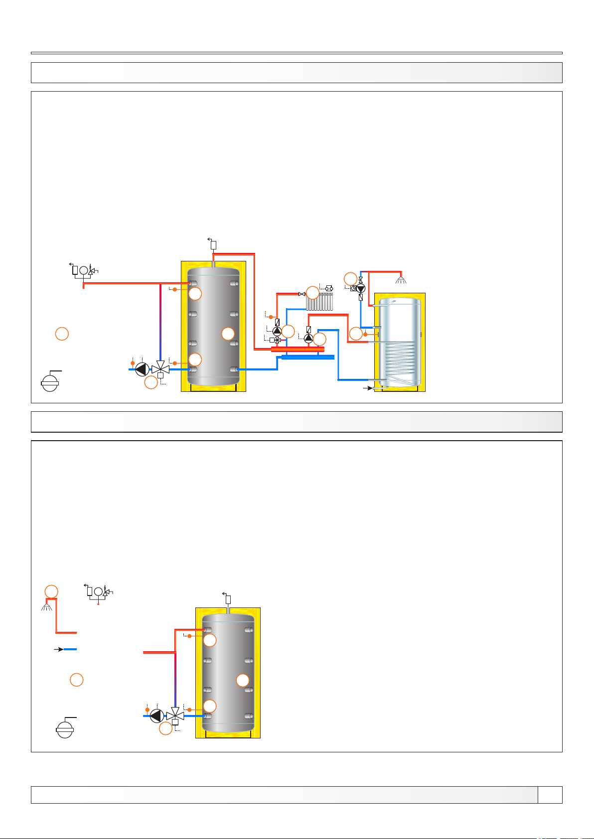
Configurations
13.21. CONFIGURATION B-2-1
bar
4
1
5
M
3
2
EKO-CK P
1 - Boiler EKO-CK P + Cm Pelet-set
2 - Accumulation tank
3 - 3-way mixing valve + actuator (MVAL2) + return flow temp. sensor (CIRCUIT2) + pump (P1)
(return flow protection)
4 - Accumulation tank upper temp. sensor (BUFFER1)
5 - Accumulation tank lower temp. sensor (BUFFER2)
6 - Mixing heating circuit
7 - DHW tank
8 - DHW recirculation (P3)
9 - 1. circuit flow sensor (CIRCUIT1) + pump (P4) + actuator (MVAL1)
10 - DHW tank pump (P2)
11 - DHW tank sensor (DHW)
Temperatures:
Boiler temp.: 80°C (80-90°C)
Tpuf: 80°C (65-80°C)
dTpuf: 10°C (5-30°C)
dTbuf-off: 5°C (3-50°C)
Tdhw: 50°(10-70°C)
dTdhw: 5°C (3-20°C)
Tbuf min.: 20°C (5-85°C)
8
6
9
M
10
11
HV
13.22. CONFIGURATION B-7-0
6
bar
4
1
5
M
3
EKO-CKB P
1 - Boiler EKO-CKB P + Cm Pelet-set
2 - Accumulation tank
3 - 3-way mixing valve + actuator (MVAL2) + return flow temp. sensor (CIRCUIT2) + pump (P1)
(return flow protection)
4 - Accumulation tank upper temp. sensor (BUFFER1)
5 - Accumulation tank lower temp. sensor (BUFFER2)
6 - DHW tank in the boiler
Temperatures:
Boiler temp.: 80°C (80-90°C) = Tdhw
Tpuf: 80°C (65-80°C)
dTpuf: 10°C (5-30°C)
dTbuf-off: 5°C (3-50°C)
Tbuf min.: 20°C (5-85°C)
2
Technical instructions REGULATION Cm Pelet-set
31
Page 32
Configurations
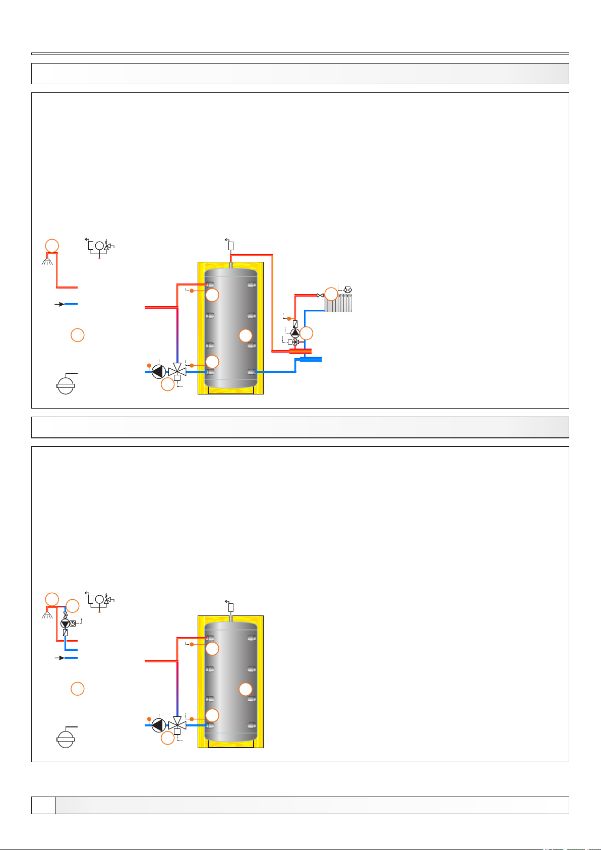
13.23. CONFIGURATION B-7-1
8
bar
4
1
5
M
3
EKO-CKB P
1 - Boiler EKO-CK P + Cm Pelet-set
2 - Accumulation tank
3 - 3-way mixing valve + actuator (MVAL2) + return flow temp. sensor (CIRCUIT2) + pump (P1)
(return flow protection)
4 - Accumulation tank upper temp. sensor (BUFFER1)
5 - Accumulation tank lower temp. sensor (BUFFER2)
6 - Mixing heating circuit
7 - 1. circuit flow sensor (CIRCUIT1) + pump (P4) + actuator (MVAL1)
8 - DHW tank in the boiler
Temperatures:
Boiler temp.: 80°C (80-90°C) = Tdhw
Tpuf: 80°C (65-80°C)
dTpuf: 10°C (5-30°C)
dTbuf-off: 5°C (3-50°C)
Tdhw: 50°(10-70°C)
dTdhw: 5°C (3-20°C)
Tbuf min.: 20°C (5-85°C)
6
2
7
M
13.24. CONFIGURATION B-8-0
6
bar
7
4
1
5
M
3
EKO-CKB P
1 - Boiler EKO-CK P + Cm Pelet-set
2 - Accumulation tank
3 - 3-way mixing valve + actuator (MVAL2) + return flow temp. sensor (CIRCUIT2) + pump (P1)
(return flow protection)
4 - Accumulation tank upper temp. sensor (BUFFER1)
5 - Accumulation tank lower temp. sensor (BUFFER2)
7 - DHW tank in the boiler
8 - DHW tank recirculation (P3)
Temperatures:
Boiler temp.: 80°C (80-90°C) = Tdhw
Tpuf: 80°C (65-80°C)
dTpuf: 10°C (5-30°C)
dTbuf-off: 5°C (3-50°C)
Tdhw: 50°(10-70°C)
dTdhw: 5°C (3-20°C)
Tbuf min.: 20°C (5-85°C)
2
32
Technical instructions REGULATION Cm Pelet-set
Page 33
Configurations
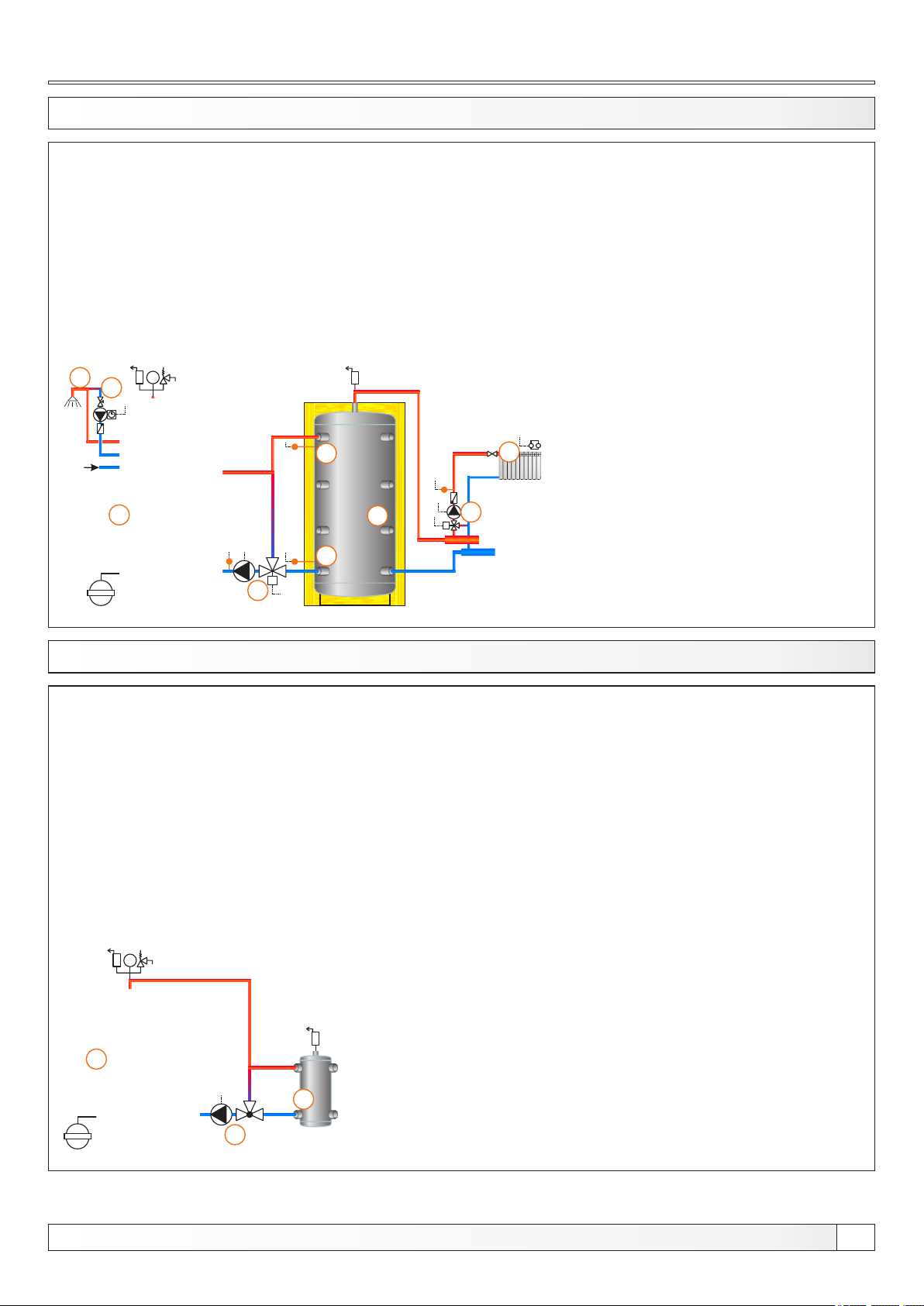
13.25. CONFIGURATION B-8-1
8
bar
9
4
1
5
M
3
EKO-CKB P
1 - Boiler EKO-CKB P + Cm Pelet-set
2 - Accumulation tank
3 - 3-way mixing valve + actuator (MVAL2) + return flow temp. sensor (CIRCUIT2) + pump (P1)
(return flow protection)
4 - Accumulation tank upper temp. sensor (BUFFER1)
5 - Accumulation tank lower temp. sensor (BUFFER2)
6 - Mixing heating circuit
7 - 1. circuit flow sensor (CIRCUIT1) + pump (P4) + actuator (MVAL1)
8 - DHW tank in the boiler in the boiler
9 - DHW tank recirculation (P3)
Temperatures:
Boiler temp.: 80°C (80-90°C) = Tdhw
Tpuf: 80°C (65-80°C)
dTpuf: 10°C (5-30°C)
dTbuf-off: 5°C (3-50°C)
Tdhw: 50°(10-70°C)
dTdhw: 5°C (3-20°C)
Tbuf min.: 20°C (5-85°C)
6
2
7
M
13.26. CONFIGURATION C-0-0
bar
1
2
1 - Boiler EKO-CK P + Cm Pelet-set
2 - Hydraulic crossover (CRO)
3 - 3-way themostatic mixing valve + pump (P1)
(return flow protection)
Temperatures:
Boiler temp.: 80°C (70-90°C)
EKO-CK P
3
Technical instructions REGULATION Cm Pelet-set
33
Page 34
Configurations
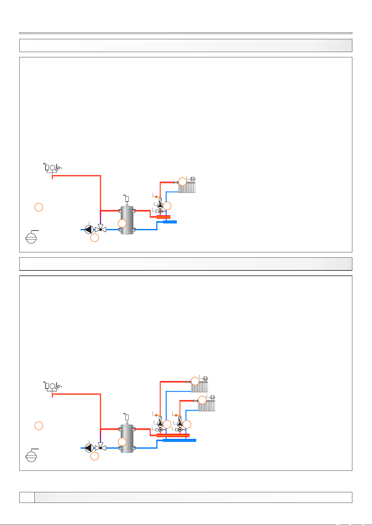
13.27. CONFIGURATION C-0-1
bar
1
2
1 - Boiler EKO-CK P + Cm Pelet-set
2 - Hydraulic crossover (CRO)
3 - 3-way themostatic mixing valve + pump (P1)
(return flow protection)
4 - Mixing heating circuit
5 - 1. circuit flow sensor (CIRCUIT1) + pump (P4) + actuator (MVAL1)
Temperatures:
Boiler temp.: 80°C (70-90°C)
4
5
M
EKO-CK P
3
13.28. CONFIGURATION C-0-2
bar
1 - Boiler EKO-CK P + Cm Pelet-set
2 - Hydraulic crossover (CRO)
3 - 3-way themostatic mixing valve + pump (P1)
(return flow protection)
4 - Mixing heating circuit
5 - 1. circuit flow sensor (CIRCUIT1) + pump (P4) + actuator (MVAL1)
6 - 2. circuit flow sensor (CIRCUIT2) + pump (P5) + actuator (MVAL2)
Temperatures:
Boiler temp.: 80°C (70-90°C)
4
4
EKO-CK P
34
1
6
5
MM
2
3
Technical instructions REGULATION Cm Pelet-set
Page 35
Configurations
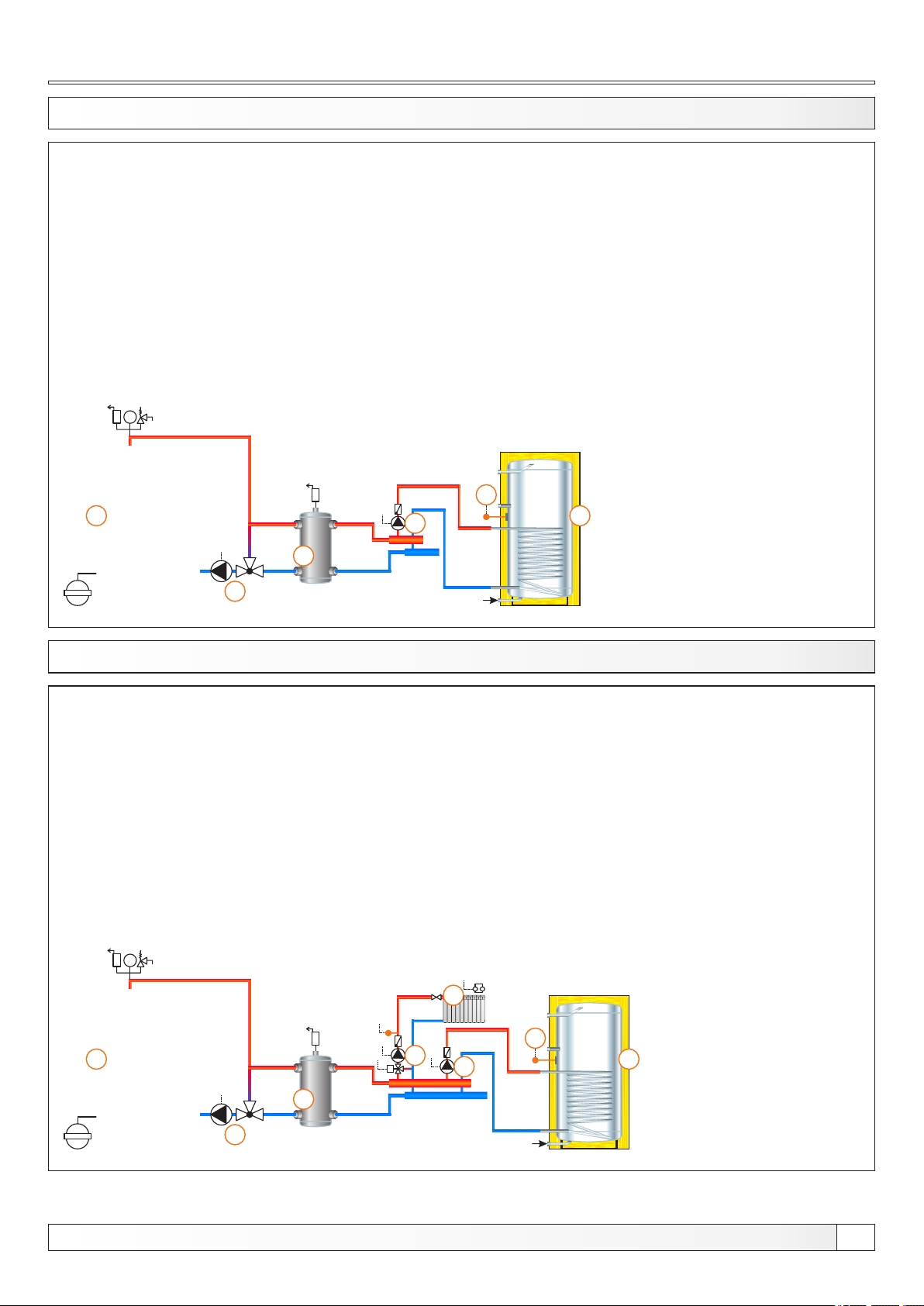
13.29. CONFIGURATION C-1-0
bar
1
2
1 - Boiler EKO-CK P + Cm Pelet-set
2 - Hydraulic crossover (CRO)
3 - 3-way themostatic mixing valve + pump (P1)
(return flow protection)
4 - DHW tank
5 - DHW tank pump (P2)
6 - DHW tank sensor (DHW)
Temperatures:
Boiler temp.: 80°C (70-90°C)
Tdhw: 50°C (10-70°C)
dTdhw: 5°C (3-20°C)
6
5
4
EKO-CK P
3
13.30. CONFIGURATION C-1-1
bar
1
1 - Boiler EKO-CK P + Cm Pelet-set
2 - Hydraulic crossover (CRO)
3 - 3-way themostatic mixing valve + pump (P1)
(return flow protection)
4 - Mixing heating circuit
5 - DHW tank
6 - 1. circuit flow sensor (CIRCUIT1) + pump (P4) + actuator (MVAL1)
7 - DHW tank pump (P2)
8 - DHW tank sensor (DHW)
Temperatures:
Boiler temp.: 80°C (70-90°C)
Tdhw: 50°C (10-70°C)
dTdhw: 5°C (3-20°C)
4
8
6
M
7
5
EKO-CK P
2
3
Technical instructions REGULATION Cm Pelet-set
35
Page 36
Configurations
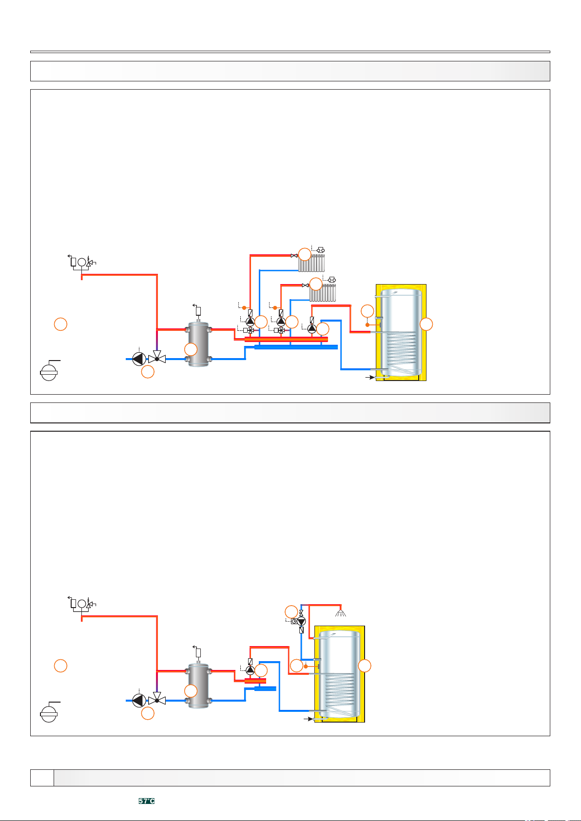
13.31. CONFIGURATION C-1-2
bar
1
2
1 - Boiler EKO-CK P + Cm Pelet-set
2 - Hydraulic crossover (CRO)
3 - 3-way themostatic mixing valve + pump (P1)
(return flow protection)
4 - Mixing heating circuit (2x)
5 - DHW tank
6 - 1. circuit flow sensor (CIRCUIT1) + pump (P4) + actuator (MVAL1)
7 - 2. circuit flow sensor (CIRCUIT2) + pump (P5) + actuator (MVAL2)
8 - DHW tank pump (P2)
9 - DHW tank sensor (DHW)
Temperatures:
Boiler temp.: 80°C (70-90°C)
Tdhw: 50°C (10-70°C)
dTdhw: 5°C (3-20°C)
4
4
9
67
MM
8
5
EKO-CK P
3
13.32. CONFIGURATION C-2-0
bar
1 - Boiler EKO-CK P + Cm Pelet-set
2 - Hydraulic crossover (CRO)
3 - 3-way themostatic mixing valve + pump (P1)
(return flow protection)
4 - DHW tank
5 - DHW recirculation (P3)
6 - DHW tank pump (P2)
7 - DHW tank sensor (DHW)
Temperatures:
Boiler temp.: 80°C (70-90°C)
Tdhw: 50°C (10-70°C)
dTdhw: 5°C (3-20°C)
5
EKO-CK P
36
1
6
7
4
2
3
Technical instructions REGULATION Cm Pelet-set
Page 37
Configurations
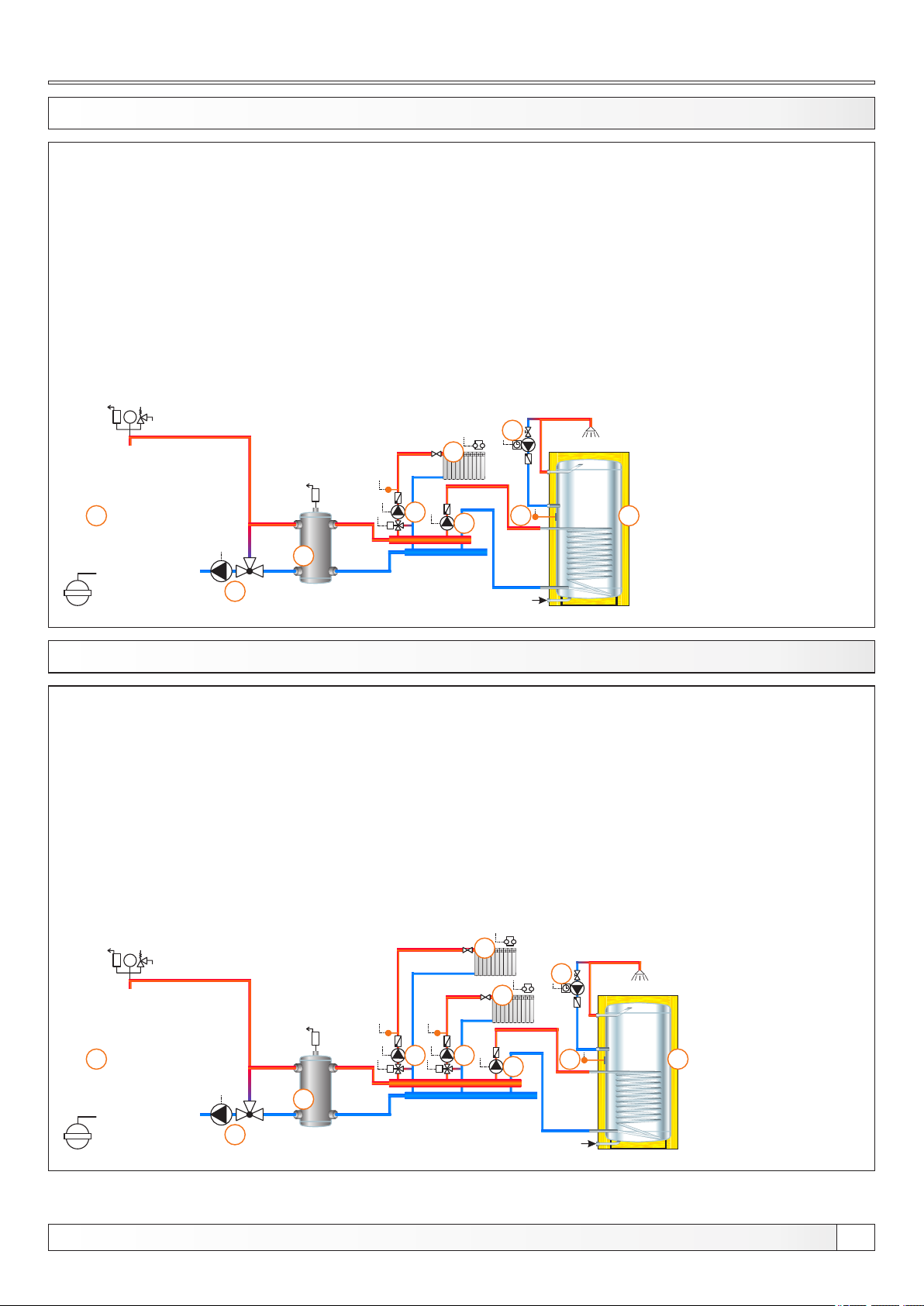
13.33. CONFIGURATION C-2-1 EKO-CK P
1 - Boiler EKO-CK P + Cm Pelet-set
2 - Hydraulic crossover (CRO)
3 - 3-way themostatic mixing valve + pump (P1)
(return flow protection)
4 - Mixing heating circuit
5 - DHW tank
6 - DHW recirculation (P3)
7 - 1. circuit flow sensor (CIRCUIT1) + pump (P4) + actuator (MVAL1)
8 - DHW tank pump (P2)
9 - DHW tank sensor (DHW)
Temperatures:
Boiler temp.: 80°C (70-90°C)
Tdhw: 50°C (10-70°C)
dTdhw: 5°C (3-20°C)
bar
6
4
1
2
3
13.34. CONFIGURATION C-2-2
bar
7
M
8
1 - Boiler EKO-CK P + Cm Pelet-set
2 - Hydraulic crossover (CRO)
3 - 3-way themostatic mixing valve + pump (P1)
(return flow protection)
4 - Mixing heating circuit
5 - DHW tank
6 - DHW recirculation (P3)
7 - 1. circuit flow sensor (CIRCUIT1) + pump (P4) + actuator (MVAL1)
8 - 2. circuit flow sensor (CIRCUIT2) + pump (P5) + actuator (MVAL2)
9 - DHW tank pump (P2)
10 - DHW tank sensor (DHW)
Temperatures:
Boiler temp.: 80°C (70-90°C)
Tdhw: 50°C (10-70°C)
dTdhw: 5°C (3-20°C)
9
5
4
6
4
EKO-CK P
1
8
MM
2
3
Technical instructions REGULATION Cm Pelet-set
7
9
10
5
37
Page 38
Configurations
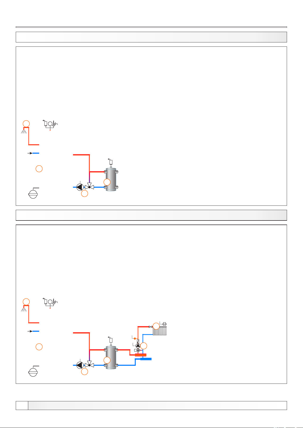
13.35. CONFIGURATION C-7-0
4
bar
1
2
1 - Boiler EKO-CKB P + Cm Pelet-set
2 - Hydraulic crossover (CRO)
3 - 3-way themostatic mixing valve + pump (P1)
(return flow protection)
4 - DHW tank in the boiler
Temperatures:
Boiler temp.: 80°C (70-90°C) - Tdhw
EKO-CKB P
3
13.36. CONFIGURATION C-7-1
6
bar
1 - Boiler EKO-CKB P + Cm Pelet-set
2 - Hydraulic crossover (CRO)
3 - 3-way themostatic mixing valve + pump (P1)
(return flow protection)
4 - Mixing heating circuit
5 - 1. circuit flow sensor (CIRCUIT1) + pump (P4) + actuator (MVAL1)
6 - DHW tank in the boiler
Temperatures:
Boiler temp.: 80°C (70-90°C) - Tdhw
4
EKO-CKB P
38
1
5
M
2
3
Technical instructions REGULATION Cm Pelet-set
Page 39
Configurations
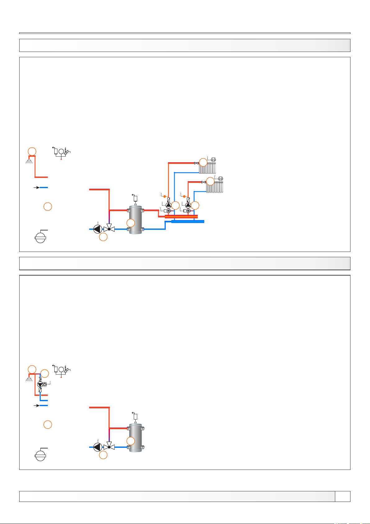
13.37. CONFIGURATION C-7-2
7
bar
1
2
1 - Boiler EKO-CKB P + Cm Pelet-set
2 - Hydraulic crossover (CRO)
3 - 3-way themostatic mixing valve + pump (P1)
(return flow protection)
4 - Mixing heating circuit
5 - 1. circuit flow sensor (CIRCUIT1) + pump (P4) + actuator (MVAL1)
6 - 2. circuit flow sensor (CIRCUIT2) + pump (P5) + actuator (MVAL2)
7 - DHW tank in the boiler
Temperatures:
Boiler temp.: 80°C (70-90°C) = Tdhw
4
4
6
5
MM
EKO-CKB P
3
13.38. CONFIGURATION C-8-0
4
bar
5
1 - Boiler EKO-CK P + Cm Pelet-set
2 - Hydraulic crossover (CRO)
3 - 3-way themostatic mixing valve + pump (P1)
(return flow protection)
4 - DHW tank in ther boiler
5 - DHW tank recirculation (P3)
Temperatures:
Boiler temp.: 80°C (70-90°C) = Tdhw
EKO-CKB P
1
2
3
Technical instructions REGULATION Cm Pelet-set
39
Page 40
Configurations
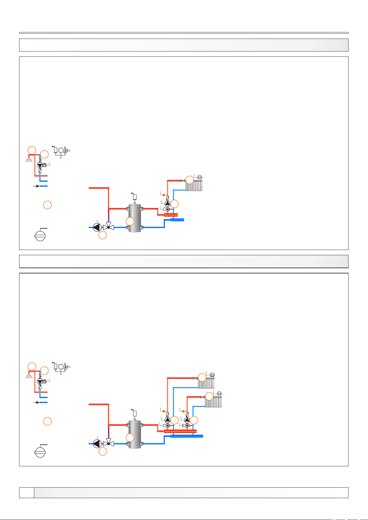
13.39. CONFIGURATION C-8-1
6
bar
7
1
2
1 - Boiler EKO-CKB P + Cm Pelet-set
2 - Hydraulic crossover (CRO)
3 - 3-way themostatic mixing valve + pump (P1)
(return flow protection)
4 - Mixing heating circuit
5 - 1. circuit flow sensor (CIRCUIT1) + pump (P4) + actuator (MVAL1)
6 - DHW tank in the boiler
7 - DHW tank recirculation (P3)
Temperatures:
Boiler temp.: 80°C (70-90°C) = Tdhw
4
5
M
EKO-CKB P
3
13.40. CONFIGURATION C-8-2
7
bar
8
1 - Boiler EKO-CKB P + Cm Pelet-set
2 - Hydraulic crossover (CRO)
3 - 3-way themostatic mixing valve + pump (P1)
(return flow protection)
4 - Mixing heating circuit
5 - 1. circuit flow sensor (CIRCUIT1) + pump (P4) + actuator (MVAL1)
6 - 2. circuit flow sensor (CIRCUIT2) + pump (P5) + actuator (MVAL2)
7 - DHW tank in the boiler
8 - DHW tank recirculation (P3)
Temperatures:
Boiler temp.: 80°C (70-90°C) = Tdhw
4
4
EKO-CKB P
40
1
6
5
MM
2
3
Technical instructions REGULATION Cm Pelet-set
Page 41
Configurations
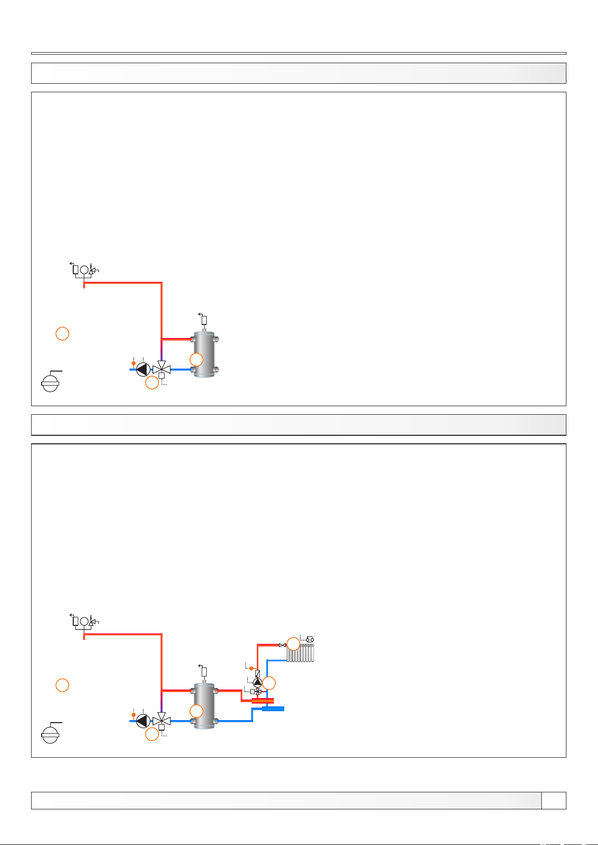
13.41. CONFIGURATION D-0-0
bar
1
2
M
3
EKO-CK P
1 - Boiler EKO-CK P + Cm Pelet-set
2 - Hydraulic crossover (CRO)
3 - 3-way mixing valve + actuator (MVAL2) + return flow temp. sensor (CIRCUIT2) + pump (P1)
(return flow protection)
Temperatures:
Boiler temp.: 80°C (70-90°C)
13.42. CONFIGURATION D-0-1
bar
1
2
M
3
1 - Boiler EKO-CK P + Cm Pelet-set
2 - Hydraulic crossover (CRO)
3 - 3-way mixing valve + actuator (MVAL2) + return flow temp. sensor (CIRCUIT2) + pump (P1)
(return flow protection)
4 - Mixing heating circuit
5 - 1. circuit flow sensor (CIRCUIT1) + pump (P4) + actuator (MVAL1)
Temperatures:
Boiler temp.: 80°C (70-90°C)
4
5
M
EKO-CK P
Technical instructions REGULATION Cm Pelet-set
41
Page 42
Configurations
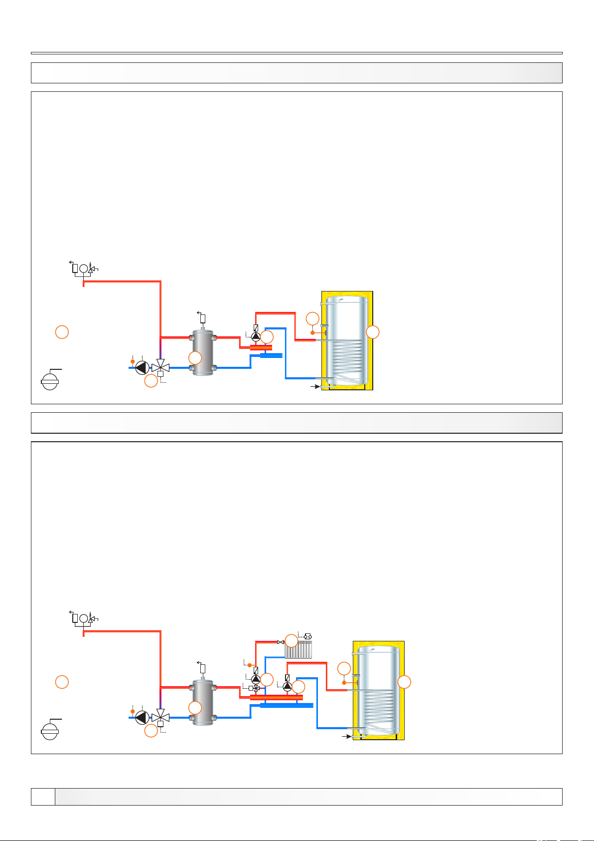
13.43. CONFIGURATION D-1-0
bar
1
2
M
3
EKO-CK P
1 - Boiler EKO-CK P + Cm Pelet-set
2 - Hydraulic crossover (CRO)
3 - 3-way mixing valve + actuator (MVAL2) + return flow temp. sensor (CIRCUIT2) + pump (P1)
(return flow protection)
4 - DHW tank
7 - DHW tank pump (P2)
8 - DHW tank sensor (DHW)
Temperatures:
Boiler temp.: 80°C (70-90°C)
Tdhw: 50°C (10-70°C)
dTdhw: 5°C (3-20°C)
6
5
4
13.44. CONFIGURATION D-1-1
bar
1
2
M
3
1 - Boiler EKO-CK P + Cm Pelet-set
2 - Hydraulic crossover (CRO)
3 - 3-way mixing valve + actuator (MVAL2) + return flow temp. sensor (CIRCUIT2) + pump (P1)
(return flow protection)
4 - Mixing heating circuit
5 - DHW tank
6 - 1. circuit flow sensor (CIRCUIT1) + pump (P4) + actuator (MVAL1)
7 - DHW tank pump (P2)
8 - DHW tank sensor (DHW)
Temperatures:
Boiler temp.: 80°C (70-90°C)
Tdhw: 50°C (10-70°C)
dTdhw: 5°C (3-20°C)
4
8
6
M
7
5
EKO-CK P
42
Technical instructions REGULATION Cm Pelet-set
Page 43
Configurations
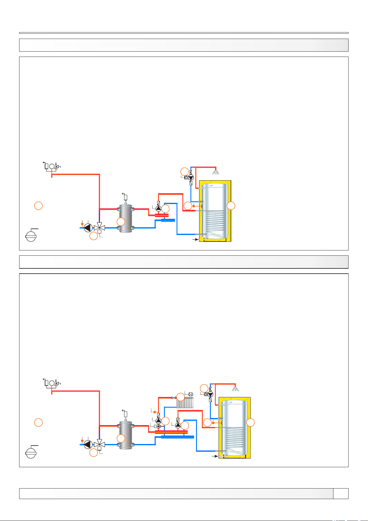
13.45. CONFIGURATION D-2-0
bar
1
2
M
3
EKO-CK P
1 - Boiler EKO-CK P + Cm Pelet-set
2 - Hydraulic crossover (CRO)
3 - 3-way mixing valve + actuator (MVAL2) + return flow temp. sensor (CIRCUIT2) + pump (P1)
(return flow protection)
4 - DHW tank
5 - DHW recirculation (P3)
6 - DHW tank pump (P2)
7 - DHW tank sensor (DHW)
Temperatures:
Boiler temp.: 80°C (70-90°C)
Tdhw: 50°C (10-70°C)
dTdhw: 5°C (3-20°C)
5
6
7
4
13.46. CONFIGURATION D-2-1
bar
1
2
M
3
1 - Boiler EKO-CK P + Cm Pelet-set
2 - Hydraulic crossover (CRO)
3 - 3-way mixing valve + actuator (MVAL2) + return flow temp. sensor (CIRCUIT2) + pump (P1)
(return flow protection)
4 - Mixing heating circuit
5 - DHW tank
6 - DHW recirculation (P3)
7 - 1. circuit flow sensor (CIRCUIT1) + pump (P4) + actuator (MVAL1)
8 - DHW tank pump (P2)
9 - DHW tank sensor (DHW)
Temperatures:
Boiler temp.: 80°C (70-90°C)
Tdhw: 50°C (10-70°C)
dTdhw: 5°C (3-20°C)
6
4
7
M
8
9
5
EKO-CK P
Technical instructions REGULATION Cm Pelet-set
43
Page 44
Configurations
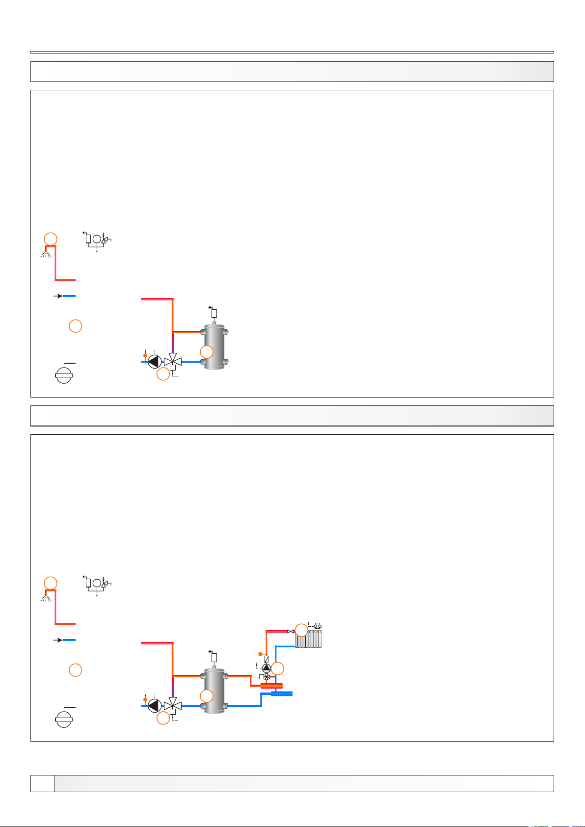
13.47. CONFIGURATION D-7-0
4
bar
1
2
M
3
EKO-CKB P
1 - Boiler EKO-CKB P + Cm Pelet-set
2 - Hydraulic crossover (CRO)
3 - 3-way mixing valve + actuator (MVAL2) + return flow temp. sensor (CIRCUIT2) + pump (P1)
(return flow protection)
4 - DHW tank in the boiler
Temperatures:
Boiler temp.: 80°C (70-90°C) = Tdhw
13.48. CONFIGURATION D-7-1
6
bar
1
2
M
3
3
EKO-CKB P
1 - Boiler EKO-CKB P + Cm Pelet-set
2 - Hydraulic crossover (CRO)
3 - 3-way mixing valve + actuator (MVAL2) + return flow temp. sensor (CIRCUIT2) + pump (P1)
(return flow protection)
4 - Mixing heating circuit
5 - 1. circuit flow sensor (CIRCUIT1) + pump (P4) + actuator (MVAL1)
6 - DHW tank in the boiler
Temperatures:
Boiler temp.: 80°C (70-90°C) = Tdhw
4
5
M
44
Technical instructions REGULATION Cm Pelet-set
Page 45
Configurations
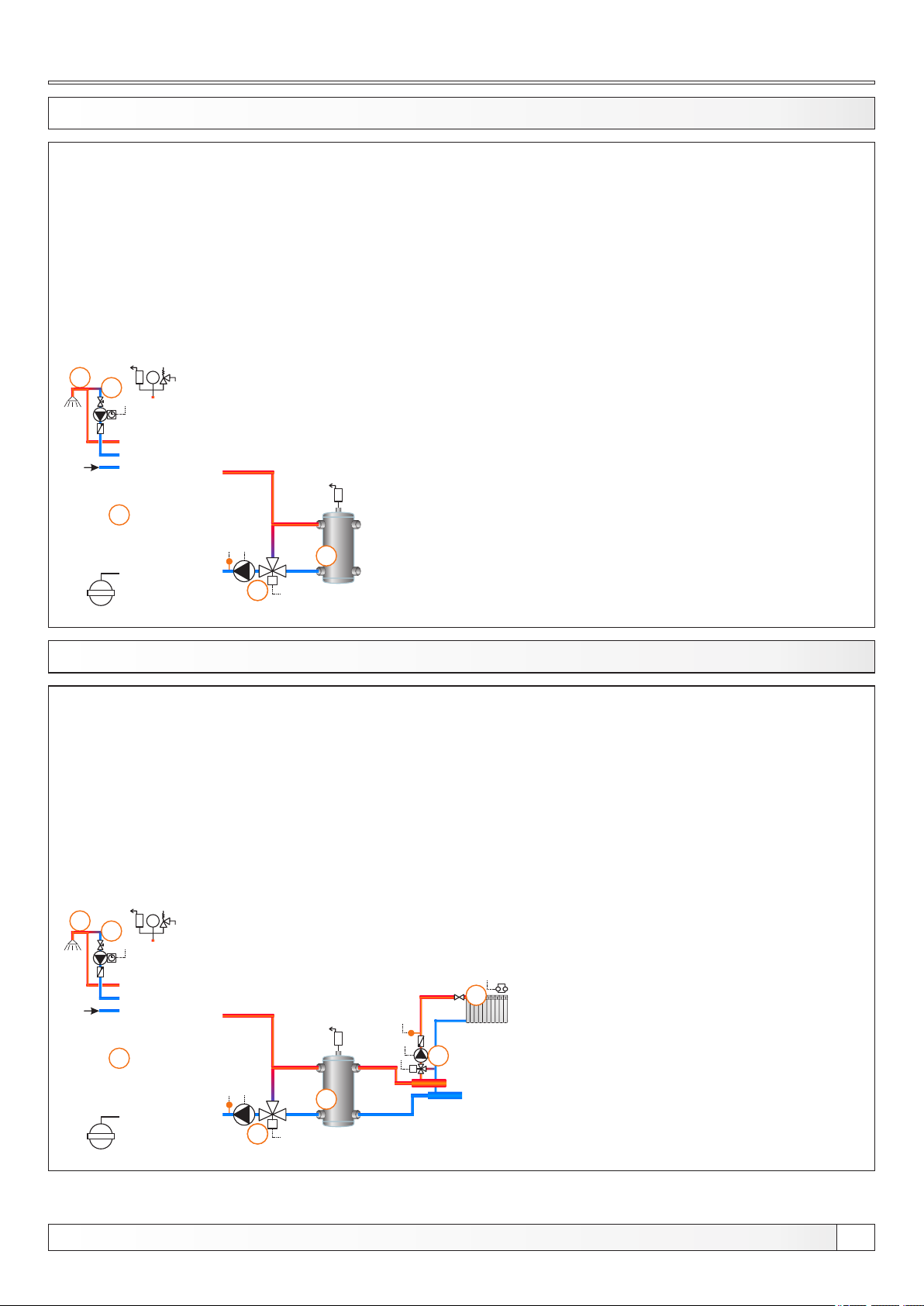
13.49. CONFIGURATION D-8-0
4
bar
5
1
2
M
3
3
EKO-CKB P
1 - Boiler EKO-CKB P + Cm Pelet-set
2 - Hydraulic crossover (CRO)
3 - 3-way mixing valve + actuator (MVAL2) + return flow temp. sensor (CIRCUIT2) + pump (P1)
(return flow protection)
4 - DHW tank in the boiler
5 - DHW tank recirculation (P3)
Temperatures:
Boiler temp.: 80°C (70-90°C) = Tdhw
13.50. CONFIGURATION D-8-1
6
bar
7
1
2
M
3
3
EKO-CKB P
1 - Boiler EKO-CKB P + Cm Pelet-set
2 - Hydraulic crossover (CRO)
3 - 3-way mixing valve + actuator (MVAL2) + return flow temp. sensor (CIRCUIT2) + pump (P1)
(return flow protection)
4 - Mixing heating circuit
5 - 1. circuit flow sensor (CIRCUIT1) + pump (P4) + actuator (MVAL1)
6 - DHW tank in the boiler
7 - DHW tank recirculaton (P3)
Temperatures:
Boiler temp.: 80°C (70-90°C) = Tdhw
4
5
M
Technical instructions REGULATION Cm Pelet-set
45
Page 46
Configurations
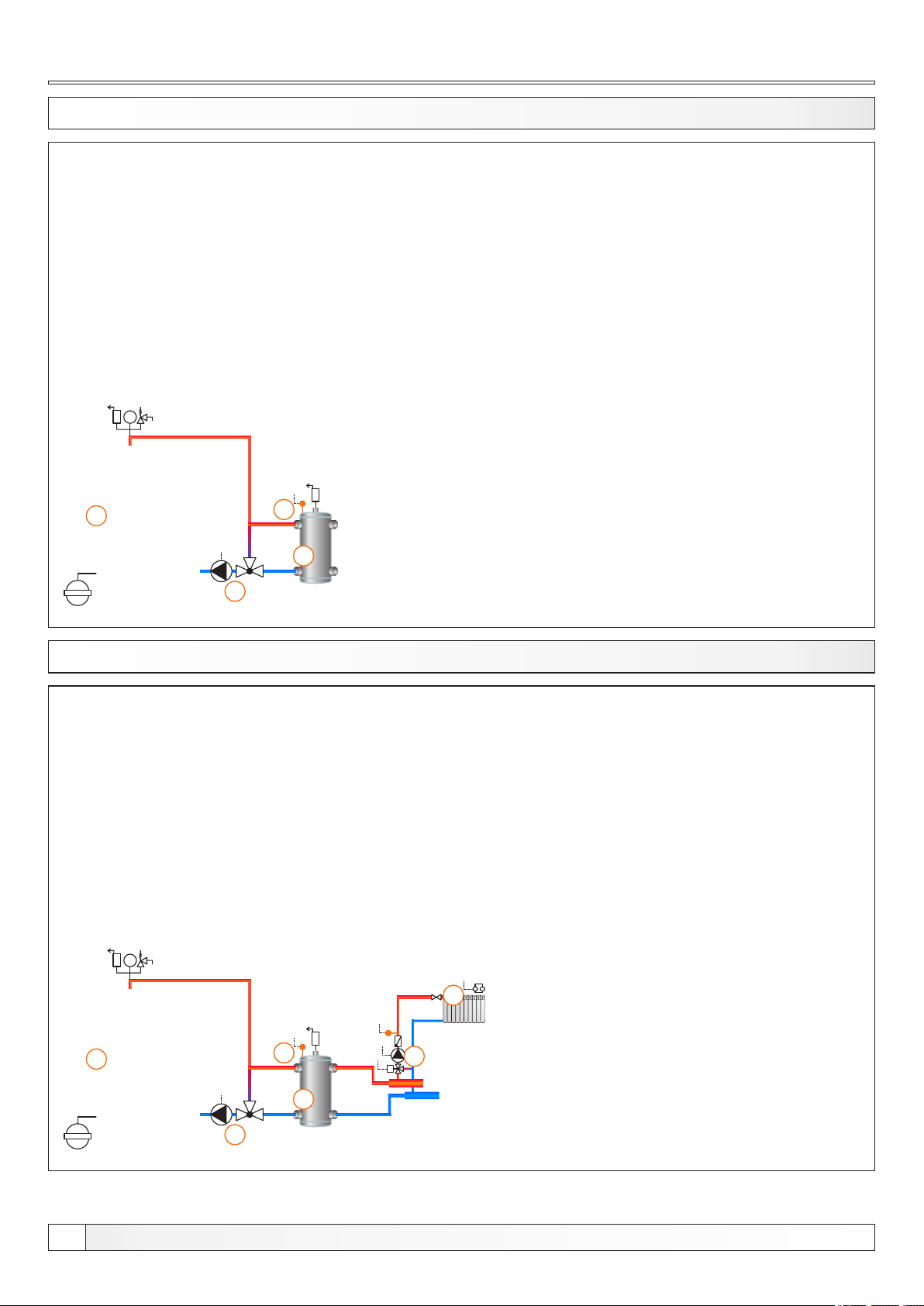
13.51. CONFIGURATION E-0-0
bar
1
4
2
1 - Boiler EKO-CK P + Cm Pelet-set
2 - Hydraulic crossover (CRO)
3 - 3-way themostatic mixing valve + pump (P1)
(return flow protection)
4 - CRO temp. sensor (BUFFER1)
Temperatures:
Boiler temp.: 80°C (70-90°C)
CRO temp.: 75°C (65-80°C)
EKO-CK P
3
13.52. CONFIGURATION E-0-1
bar
1 - Boiler EKO-CK P + Cm Pelet-set
2 - Hydraulic crossover (CRO)
3 - 3-way themostatic mixing valve + pump (P1)
(return flow protection)
4 - CRO temp. sensor (BUFFER1)
5 - Mixing heating circuit
6 - 1. circuit flow sensor (CIRCUIT1) + pump (P4) + actuator (MVAL1)
Temperatures:
Boiler temp.: 80°C (70-90°C)
CRO temp.: 75°C (65-80°C)
5
EKO-CK P
46
1
4
6
M
2
3
Technical instructions REGULATION Cm Pelet-set
Page 47
Configurations
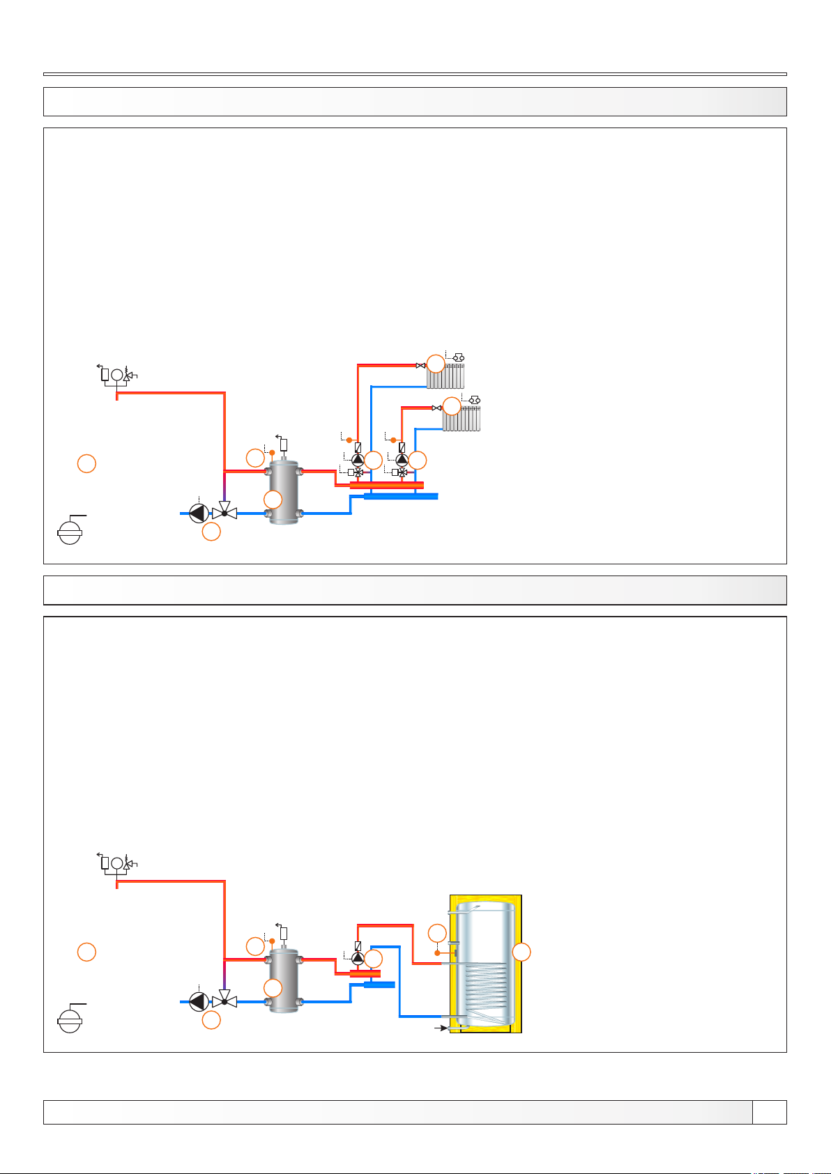
13.53. CONFIGURATION E-0-2
bar
1
4
2
1 - Boiler EKO-CK P + Cm Pelet-set
2 - Hydraulic crossover (CRO)
3 - 3-way themostatic mixing valve + pump (P1)
(return flow protection)
4 - CRO temp. sensor (BUFFER1)
5 - Mixing heating circuit (2x)
6 - 1. circuit flow sensor (CIRCUIT1) + pump (P4) + actuator (MVAL1)
7 - 2. circuit flow sensor (CIRCUIT2) + pump (P5) + actuator (MVAL2)
Temperatures:
Boiler temp.: 80°C (70-90°C)
CRO temp.: 75°C (65-80°C)
5
5
7 6
MM
EKO-CK P
3
13.54. CONFIGURATION E-1-0
bar
1
4
1 - Boiler EKO-CK P + Cm Pelet-set
2 - Hydraulic crossover (CRO)
3 - 3-way themostatic mixing valve + pump (P1)
(return flow protection)
4 - CRO temp. sensor (BUFFER1)
5 - DHW tank
6 - DHW tank pump (P2)
7 - DHW tank sensor (DHW)
Temperatures:
Boiler temp.: 80°C (70-90°C)
CRO temp.: 75°C (65-80°C)
Tdhw: 50°C (10-70°C)
dTdhw: 5°C (3-20°C)
7
6
5
EKO-CK P
2
3
Technical instructions REGULATION Cm Pelet-set
47
Page 48
Configurations
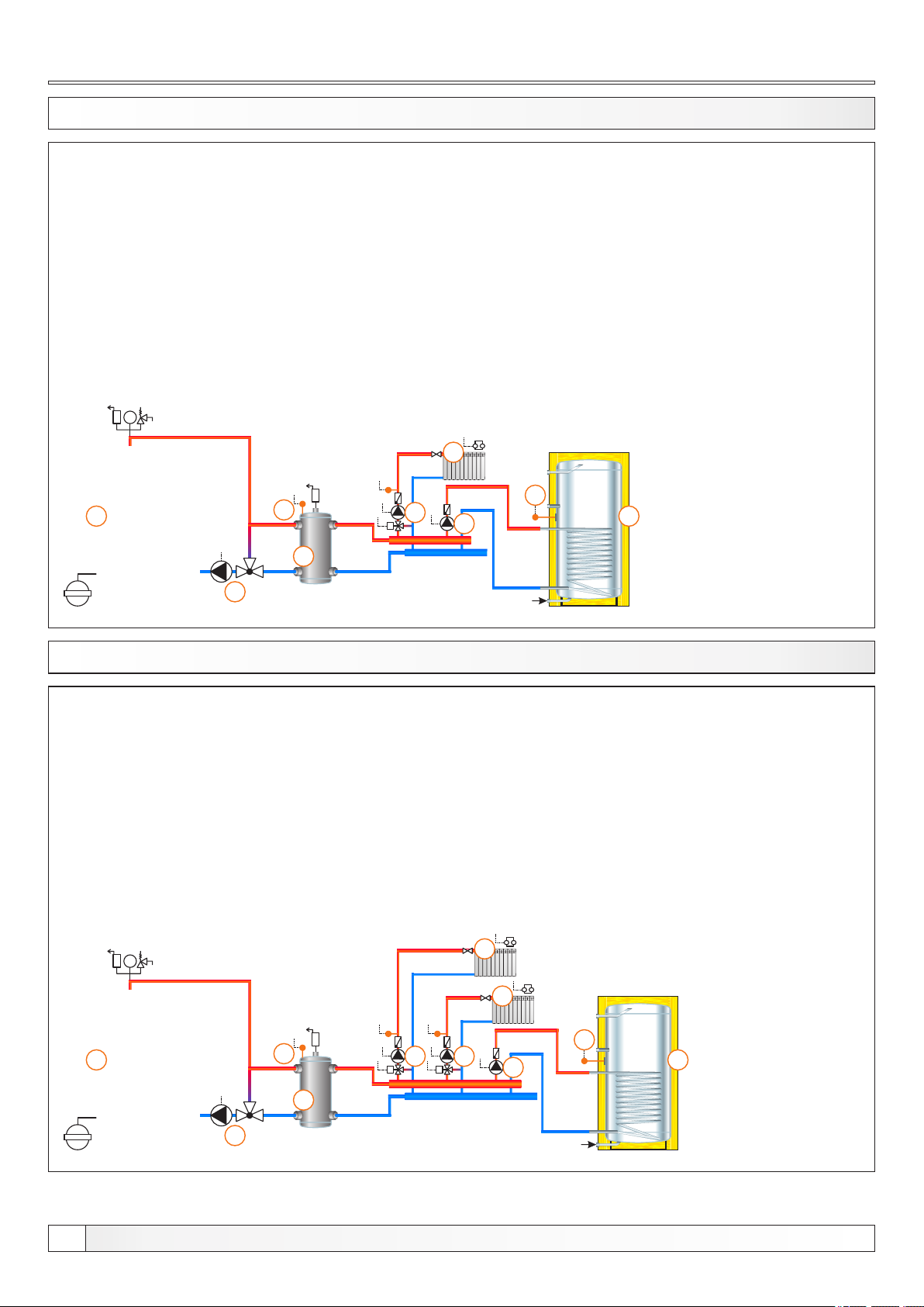
13.55. CONFIGURATION E-1-1
bar
1
4
2
1 - Boiler EKO-CK P + Cm Pelet-set
2 - Hydraulic crossover (CRO)
3 - 3-way themostatic mixing valve + pump (P1)
(return flow protection)
4 - CRO temp. sensor (BUFFER1)
5 - Mixing heating circuit
6 - DHW tank
7 - 1. circuit flow sensor (CIRCUIT1) + pump (P4) + actuator (MVAL1)
8 - DHW tank pump (P2)
9 - DHW tank sensor (DHW)
Temperatures:
Boiler temp.: 80°C (70-90°C)
CRO temp.: 75°C (65-80°C)
Tdhw: 50°C (10-70°C)
dTdhw: 5°C (3-20°C)
5
9
7
M
8
6
EKO-CK P
3
13.56. CONFIGURATION E-1-2
bar
1
4
1 - Boiler EKO-CK P + Cm Pelet-set
2 - Hydraulic crossover (CRO)
3 - 3-way themostatic mixing valve + pump (P1)
(return flow protection)
4 - CRO temp. sensor (BUFFER1)
5 - Mixing heating circuit (2x)
6 - DHW tank
7 - 1. circuit flow sensor (CIRCUIT1) + pump (P4) + actuator (MVAL1)
8 - 2. circuit flow sensor (CIRCUIT2) + pump (P5) + actuator (MVAL2)
9 - DHW tank pump (P2)
10 - DHW tank sensor (DHW)
Temperatures:
Boiler temp.: 80°C (70-90°C)
CRO temp.: 75°C (65-80°C)
Tdhw: 50°C (10-70°C)
dTdhw: 5°C (3-20°C)
5
5
10
8
7
MM
9
6
EKO-CK P
48
2
3
Technical instructions REGULATION Cm Pelet-set
Page 49
Configurations
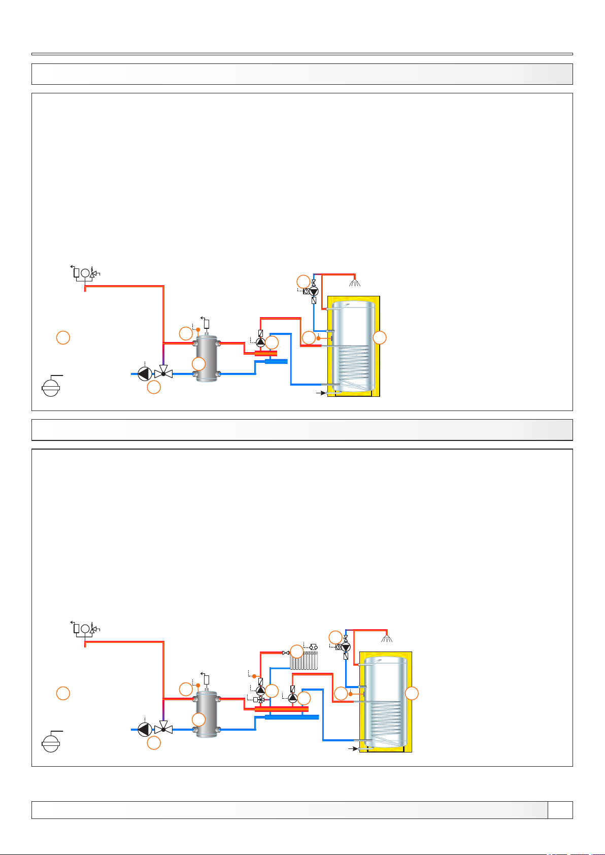
13.57. CONFIGURATION E-2-0
bar
1
4
2
1 - Boiler EKO-CK P + Cm Pelet-set
2 - Hydraulic crossover (CRO)
3 - 3-way themostatic mixing valve + pump (P1)
(return flow protection)
4 - CRO temp. sensor (BUFFER1)
5 - DHW tank
6 - DHW recirculation (P3)
7 - DHW tank pump (P2)
8 - DHW tank sensor (DHW)
Temperatures:
Boiler temp.: 80°C (70-90°C)
CRO temp.: 75°C (65-80°C)
Tdhw: 50°C (10-70°C)
dTdhw: 5°C (3-20°C)
6
7
8
5
EKO-CK P
3
13.58. CONFIGURATION E-2-1
bar
1 - Boiler EKO-CK P + Cm Pelet-set
2 - Hydraulic crossover (CRO)
3 - 3-way themostatic mixing valve + pump (P1)
(return flow protection)
4 - CRO temp. sensor (BUFFER1)
5 - Mixing heating circuit
6 - DHW tank
7 - DHW recirculation (P3)
8 - 1. circuit flow sensor (CIRCUIT1) + pump (P4) + actuator (MVAL1)
9 - DHW tank pump (P2)
10 - DHW tank sensor (DHW)
Temperatures:
Boiler temp.: 80°C (70-90°C)
CRO temp.: 75°C (65-80°C)
Tdhw: 50°C (10-70°C)
dTdhw: 5°C (3-20°C)
7
5
EKO-CK P
1
4
8
M
2
3
Technical instructions REGULATION Cm Pelet-set
9
10
6
49
Page 50
Configurations
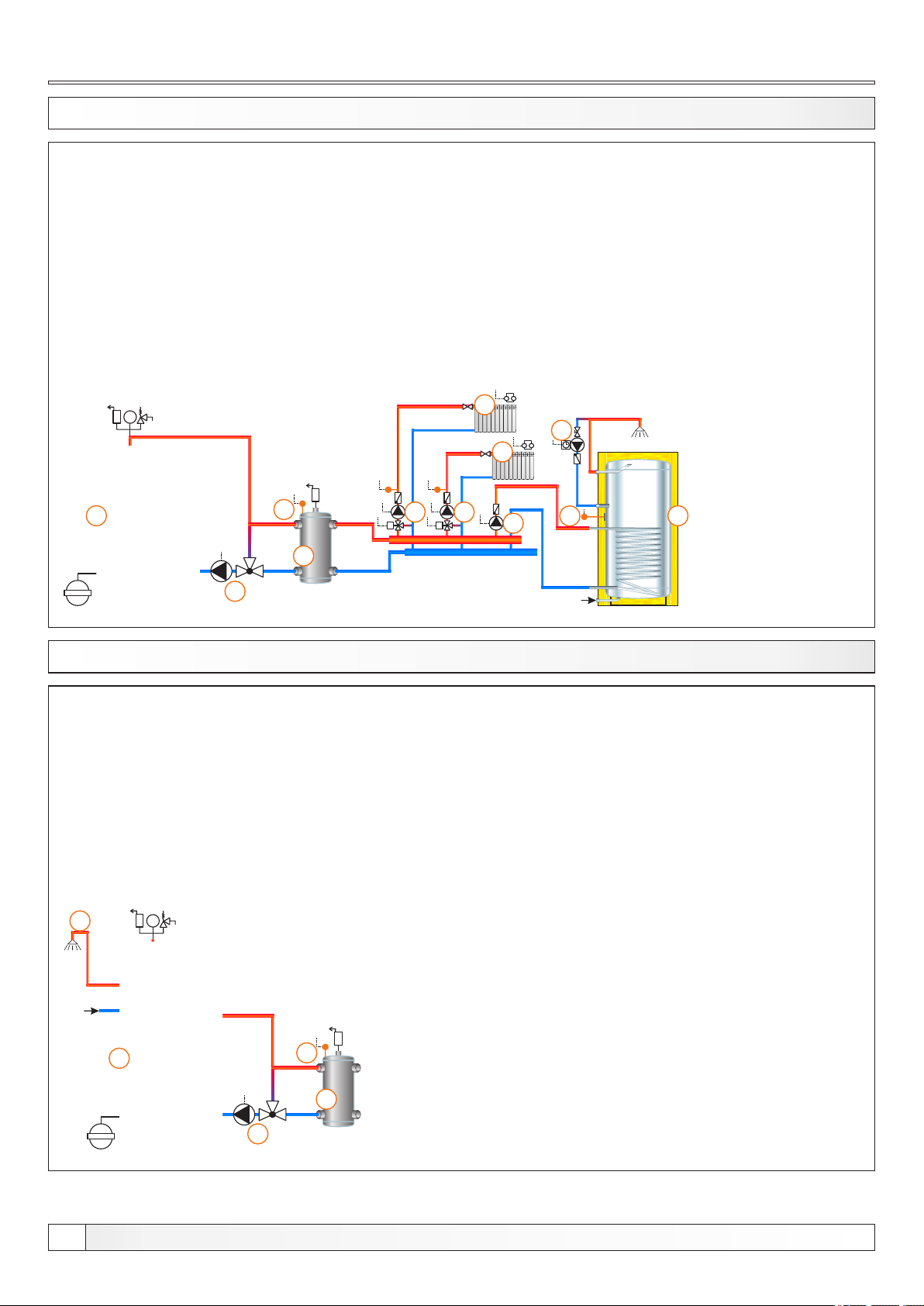
13.59. CONFIGURATION E-2-2
bar
1
4
2
1 - Boiler EKO-CK P + Cm Pelet-set
2 - Hydraulic crossover (CRO)
3 - 3-way themostatic mixing valve + pump (P1)
(return flow protection)
4 - CRO temp. sensor (BUFFER1)
5 - Mixing heating circuit (2x)
6 - DHW tank
7 - DHW recirculation (P3)
8 - 1. circuit flow sensor (CIRCUIT1) + pump (P4) + actuator (MVAL1)
9 - 2. circuit flow sensor (CIRCUIT2) + pump (P5) + actuator (MVAL2)
10 - DHW tank pump (P2)
11 - DHW tank sensor (DHW)
Temperatures:
Boiler temp.: 80°C (70-90°C)
CRO temp.: 75°C (65-80°C)
Tdhw: 50°C (10-70°C)
dTdhw: 5°C (3-20°C)
5
7
5
8
9
MM
10
11
6
EKO-CK P
3
13.60. CONFIGURATION E-7-0
5
bar
1 - Boiler EKO-CKB P + Cm Pelet-set
2 - Hydraulic crossover (CRO)
3 - 3-way themostatic mixing valve + pump (P1)
(return flow protection)
4 - CRO temp. sensor (BUFFER1)
5 - DHW tank in the boiler
Temperatures:
Boiler temp.: 80°C (70-90°C) = Tdhw
CRO temp.: 75°C (65-80°C)
EKO-CKB P
50
1
4
2
3
Technical instructions REGULATION Cm Pelet-set
Page 51
Configurations
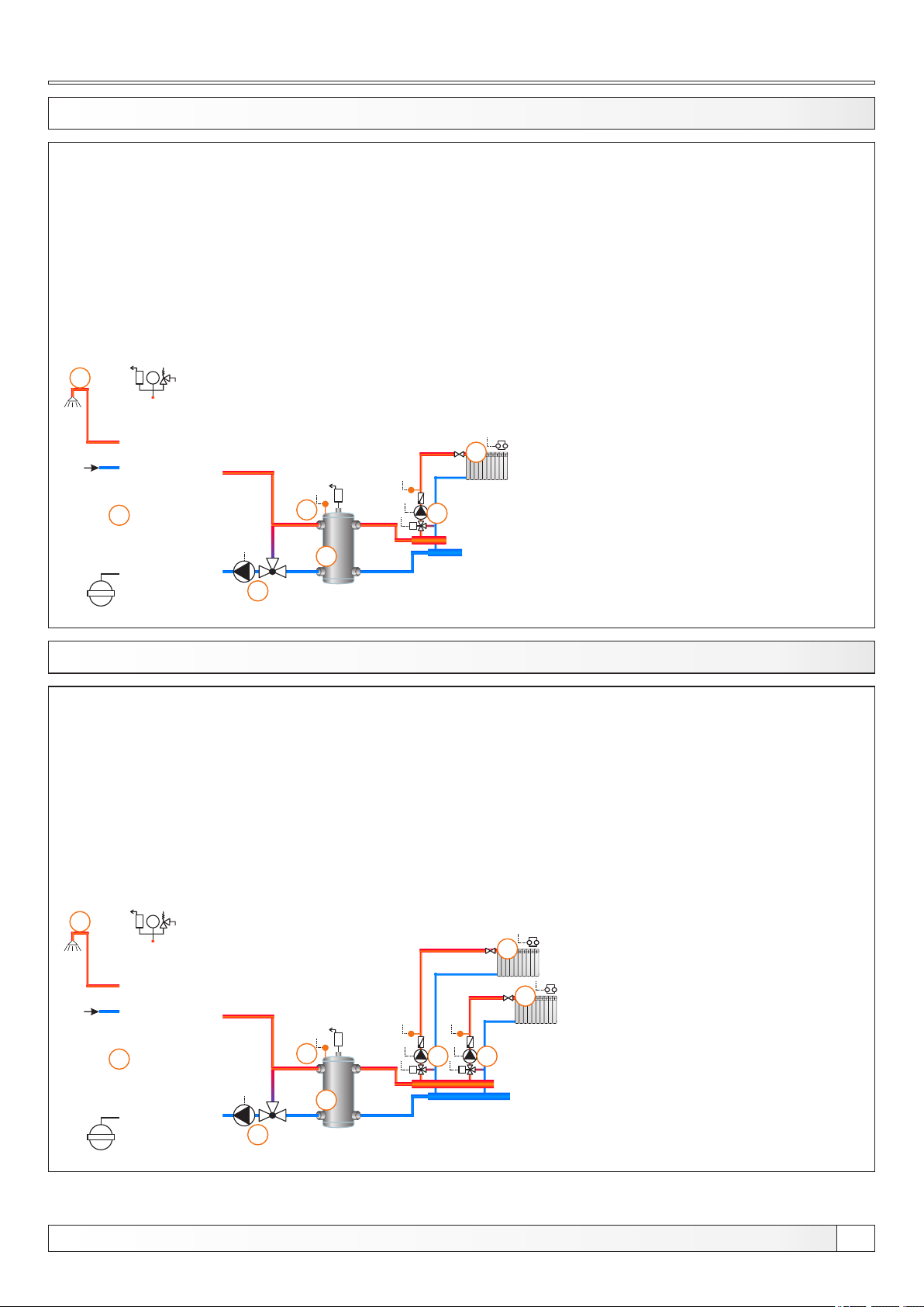
13.61. CONFIGURATION E-7-1
7
bar
1
4
2
1 - Boiler EKO-CKB P + Cm Pelet-set
2 - Hydraulic crossover (CRO)
3 - 3-way themostatic mixing valve + pump (P1)
(return flow protection)
4 - CRO temp. sensor (BUFFER1)
5 - Mixing heating circuit
6 - 1. circuit flow sensor (CIRCUIT1) + pump (P4) + actuator (MVAL1)
7 - DHW tank in the boiler
Temperatures:
Boiler temp.: 80°C (70-90°C) = Tdhw
CRO temp.: 75°C (65-80°C)
5
6
M
EKO-CKB P
3
13.62. CONFIGURATION E-7-2
8
bar
1 - Boiler EKO-CKB P + Cm Pelet-set
2 - Hydraulic crossover (CRO)
3 - 3-way themostatic mixing valve + pump (P1)
(return flow protection)
4 - CRO temp. sensor (BUFFER1)
5 - Mixing heating circuit
6 - 1. circuit flow sensor (CIRCUIT1) + pump (P4) + actuator (MVAL1)
7 - 2. circuit flow sensor (CIRCUIT2) + pump (P5) + actuator (MVAL2)
8 - DHW tank in the boiler
Temperatures:
Boiler temp.: 80°C (70-90°C) = Tdhw
CRO temp.: 75°C (65-80°C)
5
5
EKO-CKB P
1
4
7 6
2
3
Technical instructions REGULATION Cm Pelet-set
MM
51
Page 52
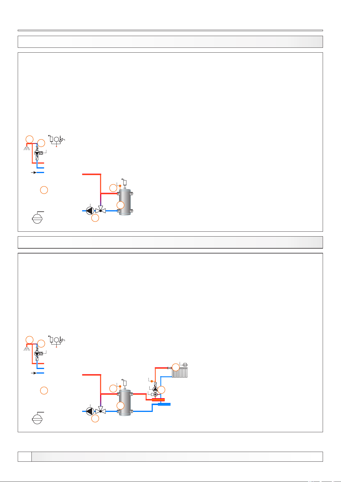
Configurations
13.63. CONFIGURATION E-8-0
5
bar
6
1
4
2
1 - Boiler EKO-CKB P + Cm Pelet-set
2 - Hydraulic crossover (CRO)
3 - 3-way themostatic mixing valve + pump (P1)
(return flow protection)
4 - CRO temp. sensor (BUFFER1)
5 - DHW tank in the boiler
6 - DHW tank recirculation (P3)
Temperatures:
Boiler temp.: 80°C (70-90°C) = Tdhw
CRO temp.: 75°C (65-80°C)
EKO-CKB P
3
13.64. CONFIGURATION E-8-1
7
bar
8
1 - Boiler EKO-CKB P + Cm Pelet-set
2 - Hydraulic crossover (CRO)
3 - 3-way themostatic mixing valve + pump (P1)
(return flow protection)
4 - CRO temp. sensor (BUFFER1)
5 - Mixing heating circuit
6 - 1. circuit flow sensor (CIRCUIT1) + pump (P4) + actuator (MVAL1)
7 - DHW tank in the boiler
8 - DHW recirculation (P3)
Temperatures:
Boiler temp.: 80°C (70-90°C) = Tdhw
CRO temp.: 75°C (65-80°C)
5
EKO-CKB P
52
1
4
6
M
2
3
Technical instructions REGULATION Cm Pelet-set
Page 53

Configurations
13.65. CONFIGURATION E-8-2
8
bar
9
1
4
2
1 - Boiler EKO-CKB P + Cm Pelet-set
2 - Hydraulic crossover (CRO)
3 - 3-way themostatic mixing valve + pump (P1)
(return flow protection)
4 - CRO temp. sensor (BUFFER1)
5 - Mixing heating circuit
6 - 1. circuit flow sensor (CIRCUIT1) + pump (P4) + actuator (MVAL1)
7 - 2. circuit flow sensor (CIRCUIT2) + pump (P5) + actuator (MVAL2)
8 - DHW tank in the boiler
9 - DHW tank recirculation (P3)
Temperatures:
Boiler temp.: 80°C (70-90°C) = Tdhw
CRO temp.: 75°C (65-80°C)
5
5
7 6
MM
EKO-CKB P
3
13.66. CONFIGURATION F-0-0
bar
EKO-CK P
1 - Boiler EKO-CK P + Cm Pelet-set
2 - Hydraulic crossover (CRO)
3 - 3-way mixing valve + actuator (MVAL2) + return flow temp. sensor (CIRCUIT2) + pump (P1)
(return flow protection)
4 - CRO temp. sensor (BUFFER1)
Temperatures:
Boiler temp.: 80°C (70-90°C)
CRO temp.: 75°C (65-80°C)
1
4
2
M
3
Technical instructions REGULATION Cm Pelet-set
53
Page 54
Configurations
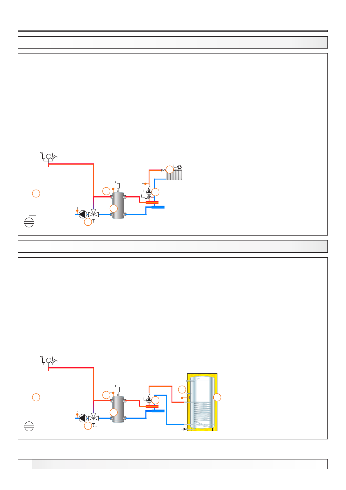
13.67. CONFIGURATION F-0-1
bar
1
3
4
2
M
1 - Boiler EKO-CK P + Cm Pelet-set
2 - Hydraulic crossover (CRO)
3 - 3-way mixing valve + actuator (MVAL2) + return flow temp. sensor (CIRCUIT2) + pump (P1)
(return flow protection)
4 - CRO temp. sensor (BUFFER1)
5 - Mixing heating circuit
6 - 1. circuit flow sensor (CIRCUIT1) + pump (P4) + actuator (MVAL1)
Temperatures:
Boiler temp.: 80°C (70-90°C)
CRO temp.: 75°C (65-80°C)
5
6
M
EKO-CK P
13.68. CONFIGURATION F-1-0
bar
1
3
4
2
M
EKO-CK P
1 - Boiler EKO-CK P + Cm Pelet-set
2 - Hydraulic crossover (CRO)
3 - 3-way mixing valve + actuator (MVAL2) + return flow temp. sensor (CIRCUIT2) + pump (P1)
(return flow protection)
4 - CRO temp. sensor (BUFFER1)
5 - DHW tank
6 - DHW tank pump (P2)
7 - DHW tank sensor (DHW)
Temperatures:
Boiler temp.: 80°C (70-90°C)
CRO temp.: 75°C (65-80°C)
Tdhw: 50°C (10-70°C)
dTdhw: 5°C (3-20°C)
7
6
5
54
Technical instructions REGULATION Cm Pelet-set
Page 55
Configurations
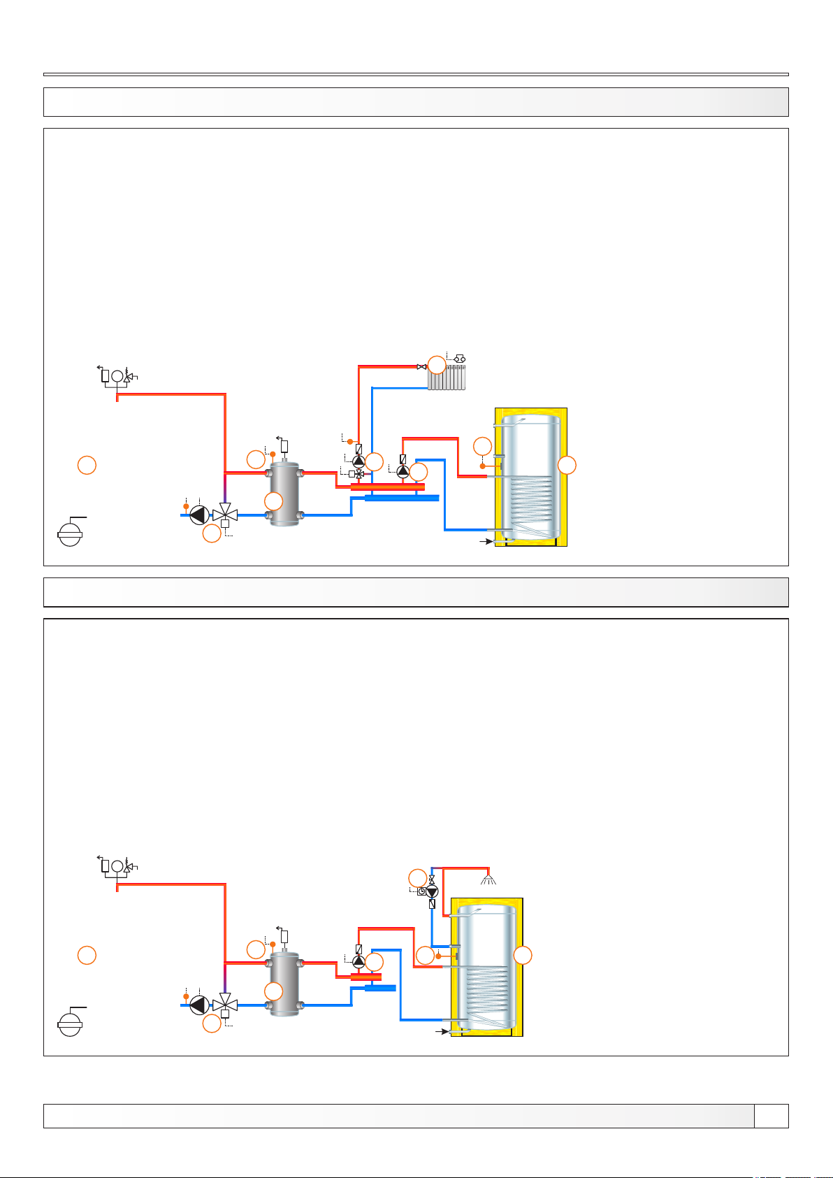
13.69. CONFIGURATION F-1-1
bar
1
3
4
2
M
1 - Boiler EKO-CK P + Cm Pelet-set
2 - Hydraulic crossover (CRO)
3 - 3-way mixing valve + actuator (MVAL2) + return flow temp. sensor (CIRCUIT2) + pump (P1)
(return flow protection)
4 - CRO temp. sensor (BUFFER1)
5 - Mixing heating circuit
6 - DHW tank
7 - 1. circuit flow sensor (CIRCUIT1) + pump (P4) + actuator (MVAL1)
8 - DHW tank pump (P2)
9 - DHW tank sensor (DHW)
Temperatures:
Boiler temp.: 80°C (70-90°C)
CRO temp.: 75°C (65-80°C)
Tdhw: 50°C (10-70°C)
dTdhw: 5°C (3-20°C)
5
9
7
M
8
6
EKO-CK P
13.70. CONFIGURATION F-2-0
bar
1
3
4
2
M
EKO-CK P
1 - Boiler EKO-CK P + Cm Pelet-set
2 - Hydraulic crossover (CRO)
3 - 3-way mixing valve + actuator (MVAL2) + return flow temp. sensor (CIRCUIT2) + pump (P1)
(return flow protection)
4 - CRO temp. sensor (BUFFER1)
5 - DHW tank
6 - DHW recirculation (P3)
7 - DHW tank pump (P2)
8 - DHW tank sensor (DHW)
Temperatures:
Boiler temp.: 80°C (70-90°C)
CRO temp.: 75°C (65-80°C)
Tdhw: 50°C (10-70°C)
dTdhw: 5°C (3-20°C)
6
7
8
5
Technical instructions REGULATION Cm Pelet-set
55
Page 56
Configurations
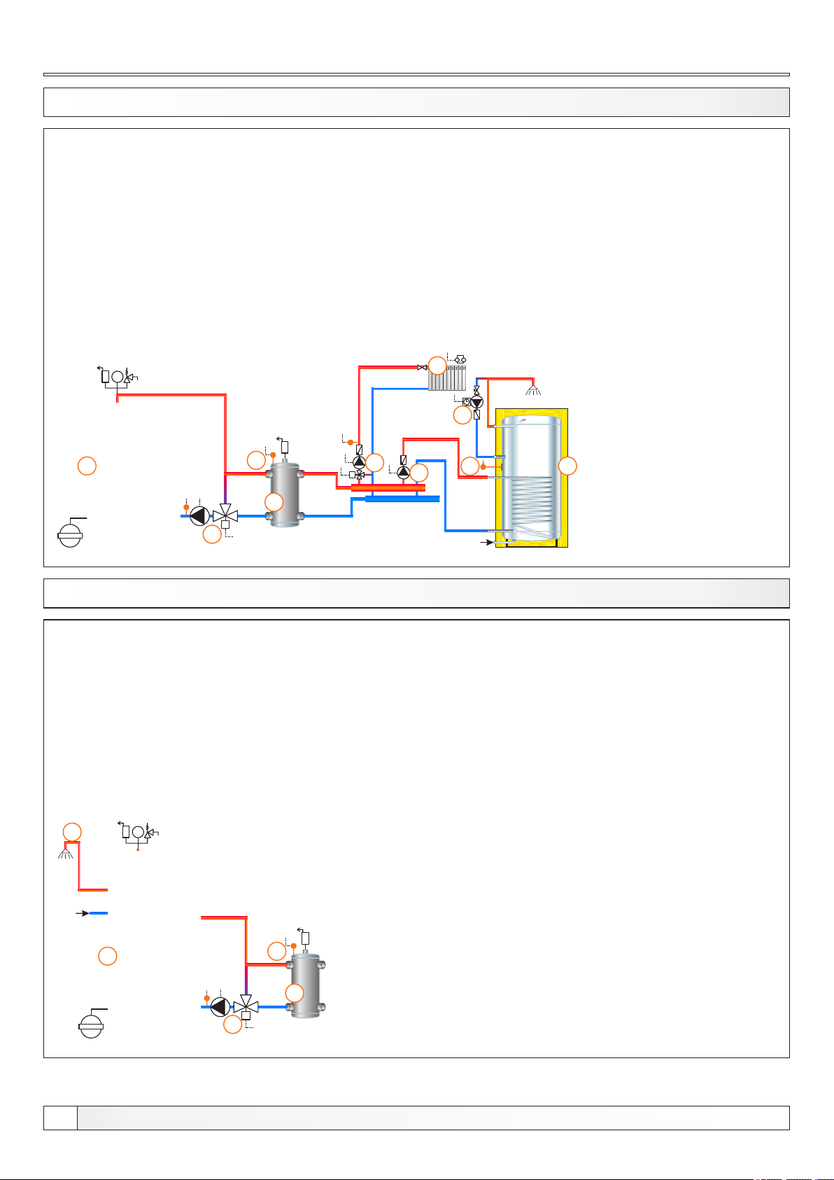
13.71. KONFIGURACIJA F-2-1
bar
1
3
4
2
M
1 - Boiler EKO-CK P + Cm Pelet-set
2 - Hydraulic crossover (CRO)
3 - 3-way mixing valve + actuator (MVAL2) + return flow temp. sensor (CIRCUIT2) + pump (P1)
(return flow protection)
4 - CRO temp. sensor (BUFFER1)
5 - Mixing heating circuit
6 - DHW tank
7 - DHW recirculation (P3)
8 - 1. circuit flow sensor (CIRCUIT1) + pump (P4) + actuator (MVAL1)
9 - DHW tank pump (P2)
10 - DHW tank sensor (DHW)
Temperatures:
Boiler temp.: 80°C (70-90°C)
CRO temp.: 75°C (65-80°C)
Tdhw: 50°C (10-70°C)
dTdhw: 5°C (3-20°C)
5
7
8
M
9
10
6
EKO-CK P
13.72. KONFIGURACIJA F-7-0
5
bar
1
4
2
M
3
EKO-CKB P
1 - Boiler EKO-CKB P + Cm Pelet-set
2 - Hydraulic crossover (CRO)
3 - 3-way mixing valve + actuator (MVAL2) + return flow temp. sensor (CIRCUIT2) + pump (P1)
(return flow protection)
4 - CRO temp. sensor (BUFFER1)
5 - DHW tank in the boiler
Temperatures:
Boiler temp.: 80°C (70-90°C) = Tdhw
CRO temp.: 75°C (65-80°C)
56
Technical instructions REGULATION Cm Pelet-set
Page 57
Configurations
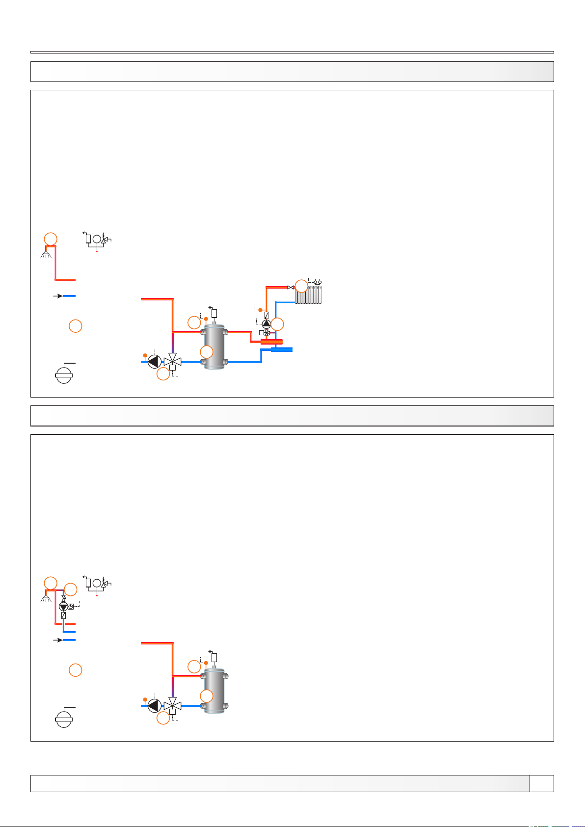
13.73. CONFIGURATION F-7-1
7
bar
1
4
2
M
3
EKO-CKB P
1 - Boiler EKO-CKB P + Cm Pelet-set
2 - Hydraulic crossover (CRO)
3 - 3-way mixing valve + actuator (MVAL2) + return flow temp. sensor (CIRCUIT2) + pump (P1)
(return flow protection)
4 - CRO temp. sensor (BUFFER1)
5 - Mixing heating circuit
6 - 1. circuit flow sensor (CIRCUIT1) + pump (P4) + actuator (MVAL1)
7 - DHW tank in the boiler
Temperatures:
Boiler temp.: 80°C (70-90°C) = Tdhw
CRO temp.: 75°C (65-80°C)
5
6
M
13.74. CONFIGURATION F-8-0
5
bar
6
1
4
2
M
3
EKO-CKB P
1 - Boiler EKO-CKB P + Cm Pelet-set
2 - Hydraulic crossover (CRO)
3 - 3-way mixing valve + actuator (MVAL2) + return flow temp. sensor (CIRCUIT2) + pump (P1)
(return flow protection)
4 - CRO temp. sensor (BUFFER1)
5 - DHW tank in the boiler
6 - DHW tank recirculation (P3)
Temperatures:
Boiler temp.: 80°C (70-90°C) = Tdhw
CRO temp.: 75°C (65-80°C)
Technical instructions REGULATION Cm Pelet-set
57
Page 58
Configurations
13.75. CONFIGURATION F-8-1
7
bar
8
1
4
2
M
3
EKO-CKB P
1 - Boiler EKO-CKB P + Cm Pelet-set
2 - Hydraulic crossover (CRO)
3 - 3-way mixing valve + actuator (MVAL2) + return flow temp. sensor (CIRCUIT2) + pump (P1)
(return flow protection)
4 - CRO temp. sensor (BUFFER1)
5 - Mixing heating circuit
6 - 1. circuit flow sensor (CIRCUIT1) + pump (P4) + actuator (MVAL1)
7 - DHW tank in the boiler
8 - DHW tank recirculation (P3)
Temperatures:
Boiler temp.: 80°C (70-90°C) = Tdhw
CRO temp.: 75°C (65-80°C)
5
6
M
13.76. CONFIGURATION I-0-0
bar
4
1
M
3
5
1 - Boiler EKO-CK P + Cm Pelet-set
2 - Accumulation tank
3 - 4-way mixing valve + actuator (MVAL2) + return flow temp. sensor (CIRCUIT2) + pump (P1)
(return flow protection)
4 - Accumulation tank upper temp. sensor (BUFFER1)
5 - Accumulation tank lower temp. sensor (BUFFER2)
Temperatures:
Boiler temp.: 80°C (80-90°C)
Tpuf: 80°C (65-80°C)
dTpuf: 10°C (5-30°C)
dTbuf-off: 5°C (3-50°C )
2
EKO-CK P
58
Technical instructions REGULATION Cm Pelet-set
Page 59
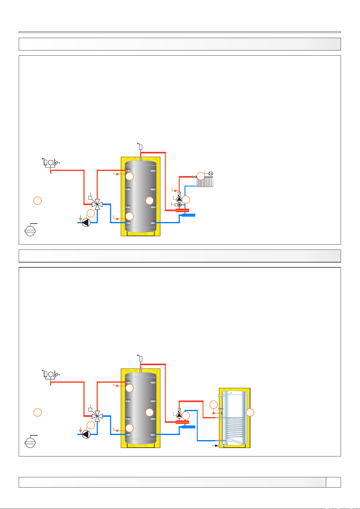
Configurations
13.77. CONFIGURATION I-0-1 EKO-CK P
1 - Boiler EKO-CK P + Cm Pelet-set
2 - Accumulation tank
3 - 4-way mixing valve + actuator (MVAL2) + return flow temp. sensor (CIRCUIT2) + pump (P1)
(return flow protection)
4 - Accumulation tank upper temp. sensor (BUFFER1)
5 - Accumulation tank lower temp. sensor (BUFFER2)
6 - Mixing heating circuit
7 - 1. circuit flow sensor (CIRCUIT1) + pump (P4) + actuator (MVAL1)
Temperatures:
Boiler temp.: 80°C (80-90°C)
Tpuf: 80°C (65-80°C)
dTpuf: 10°C (5-30°C)
dTbuf-off: 5°C (3-50°C )
Tbuf min.: 20°C (5-85°C)
bar
4
1
M
3
5
13.78. CONFIGURATION I-1-0
6
2
1 - Boiler EKO-CK P + Cm Pelet-set
2 - Accumulation tank
3 - 4-way mixing valve + actuator (MVAL2) + return flow temp. sensor (CIRCUIT2) + pump (P1)
(return flow protection)
4 - Accumulation tank upper temp. sensor (BUFFER1)
5 - Accumulation tank lower temp. sensor (BUFFER2)
6 - DHW tank
7 - DHW tank pump (P2)
8 - DHW tank sensor (DHW)
Temperatures:
Boiler temp.: 80°C (80-90°C)
Tpuf: 80°C (65-80°C)
dTpuf: 10°C (5-30°C)
dTbuf-off: 5°C (3-50°C )
Tdhw: 50°C (10-70°C)
dTdhw: 5°C (3-20°C)
7
M
EKO-CK P
bar
4
1
M
3
5
2
Technical instructions REGULATION Cm Pelet-set
8
7
6
59
Page 60
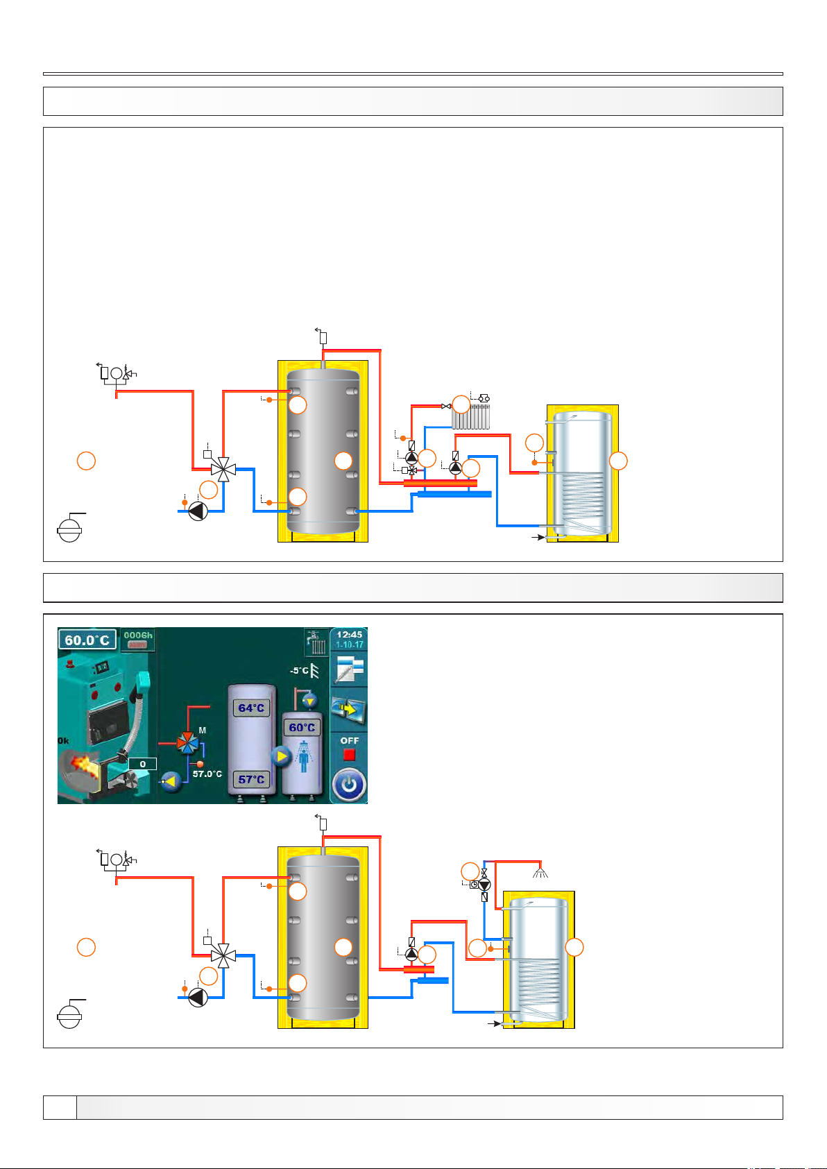
Configurations
13.79. CONFIGURATION I-1-1
bar
4
1
M
3
5
1 - Boiler EKO-CK P + Cm Pelet-set
2 - Accumulation tank
3 - 4-way mixing valve + actuator (MVAL2) + return flow temp. sensor (CIRCUIT2) + pump (P1)
(return flow protection)
4 - Accumulation tank upper temp. sensor (BUFFER1)
5 - Accumulation tank lower temp. sensor (BUFFER2)
6 - Mixing heating circuit
7 - DHW tank
8 - 1. circuit flow sensor (CIRCUIT1) + pump (P4) + actuator (MVAL1)
9 - DHW tank pump (P2)
10 - DHW tank sensor (DHW)
Temperatures:
Boiler temp.: 80°C (80-90°C)
Tpuf: 80°C (65-80°C)
dTpuf: 10°C (5-30°C)
dTbuf-off: 5°C (3-50°C )
Tdhw: 50°C (10-70°C)
dTdhw: 5°C (3-20°C)
dTbuf min.: 20°C (5-85°C)
6
10
2
8
M
9
7
EKO-CK P
13.80. CONFIGURATION I-2-0
bar
4
1
M
3
5
1 - Boiler EKO-CK P + Cm Pelet-set
2 - Accumulation tank
3 - 4-way mixing + with actuator (MVAL2) + return flow temp. sensor (CIRCUIT2) + pump (P1)
(return flow protection)
4 - Accumulation tank upper temp. sensor (BUFFER1)
5 - Accumulation tank lower temp. sensor (BUFFER2)
6 - DHW tank
7 - DHW recirculation (P3)
8 - DHW tank pump (P2)
9 - DHW tank sensor (DHW)
Temperatures:
Boiler temp.: 80°C (80-90°C)
Tpuf: 80°C (65-80°C)
dTpuf: 10°C (5-30°C)
dTbuf-off: 5°C (3-50°C )
Tdhw: 50°C (10-70°C)
dTdhw: 5°C (3-20°C)
7
2
8
9
6
EKO-CK P
60
Technical instructions REGULATION Cm Pelet-set
Page 61
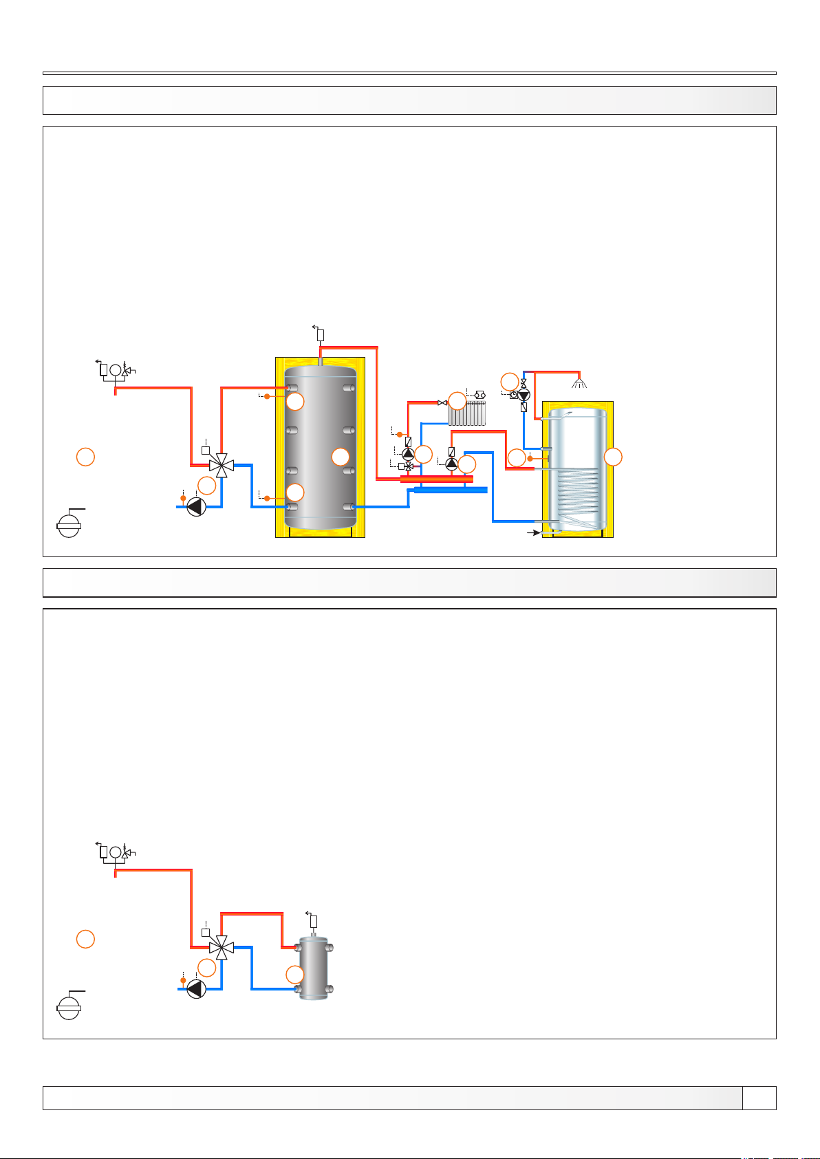
Configurations
13.81. CONFIGURATION I-2-1
bar
4
1
M
3
5
1 - Boiler EKO-CK P + Cm Pelet-set
2 - Accumulation tank
3 - 4-way mixing valve + actuator (MVAL2) + return flow temp. sensor (CIRCUIT2) + pump (P1)
(return flow protection)
4 - Accumulation tank upper temp. sensor (BUFFER1)
5 - Accumulation tank lower temp. sensor (BUFFER2)
6 - Mixing heating circuit
7 - DHW tank
8 - DHW recirculation (P3)
9 - 1. circuit flow sensor (CIRCUIT1) + pump (P4) + actuator (MVAL1)
10 - DHW tank pump (P2)
11 - DHW tank sensor (DHW)
Temperatures:
Boiler temp.: 80°C (80-90°C)
Tpuf: 80°C (65-80°C)
dTpuf: 10°C (5-30°C)
dTbuf-off: 5°C (3-50°C )
Tdhw: 50°C (10-70°C)
dTdhw: 5°C (3-20°C)
Tbuf min.: 20°C (5-85°C)
8
6
2
9
M
10
11
7
EKO-CK P
13.82. CONFIGURATION J-0-0
bar
1
M
3
2
EKO-CK P
1 - Boiler EKO-CK P + Cm Pelet-set
2 - Hydraulic crossover (CRO)
3 - 4-way mixing valve + actuator (MVAL2) + return flow temp. sensor (CIRCUIT2) + pump (P1)
(return flow protection)
Temperatures:
Boiler temp.: 80°C (70-90°C)
Technical instructions REGULATION Cm Pelet-set
61
Page 62
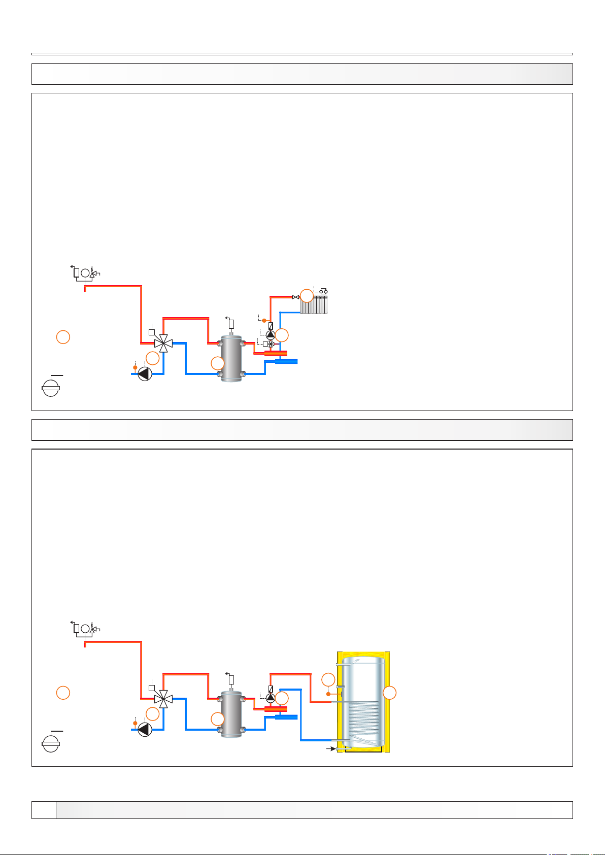
Configurations
13.83. CONFIGURATION J-0-1
bar
1
M
3
2
EKO-CK P
1 - Boiler EKO-CK P + Cm Pelet-set
2 - Hydraulic crossover (CRO)
3 - 4-way mixing valve + actuator (MVAL2) + return flow temp. sensor (CIRCUIT2) + pump (P1)
(return flow protection)
4 - Mixing heating circuit
5 - 1. circuit flow sensor (CIRCUIT1) + pump (P4) + actuator (MVAL1)
Temperatures:
Boiler temp.: 80°C (70-90°C)
4
5
M
13.84. CONFIGURATION J-1-0
bar
1
M
3
2
EKO-CK P
1 - Boiler EKO-CK P + Cm Pelet-set
2 - Hydraulic crossover (CRO)
3 - 4-way mixing valve + actuator (MVAL2) + return flow temp. sensor (CIRCUIT2) + pump (P1)
(return flow protection)
4 - DHW tank
5 - DHW tank pump (P2)
6 - DHW tank sensor (DHW)
Temperatures:
Boiler temp.: 80°C (70-90°C)
Tdhw: 50°C (10-70°C)
dTdhw: 5°C (3-20°C)
6
5
4
62
Technical instructions REGULATION Cm Pelet-set
Page 63
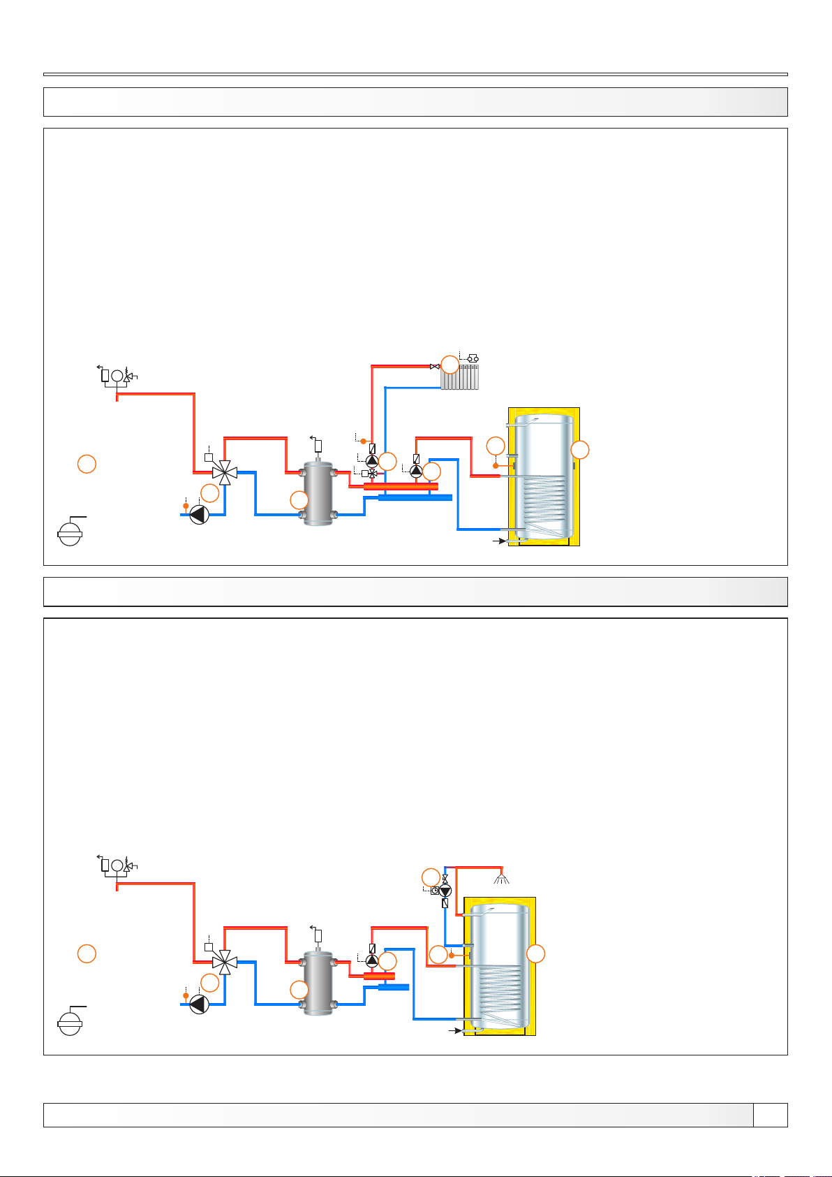
Configurations
13.85. CONFIGURATION J-1-1
bar
1
M
3
2
EKO-CK P
1 - Boiler EKO-CK P + Cm Pelet-set
2 - Hydraulic crossover (CRO)
3 - 4-way mixing valve + actuator (MVAL2) + return flow temp. sensor (CIRCUIT2) + pump (P1)
(return flow protection)
4 - Mixing heating circuit
5 - DHW tank
6 - 1. circuit flow sensor (CIRCUIT1) + pump (P4) + actuator (MVAL1)
7 - DHW tank pump (P2)
8 - DHW tank sensor (DHW)
Temperatures:
Boiler temp.: 80°C (70-90°C)
Tdhw: 50°C (10-70°C)
dTdhw: 5°C (3-20°C)
4
8
6
M
7
5
13.86. CONFIGURATION J-2-0
bar
1
M
3
2
EKO-CK P
1 - Boiler EKO-CK P + Cm Pelet-set
2 - Hydraulic crossover (CRO)
3 - 4-way mixing valve + actuator (MVAL2) + return flow temp. sensor (CIRCUIT2) + pump (P1)
(return flow protection)
4 - DHW tank
5 - DHW recirculation (P3)
6 - DHW tank pump (P2)
7 - DHW tank sensor (DHW)
Temperatures:
Boiler temp.: 80°C (70-90°C)
Tdhw: 50°C (10-70°C)
dTdhw: 5°C (3-20°C)
5
6
7
4
Technical instructions REGULATION Cm Pelet-set
63
Page 64
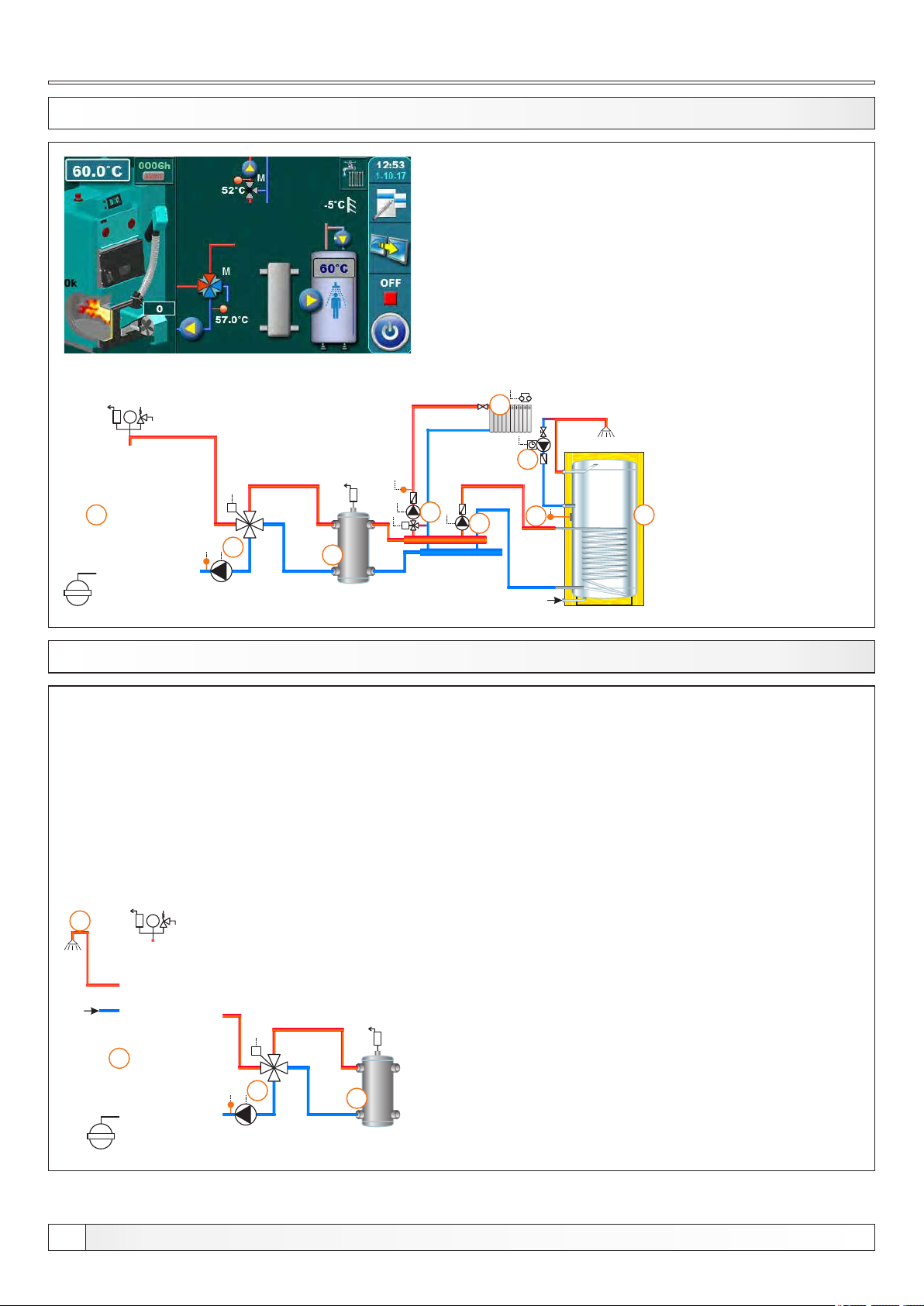
Configurations
13.87. CONFIGURATION J-2-1
bar
1
M
3
2
EKO-CK P
1 - Boiler EKO-CK P + Cm Pelet-set
2 - Hydraulic crossover (CRO)
3 - 4-way mixing valve + actuator (MVAL2) + return flow temp. sensor (CIRCUIT2) + pump (P1)
(return flow protection)
4 - Mixing heating circuit
5 - DHW tank
6 - DHW recirculation (P3)
7 - 1. circuit flow sensor (CIRCUIT1) + pump (P4) + actuator (MVAL1)
8 - DHW tank pump (P2)
9 - DHW tank sensor (DHW)
Temperatures:
Boiler temp.: 80°C (70-90°C)
Tdhw: 50°C (10-70°C)
dTdhw: 5°C (3-20°C)
4
6
7
M
8
9
5
13.88. CONFIGURATION J-7-0
4
bar
1
M
3
2
EKO-CKB P
1 - Boiler EKO-CKB P + Cm Pelet-set
2 - Hydraulic crossover (CRO)
3 - 4-way mixing valve + actuator (MVAL2) + return flow temp. sensor (CIRCUIT2) + pump (P1)
(return flow protection)
4 - DHW tank in the boiler
Temperatures:
Boiler temp.: 80°C (70-90°C) = Tdhw
64
Technical instructions REGULATION Cm Pelet-set
Page 65
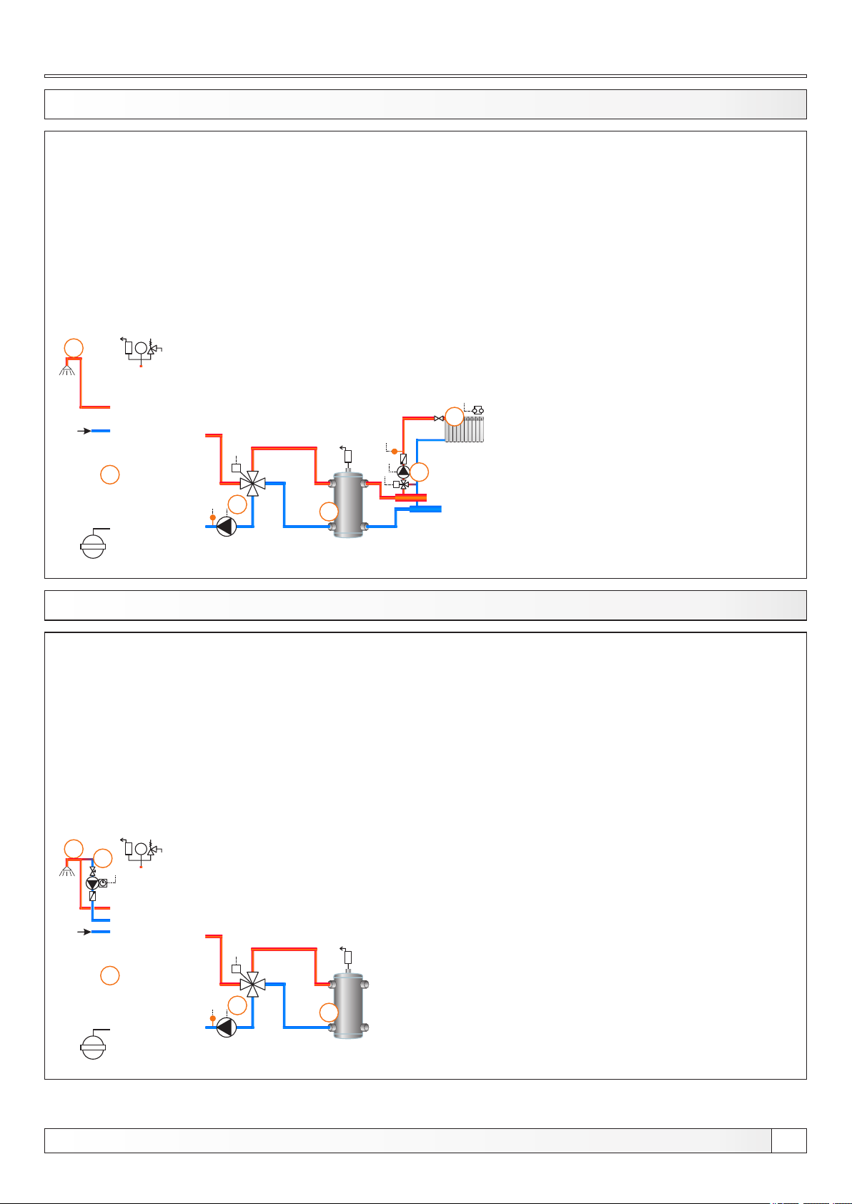
Configurations
13.89. CONFIGURATION J-7-1
6
bar
1
M
3
2
EKO-CKB P
1 - Boiler EKO-CKB P + Cm Pelet-set
2 - Hydraulic crossover (CRO)
3 - 4-way mixing valve + actuator (MVAL2) + return flow temp. sensor (CIRCUIT2) + pump (P1)
(return flow protection)
4 - Mixing heating circuit
5 - 1. circuit flow sensor (CIRCUIT1) + pump (P4) + actuator (MVAL1)
6 - DHW tank in the boiler
Temperatures:
Boiler temp.: 80°C (70-90°C) = Tdhw
4
5
M
13.90. KONFIGURACIJA J-8-0
13.90. CONFIGURATION J-8-0
4
bar
5
1
M
3
2
EKO-CKB P
1 - Boiler EKO-CKB P + Cm Pelet-set
2 - Hydraulic crossover (CRO)
3 - 4-way mixing valve + actuator (MVAL2) + return flow temp. sensor (CIRCUIT2) + pump (P1)
(return flow protection)
4 - DHW tank in the boiler
6 - DHW tank recirculation (P3)
Temperatures:
Boiler temp.: 80°C (70-90°C) = Tdhw
Technical instructions REGULATION Cm Pelet-set
65
Page 66
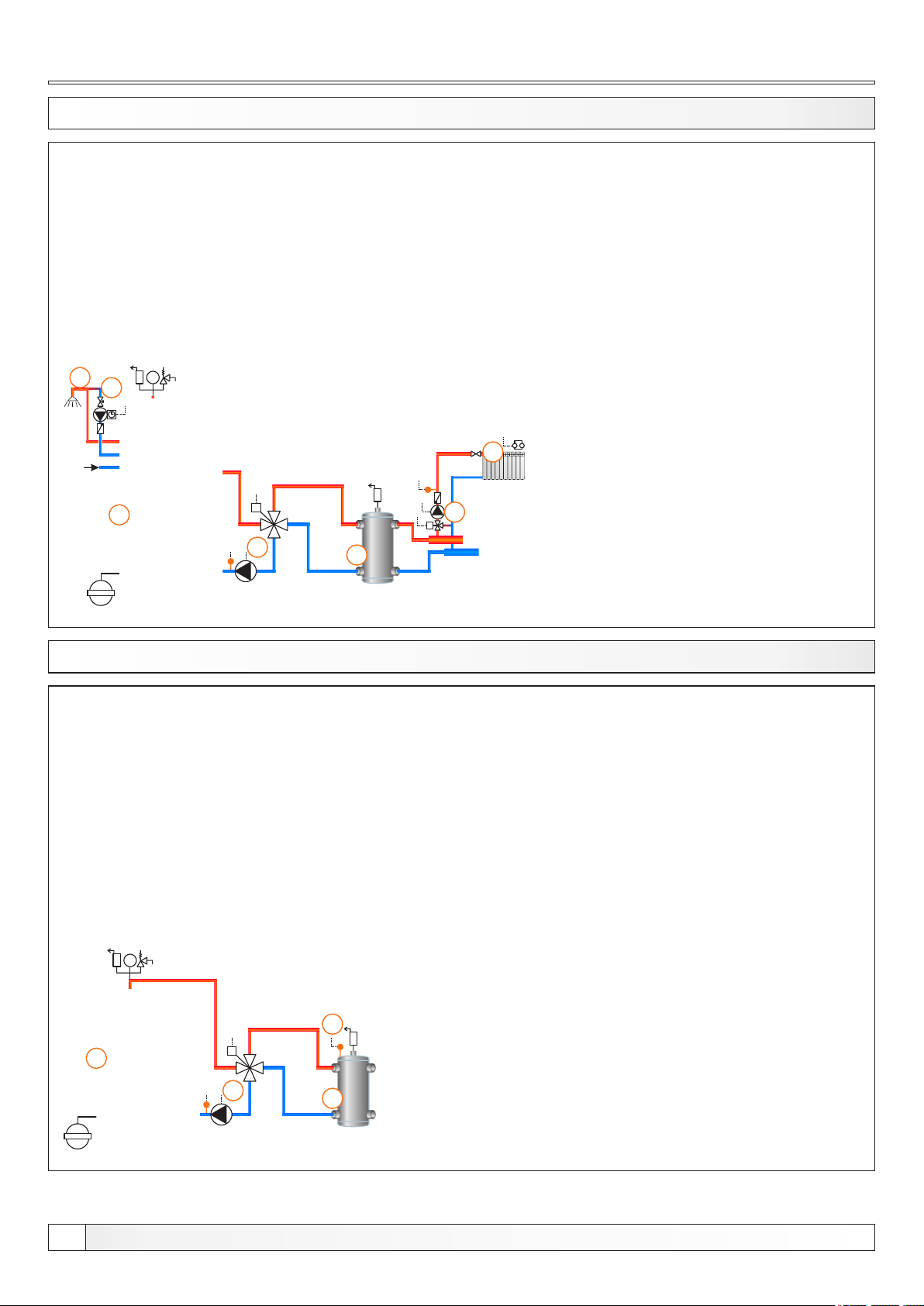
Configurations
13.91. CONFIGURATION J-8-1
6
bar
7
1
M
3
2
EKO-CKB P
1 - Boiler EKO-CKB P + Cm Pelet-set
2 - Hydraulic crossover (CRO)
3 - 4-way mixing valve + actuator (MVAL2) + return flow temp. sensor (CIRCUIT2) + pump (P1)
(return flow protection)
4 - Mixing heating circuit
5 - 1. circuit flow sensor (CIRCUIT1) + pump (P4) + actuator (MVAL1)
6 - DHW tank in the boiler
7 - DHW tank recirculation (P3)
Temperatures:
Boiler temp.: 80°C (70-90°C) = Tdhw
4
5
M
13.92. CONFIGURATION K-0-0
bar
4
1
M
3
2
EKO-CK P
1 - Boiler EKO-CK P + Cm Pelet-set
2 - Hydraulic crossover (CRO)
3 - 4-way mixing valve + actuator (MVAL2) + return flow temp. sensor (CIRCUIT2) + pump (P1)
(return flow protection)
4 - CRO temp. sensor (BUFFER1)
Temperatures:
Boiler temp.: 80°C (70-90°C)
CRO temp: 75°C (65-80°C)
66
Technical instructions REGULATION Cm Pelet-set
Page 67
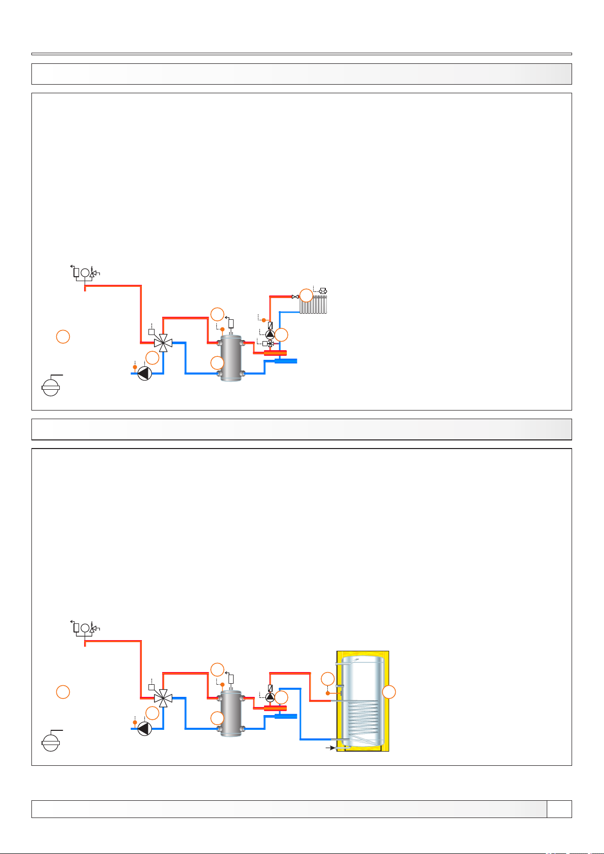
Configurations
13.93. CONFIGURATION K-0-1
bar
4
1
M
3
2
EKO-CK P
1 - Boiler EKO-CK P + Cm Pelet-set
2 - Hydraulic crossover (CRO)
3 - 4-way mixing valve + actuator (MVAL2) +return flow temp. sensor (CIRCUIT2) + pump (P1)
(return flow protection)
4 - CRO temp. sensor (BUFFER1)
5 - Mixing heating circuit
6 - 1. circuit flow sensor (CIRCUIT1) + pump (P4) + actuator (MVAL1)
Temperatures:
Boiler temp.: 80°C (70-90°C)
CRO temp: 75°C (65-80°C)
5
6
M
13.94. CONFIGURATION K-1-0
bar
4
1
M
3
2
EKO-CK P
1 - Boiler EKO-CK P + Cm Pelet-set
2 - Hydraulic crossover (CRO)
3 - 4-way mixing valve + actuator (MVAL2) + return flow temp. sensor (CIRCUIT2) + pump (P1)
(return flow protection)
4 - CRO temp. sensor (BUFFER1)
5 - DHW tank
6 - DHW tank pump (P2)
7 - DHW tank sensor (DHW)
Temperatures:
Boiler temp.: 80°C (70-90°C)
CRO temp: 75°C (65-80°C)
Tdhw: 50°C (10-70°C)
dTdhw: 5°C (3-20°C)
7
6
5
Technical instructions REGULATION Cm Pelet-set
67
Page 68
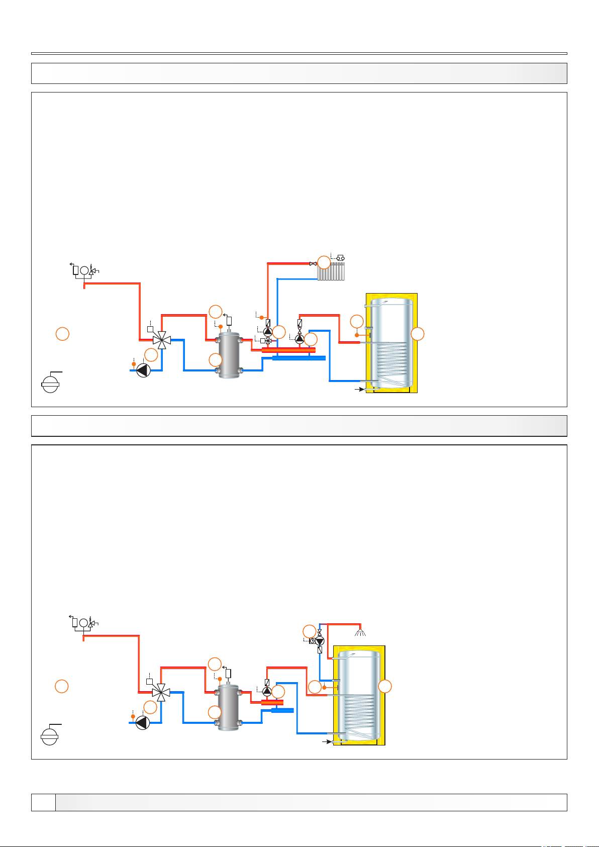
Configurations
13.95. CONFIGURATION K-1-1
bar
4
1
M
3
2
EKO-CK P
1 - Boiler EKO-CK P + Cm Pelet-set
2 - Hydraulic crossover (CRO)
3 - 4-way mixing valve + actuator (MVAL2) + return flow temp. sensor (CIRCUIT2) + pump (P1)
(return flow protection)
4 - CRO temp. sensor (BUFFER1)
5 - Mixing heating circuit
6 - DHW tank
7 - 1. circuit flow sensor (CIRCUIT1) + pump (P4) + actuator (MVAL1)
8 - DHW tank pump (P2)
9 - DHW tank sensor (DHW)
Temperatures:
Boiler temp.: 80°C (70-90°C)
CRO temp: 75°C (65-80°C)
Tdhw: 50°C (10-70°C)
dTdhw: 5°C (3-20°C)
5
9
7
M
8
6
13.96. CONFIGURATION K-2-0 EKO-CK P
1 - Boiler EKO-CK P + Cm Pelet-set
2 - Hydraulic crossover (CRO)
3 - 4-way mixing valve + actuator (MVAL2) + return flow temp. sensor (CIRCUIT2) + pump (P1)
(return flow protection)
4 - CRO temp. sensor (BUFFER1)
5 - DHW tank
6 - DHW recirculation (P3)
7 - DHW tank pump (P2)
8 - DHW tank sensor (DHW)
Temperatures:
Boiler temp.: 80°C (70-90°C)
CRO temp: 75°C (65-80°C)
Tdhw: 50°C (10-70°C)
dTdhw: 5°C (3-20°C)
bar
6
4
1
M
7
3
2
8
5
68
Technical instructions REGULATION Cm Pelet-set
Page 69
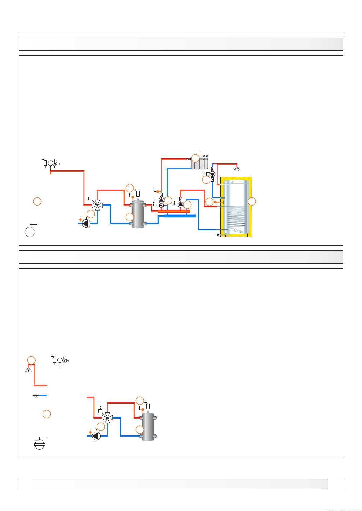
Configurations
13.97. CONFIGURATION K-2-1 EKO-CK P
1 - Boiler EKO-CK P + Cm Pelet-set
2 - Hydraulic crossover (CRO)
3 - 4-way mixing valve + actuator (MVAL2) + return flow temp. sensor (CIRCUIT2) + pump (P1)
(return flow protection)
4 - CRO temp. sensor (BUFFER1)
5 - Mixing heating circuit
6 - DHW tank
7 - DHW recirculation (P3)
8 - 1. circuit flow sensor ( CIRCUIT1) + pump (P4) + actuator (MVAL1)
9 - DHW tank pump (P2)
10 - DHW tank sensor (DHW)
Temperatures:
Boiler temp.: 80°C (70-90°C)
CRO temp: 75°C (65-80°C)
Tdhw: 50°C (10-70°C)
dTdhw: 5°C (3-20°C)
bar
4
1
M
3
2
13.98. CONFIGURATION K-7-0
5
7
8
M
9
10
6
EKO-CKB P
1 - Boiler EKO-CKB P + Cm Pelet-set
2 - Hydraulic crossover (CRO)
3 - 4-way mixing valve + actuator (MVAL2) + return flow temp. sensor (CIRCUIT2) + pump (P1)
(return flow protection)
4 - CRO temp. sensor (BUFFER1)
5 - DHW tank in the boiler
Temperatures:
Boiler temp.: 80°C (70-90°C) - Tdhw
CRO temp: 75°C (65-80°C)
5
bar
4
1
M
3
2
Technical instructions REGULATION Cm Pelet-set
69
Page 70
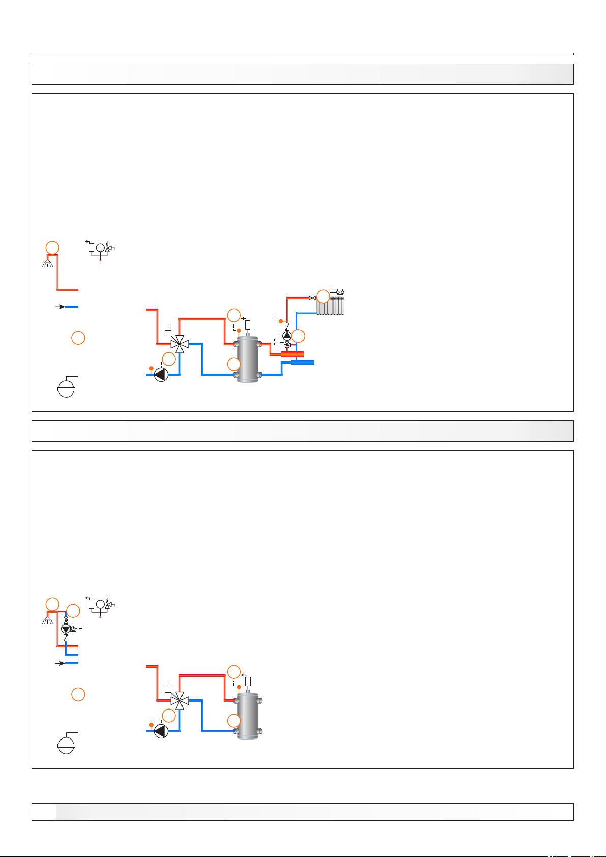
Configurations
13.99. CONFIGURATION K-7-1
7
bar
4
1
M
3
2
EKO-CKB P
1 - Boiler EKO-CKB P + Cm Pelet-set
2 - Hydraulic crossover (CRO)
3 - 4-way mixing valve + actuator (MVAL2) +return flow temp. sensor (CIRCUIT2) + pump (P1)
(return flow protection)
4 - CRO temp. sensor (BUFFER1)
5 - Mixing heating circuit
6 - 1. circuit flow sensor (CIRCUIT1) + pump (P4) + actuator (MVAL1)
7 - DHW tank in the boiler
Temperatures:
Boiler temp.: 80°C (70-90°C) = Tdhw
CRO temp: 75°C (65-80°C)
5
6
M
13.100. CONFIGURATION K-8-0
5
bar
6
4
1
M
3
2
EKO-CKB P
1 - Boiler EKO-CKB P + Cm Pelet-set
2 - Hydraulic crossover (CRO)
3 - 4-way mixing valve + actuator (MVAL2) + return flow temp. sensor (CIRCUIT2) + pump (P1)
(return flow protection)
4 - CRO temp. sensor (BUFFER1)
5 - DHW tank in the boiler
6 - DHW tank recirculation (P3)
Temperatures:
Boiler temp.: 80°C (70-90°C) - Tdhw
CRO temp: 75°C (65-80°C)
70
Technical instructions REGULATION Cm Pelet-set
Page 71
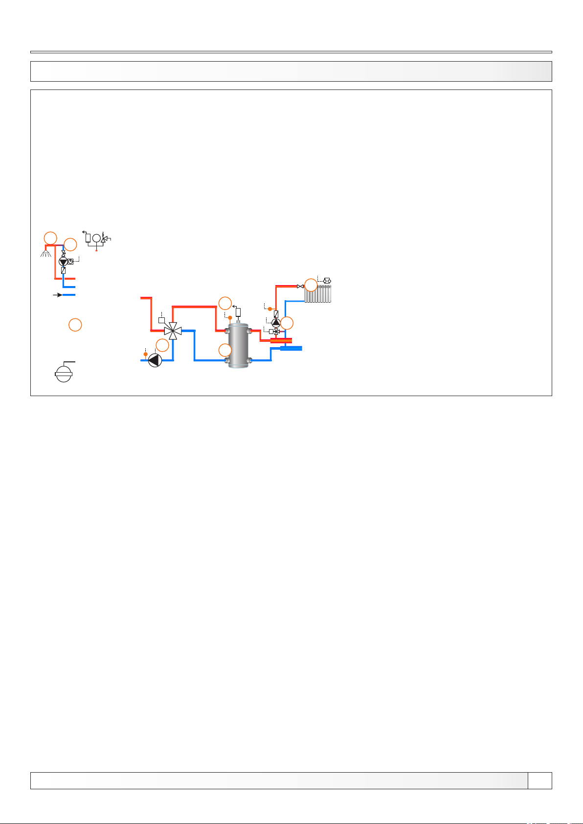
Configurations
13.101. CONFIGURATION K-8-1
7
bar
8
4
1
M
3
2
EKO-CKB P
1 - Boiler EKO-CKB P + Cm Pelet-set
2 - Hydraulic crossover (CRO)
3 - 4-way mixing valve + actuator (MVAL2) +return flow temp. sensor (CIRCUIT2) + pump (P1)
(return flow protection)
4 - CRO temp. sensor (BUFFER1)
5 - Mixing heating circuit
6 - 1. circuit flow sensor (CIRCUIT1) + pump (P4) + actuator (MVAL1)
7 - DHW tank in the boiler
8 - DHW tank recirculation (P3)
Temperatures:
Boiler temp.: 80°C (70-90°C) = Tdhw
CRO temp: 75°C (65-80°C)
5
6
M
Technical instructions REGULATION Cm Pelet-set
71
Page 72
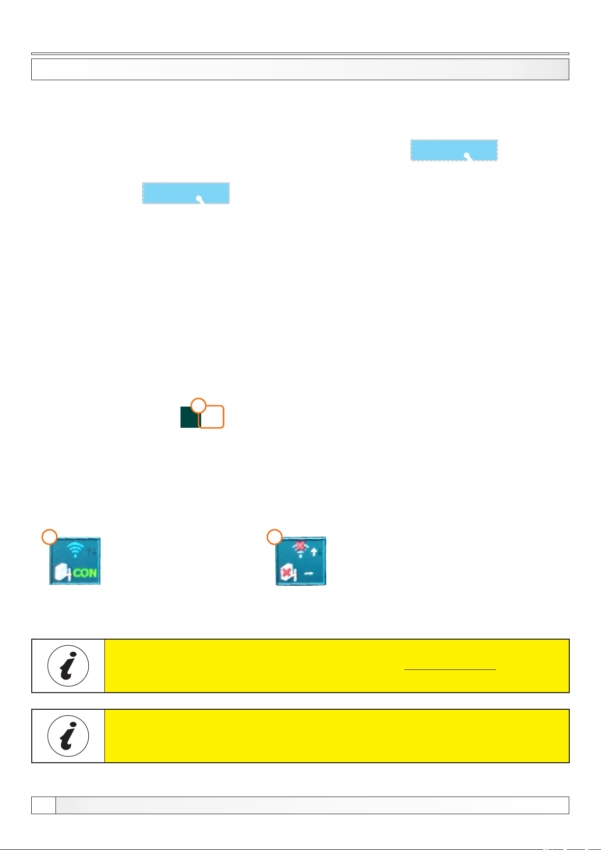
Internet supervision
5.7.1. INTERNET SUPERVISION
This option is used to connect regulation to the internet trough Cm Wifi-box via WiFi network. Cm WiFi-box is additional
equipment and is not part of standard delivery.
This option is used to enable/disable Cm WiFi-box and set its parameters.
NOTE: view in this menu depends of enabled additional equipment.
Internet supervision options:
- Factory: "Sup. + control"
- options: "OFF" / "Supervision" / "Sup.+control"
1
Regulation is connected
with web portal
(internet supervision is enabled)
IMPORTANT NOTES
Wifi network name - this option is used to enter the name of the WiFi
network you want to connect
WiFi password - this option is used to enter password of the WiFi
network you want to connect
1
Time sync. - this option is used to syncronise time betwen web portal
and boiler
Time zone - this option is used to set the time zone if boiler time zone is
different from web portal time zone
Connection reset - this option is used to reset the connection betwen
Cm WiFi-box and boiler
1
Regulation is not connected
with web portal
(internet supervision is not enabled)
72
CM WiFi-box requires active DHCP server of Access Point (e.g. router)
because manual setting of network parameters is not possible. For more
informations contact administrator of your home network
For detailed configuration of the Cm WiFi-box please refer to the Cm WiFibox manual received with the Cm WiFi box.
Technical instructions REGULATION Cm Pelet-set
Page 73
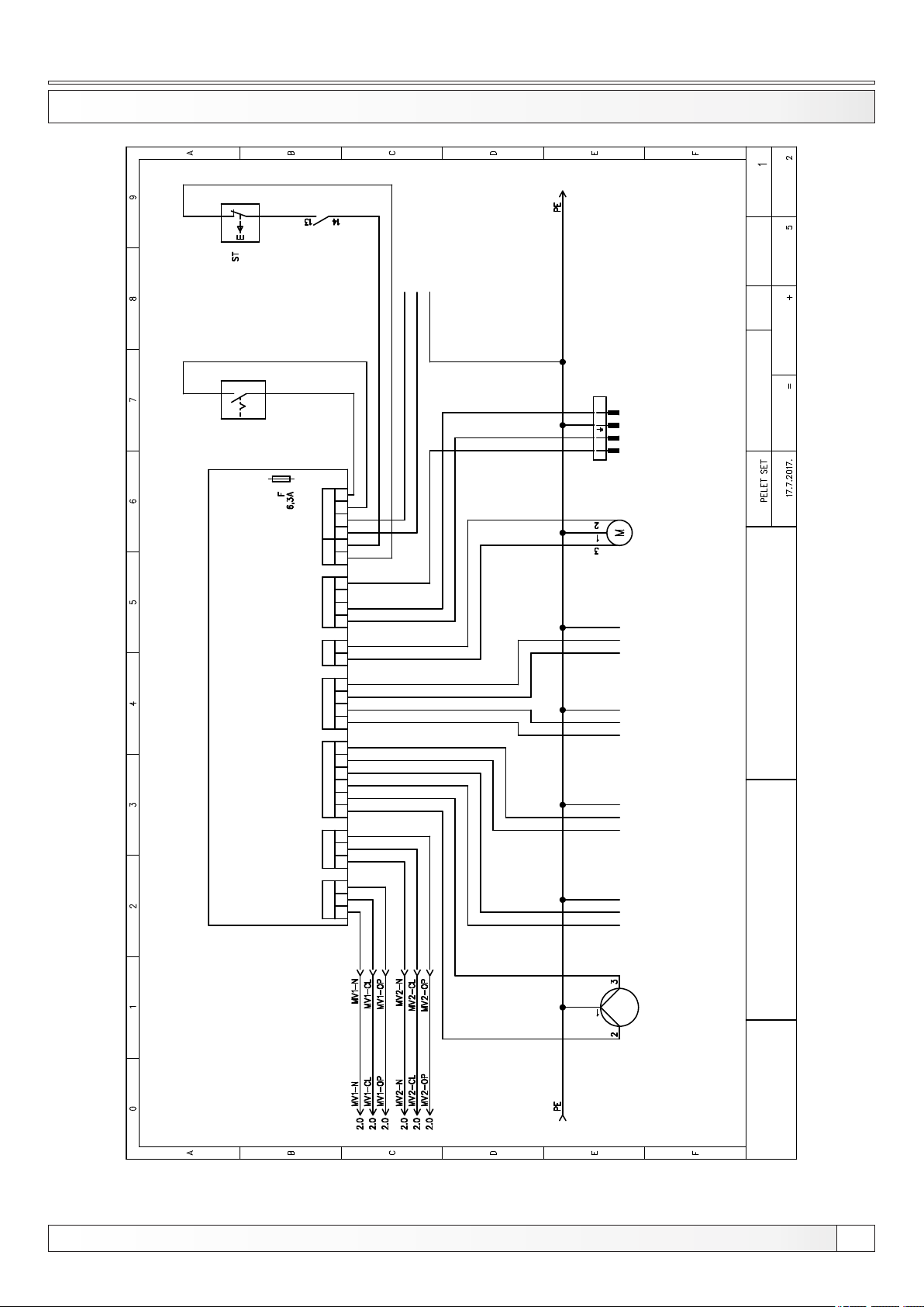
Electric scheme
ELECTRIC SCHEME 1/6
SAFETY
THERMOSTAT
MAIN
SWITCH
DOOR
MICRO SWITCH
Next sheet:
Sheet:
23 0V
POWER SUPPLY
Total sheets:
L
N
PE
MALE
4P BLACK
NL2
TO THE
BURNER
CONNECTION
4 P O LE
L1
MALE
BLACK
Rev.:
Init.:
Location:
Drawing number:
Function:
OUTPUTS
PEL ET SE T
Project:
Date:
INOU T
ST B
BUR NER1 PO W1
SCR EW
M V AL1 M V AL 2 PUM PS1 PUMP S2
N N N N N N N N N NOPCL CLO P P1 P2 P 3 P4 P 5 SC H SC F L1 SW S W
L N PE
L N PE
L N PE
L N PE
PEL LET
TR A NSP OR TER
P 5
P 4
P 3
OUTPUT OUTPUT OUTPUT
P 2
OUTPUT
C P R E G
REGULATION SCHEME
Technical instructions REGULATION Cm Pelet-set
1
PUM P
CENTROMETAL
73
Page 74
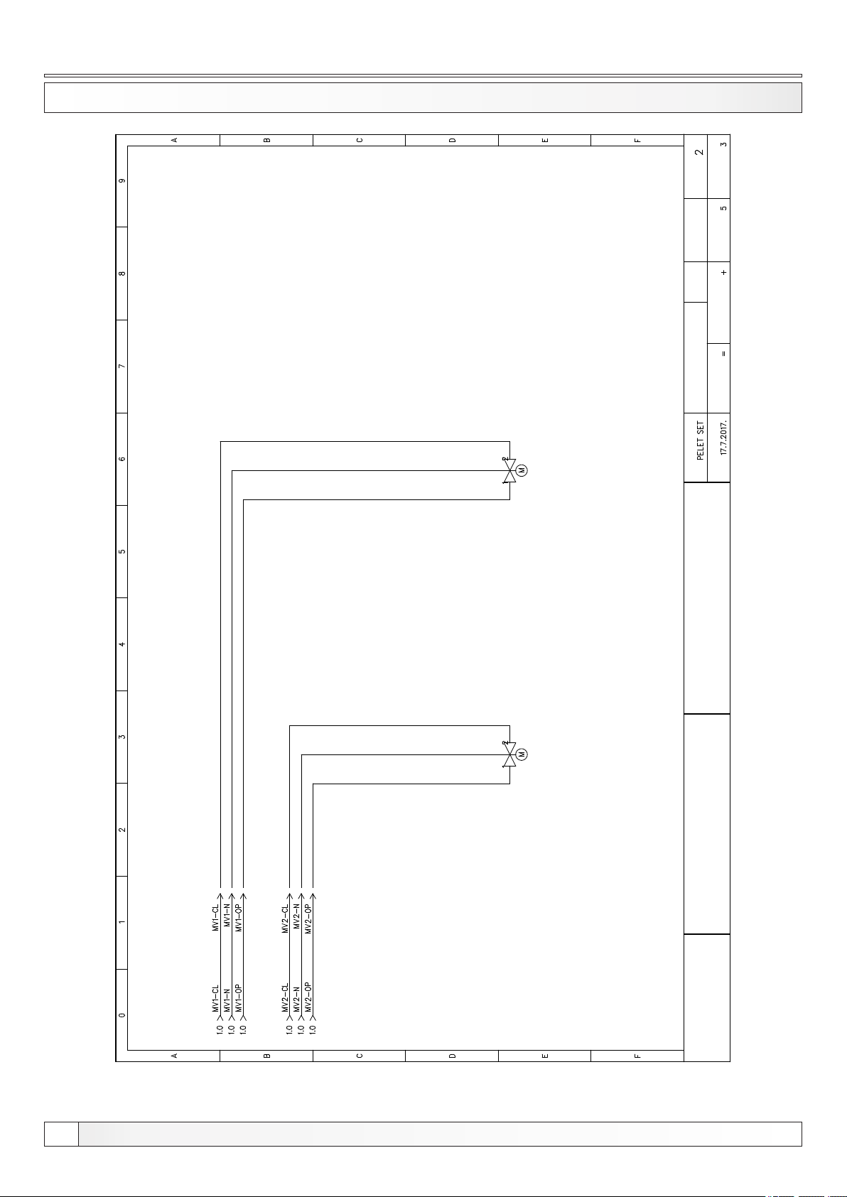
ELECTRIC SCHEME 2/6
Electric scheme
Next sheet:
Sheet:
Total sheets:
Rev.:
Init.:
Location:
Drawing number:
Function:
MIXING VALVE 1
MIXING VALVE 2
ACTUATOR
ACTUATOR
Project:
Date:
C P R E G
REGULATION SCHEME
74
CENTROMETAL
Technical instructions REGULATION Cm Pelet-set
Page 75
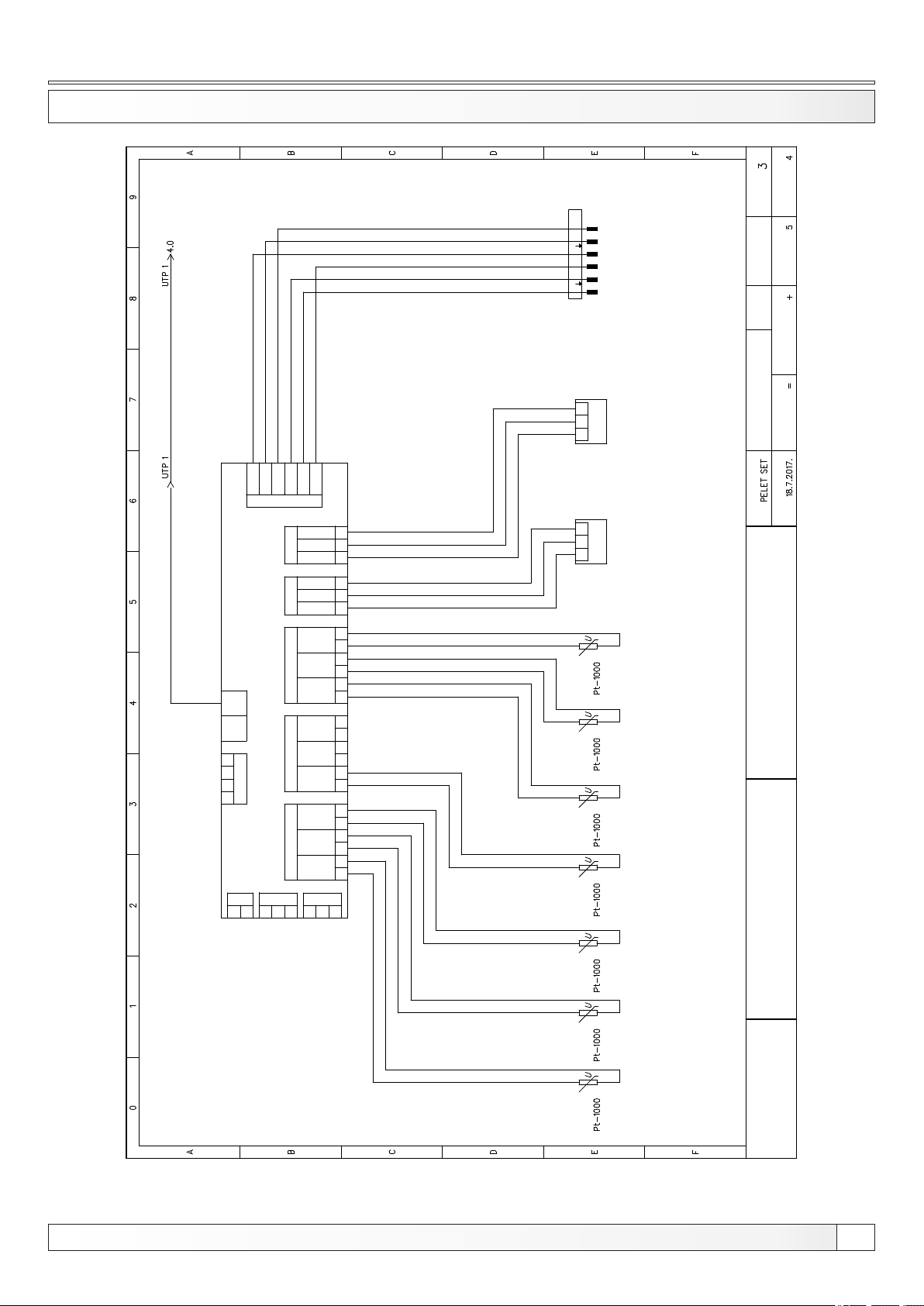
Electric scheme
ELECTRIC SCHEME 3/6
Next sheet:
MALE
6P BLACK
Sheet:
CMS R50
PRE SS.
PHO TO .
BURN ER2
L1 N
L1 N
6 P OLE
MALE
BLACK
TO THE
BURNER
CONNECTION
Rev.:
Init.:
Total sheets:
Location:
S K
1 2 3
+5 V
GND
RPM
TE MP.
GND
PO S.
TE MP.
GND
PO S.
OU TSIDE
CIRC UIT 2
CIRC UIT1
1 2 3
ROOM
CORRECTOR
S K
ROOM
CORRECTOR
SENSOR
OUTSIDE
PT 100 0
Drawing number:
Function:
Project:
Date:
BUS BUS
RJ 45 RJ4 5
TEM P2 TEM P3 CO R1 CO R2
PEL ET SE T - INPUTS
BUS
B A G 12V
TEM P1
KE Y EX T1 EX T 2
01 0 2 5V IN G
12V
SP ARE 2
SP ARE1
BUF FER2
BUF FER1
DH W
BOI LER
S S S S S S S S SG G G G G G G G G 1 12 23 3
C P R E G
REGULATION SCHEME
SENSOR SENSOR SENSOR SENSOR SENSOR
SENSOR
PT 100 0 PT 100 0 P T 100 0 P T 100 0 P T 100 0 P T 100 0
CENTROMETAL
Technical instructions REGULATION Cm Pelet-set
75
Page 76
ELECTRIC SCHEME 4/6
Electric scheme
Next sheet:
Sheet:
Total sheets:
Rev.:
Init.:
Location:
Drawing number:
Function:
Project:
Date:
T F T D I S
U T P1 U S B 1
C P R E G
REGULATION SCHEME
76
CENTROMETAL
Technical instructions REGULATION Cm Pelet-set
Page 77
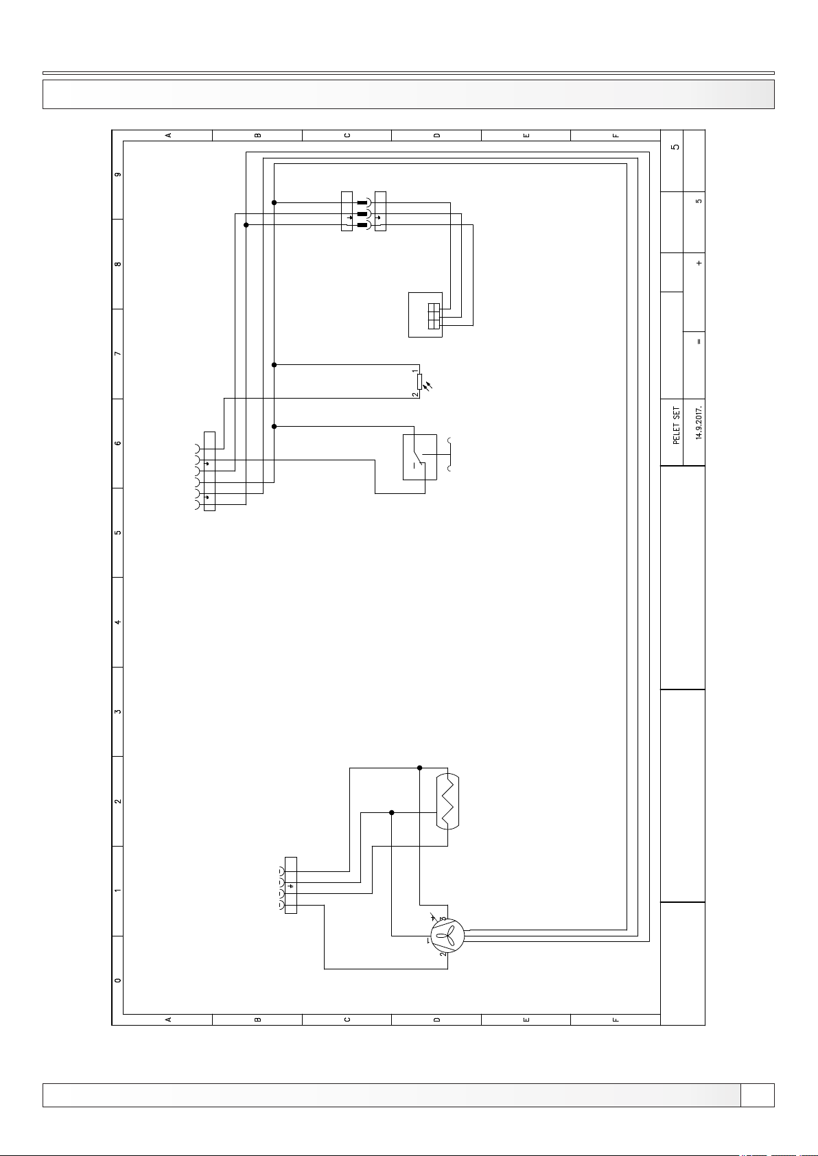
Electric scheme
ELECTRIC SCHEME 5/6 - CPPL 14-50
MALE
3P GREEN
L1 N
GREEN
3 P O LE
FEMALE
6P BLACK
NL1 L1 N
MALE
FEMALE
3P GREEN
NL1
3 P OLE
GREEN
FEMALE
FILLING AND
TEMPERATURE
SENSOR
2
Next sheet:
Sheet:
Total sheets:
Rev.:
WHITE
GREEN
BROWN
Init.:
1
GND
SENSOR
FILLING AND
SIG
TEMPERATURE
3 2
+5V
PHOTOCELL
3
1
PRESSURE SWITCH
Location:
Drawing number:
Function:
Project:
Date:
6 P O LE
BLACK
FEMALE
4 P O LE
FEMALE
4P BLACK
L1 NL2
BLACK
FEMALE
GREEN
BROWN
WHITE
C P P L 1 4 - 5 0 K W
BURNER SCHEME
Technical instructions REGULATION Cm Pelet-set
FAN WITH
RPM SENSOR
CENTROMETAL
77
Page 78
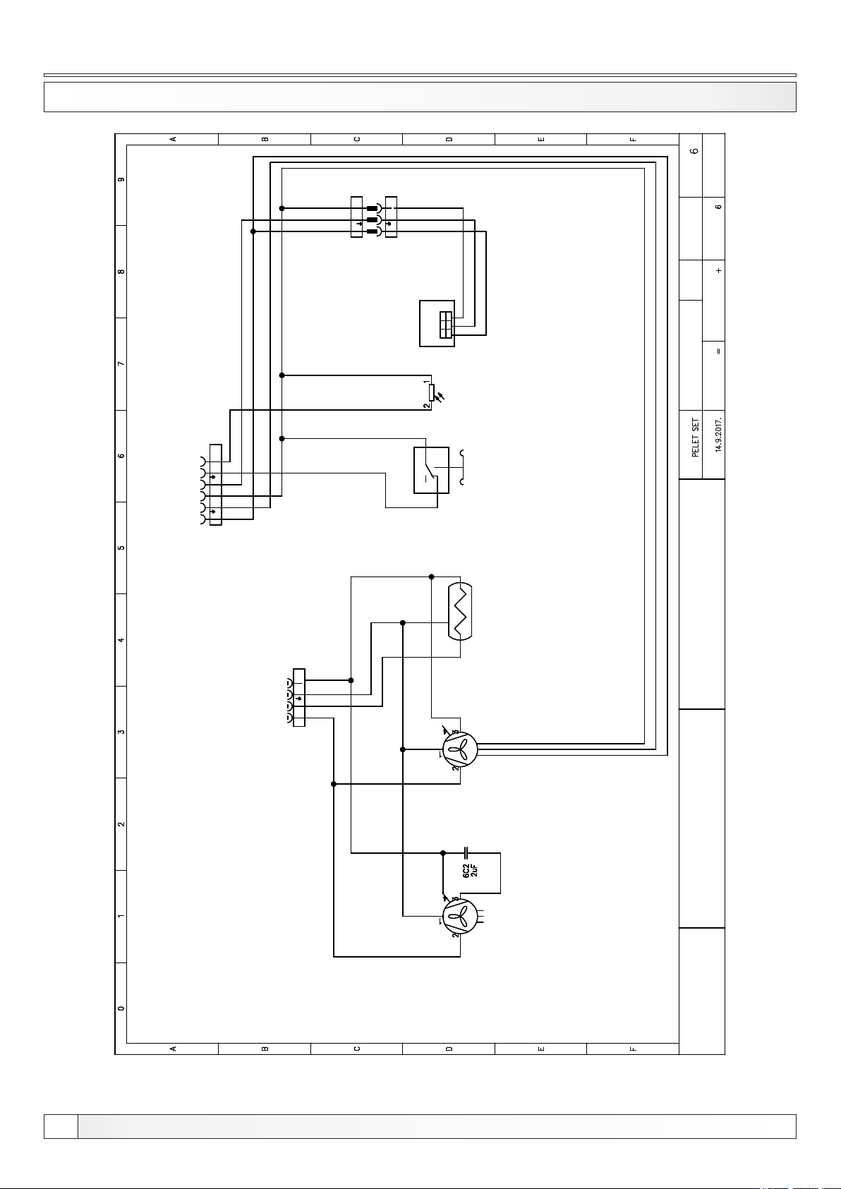
ELECTRIC SCHEME 6/6 - CPPL 90
MALE
3P GREEN
L1 N
GREEN
3 P O LE
FEMALE
6P BLACK
NL1 L1 N
MALE
3P GREEN
NL1
3 P O LE
FEMALE
GREEN
FILLING AND
TEMPERATURE
FEMALE
SENSOR
Electric scheme
Next sheet:
Sheet:
Total sheets:
Rev.:
WHITE
GREEN
BROWN
1
GND
SENSOR
FILLING AND
SIG
TEMPERATURE
3 2
+5V
PHOTOCELL
3
1
2
PRESSURE SWITCH
Init.:
Location:
Drawing number:
Function:
Project:
Date:
6 P O LE
BLACK
FEMALE
4 P O LES
FEMALE
4P BLACK
L1 NL2
BLACK
FEMALE
YELLOW/GREEN
BLUE
BLACK
SENSOR
FAN WITH RPM
BROWN
WITHOUT
ADDITIONAL FAN
RPM SENSOR
GREEN
BROWN
WHITE
C P P L 9 0 K W
BURNER SCHEME
78
CENTROMETAL
Technical instructions REGULATION Cm Pelet-set
Page 79

Notes
NOTES
Technical instructions REGULATION Cm Pelet-set
77
Page 80
120°C
30%
80°C
1700
15k
Centrometal d.o.o. assumes no responsibility for possible inaccuracies in this book originated typographical errors or rewriting, all the pictures and diagrams are principal and it is necessary to adjust each actual
situation on the field, in any case the company reserves the right to enter their own products such modifications as considered necessary.
60°C
70°C
55°C
0%
50°C
Centrometal d.o.o. Glavna 12, 40306 Macinec, Croatia
central tel: +385 40 372 600, fax: +385 40 372 611
service tel: +385 40 372 622, fax: +385 40 372 621
www.centrometal.hr
e-mail: [email protected]
TURPS- 08/2017-v1_20-ENG
HEATING TECHNIQUE
 Loading...