

Centrometal BioTec Plus 25, BioTec Plus 35, BioTec Plus 45 Installation, Use And Maintenance Manual
Page 1
TECHNICAL INSTRUCTIONS
for installation, use and maintenance
of hot water boiler
and installation additional equipment
BioTec Plus
HEATING TECHNIQUE
Centrometal d.o.o. - Glavna 12, 40306 Macinec, Croatia, tel: +385 40 372 600, fax: +385 40 372 611
TUBTP-01-2018-eng
Page 2
These instructions are an integral part of this product. All rights reserved.
Reproduction of content of this document and transfer to third parties is
not allowed without written approval from manufacturer. Make sure the
instructions are always with the device, even if its sale / transfer of another
owner to the user or staff authorized for maintenance or repairs to consult.
i
READ THESE INSTRUCTIONS CAREFULLY BEFORE
INSTALLING THE BOILER TO HEATING SYSTEM!
Boiler must not be used by children or disabled persons (either
physicallyor mentally), as well as by person without knowledge or
experience, unless they are under control or trained by s person
responsible for their safety. Children must be supervised in the
vicinity of the product.
Boiler must not operate in flammable and explosive environment.
Before any work on the boiler, electric energy must be switched off.
Insufficient combustion air for chimney vent boilers with room air for
combustion can lead to dangerous conditions.
Make sure that the combustion air supply and discharge openings
are not reduced or closed off.
Keep doors to the boiler room closed.
Protect the boiler room and avoid rodents and birds from entering
and blocking the air openings.
Boiler cannot be placed in operation until above points are not met.
Technical instructions BioTec Plus
2
Page 3

BioTec Plus 35
45
TIP
(kW)
(kW)
(kW)
(Pa)
(lit.)
(°C)
(°C)
(°C)
(°C)
(kg/s)
(kg/s)
(kg/s)
(kg/s)
(h)
(h)
(°C)
(°C/bar)
(°C)
(mbar)
(%)
(lit.)
(mm)
(lit.)
(lit.)
(lit.)
(W)
(W)
(W)
(W)
(W)
(W)
(W)
(W)
(V~)
(Hz)
(A)
(kg)
(bar)
(bar)
(°C)
(mm)
(pcs.)
(R)
(R)
(R)
(R)
25
25
12,5-25
7,5-25
138
90-170
90-130
70-110
60-110
0,019
0,0206
0,010
0,0055
3,5
-
12,8
90
1,6
10,4
80
1100
110
60
5
1100
45
30
5
5,1
750
150
8
35
17 -3,5 5
10,2-35
167
90-170
90-130
70-110
60-110
0,022
0,030
0,012
0,0080
4
-
25,1
144
1,6
10,4
148
1100
116
68
5
1100
48
33
5
5,1
875
160
10
45
22,5-45
13,5-45
187
90-170
90-130
70-110
60-110
0,027
0,0385
0,014
0,0121
4
-
41,6
176
2,5
20,2
148
1100
122
75
5
1100
50
35
5
5,1
930
180
10
600×250×600 600×400×600 600×400×735
Boiler
connections
Flow and return pipe (male thread)
Charge/discharge (female thread)
Heat exchanger connector (male thread)
Connector of exchanger sensor (female thread)
WOOD: A by 303-5:2012; B by EN ISO 17225-5:2014-09
WOOD PELLETS: C1 by EN 303-5:2012; A1 by EN ISO 17225-2
Nominal heat output
Heat output range (wood)
Heat output range (wood pellets)
Boiler class (wood / wood pellets)
Required chimney underpressure
Water amount in boiler
Exhaust gas temperature at nominal heat output (wood)
Exhaust gas temperature at nominal heat output (wood pellets)
Exhaust gas temperature at minimal heat output (wood)
Exhaust gas temperature at minimal heat output (wood pellets)
Exhaust mass flow at nominal heat output (wood)
Exhaust mass flow at nominal heat output (wood pellets)
Exhaust mass flow at minimal heat output (wood)
Exhaust mass flow at minimal heat output (wood pellets)
Minimum operating time at rated power (nominal Q ) (wood)
N
Minimum operating time at rated power (nominal Q ) (wood pellets)
N
Min. inlet water tem. at the boiler supply water connection
Cold water tem. and pressure for safety heat exchanger
Setting range for temperature controller (wood / wood pellets)
Boiler resistance on water side at nominal output (dT=10°C)
Fuel moisture content
Fuel size
Fuel loading chamber capacity (wood)
Fuel loading chamber dimensions (D×W×H) (wood)
Firebox volume (wood pellets)
Combustion chamber volume (wood pellets)
Pellet tank volume
Combustion chamber type
Required minimum accumulation volume (tank) next to boiler
Maximal electrical power input (wood)
Auxiliray power requirements at Q (wood)
N
Auxiliray power requirements at Q (wood)
min
Standby power (wood)
Maximal electrical power input (wood pellets)
Auxiliray power requirements at Q (wood pellets)
N
Auxiliray power requirements at Q (wood pellets)
min
Standby power (wood pellets)
Supply voltage
Frequency
Max. electrical current
Current type
Total mass - (boiler with casing and accessories)
Max. operating overpressure
Test pressure
Max. operating temperature
Flue gas tube - external diameter
Number of turbulators
Heating appliance working
Heating appliance working
5
10
60
10-15°C / 2 bar
max. 90 / 65 - 90
max 25 % for wood, max. 12% for wood pellet
(450-550) x 70 x 50 for wood, fi6
underpressure
by EN 303:2012-point 4.4.6
230
50
~
2,5
5,5
90
6/4"
3/4"
3/8"
1/2"
with fan
under non-condensing conditions
Fuel type
15
3
Technical instructions BioTec Plus
Page 4
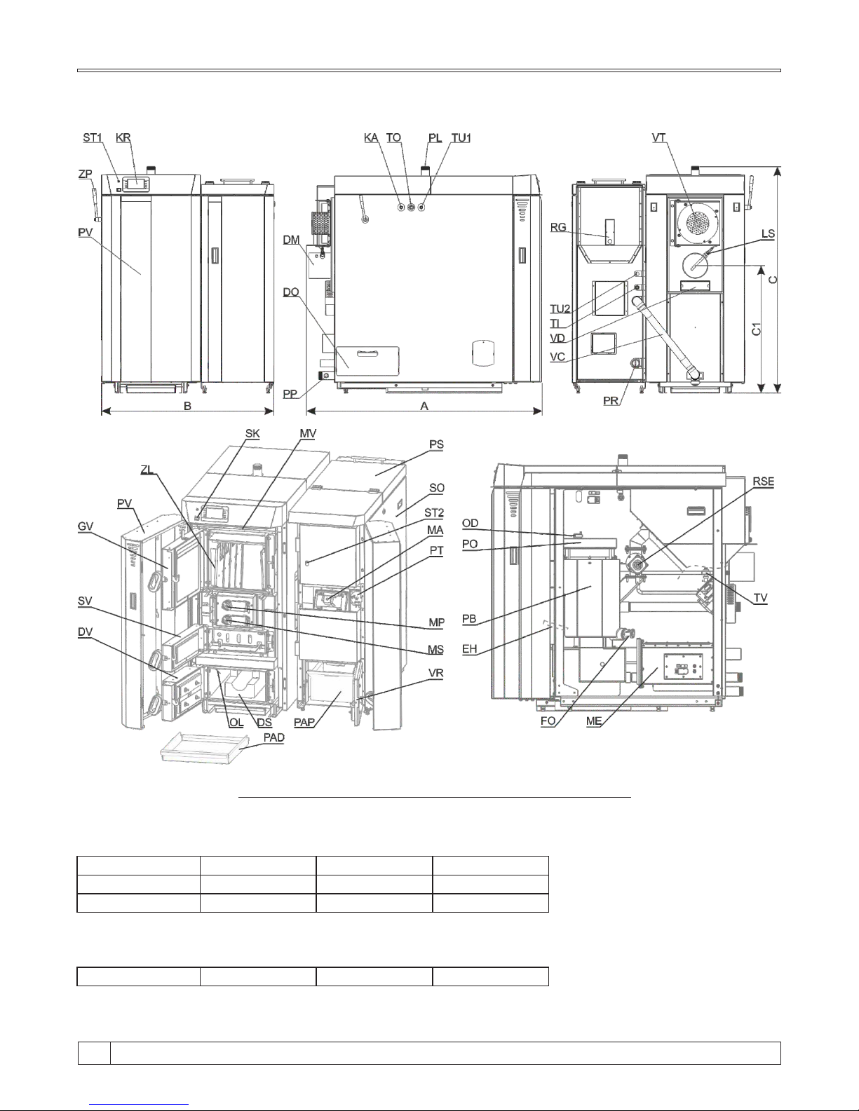
Boiler
dimensions
(A)
Depth
(B)
Width
(C)
Height
Other
dimensions
(C1)
Height
1450
1260
1585
1260
1450
1255
1450
760
1605
1055
1350
760
BioTec Plus 25 / 35
BioTec Plus 45
BioTec Plus 35
BioTec Plus 25
INNER PARTS VIEW FOR BOILERS BioTec Plus 25-45
Technical instructions BioTec Plus
4
Page 5
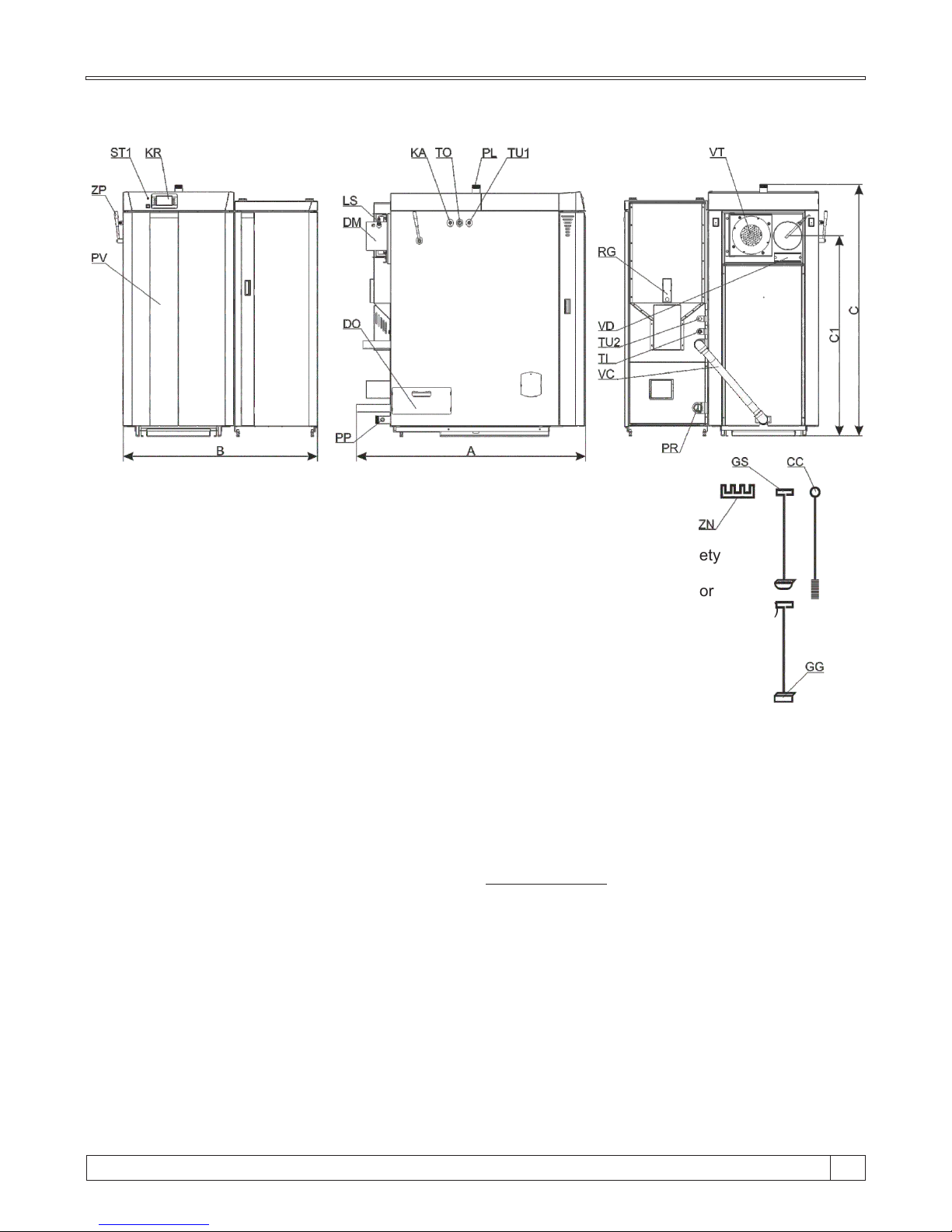
BioTec Plus 45
DM - Flue gas tube connection
DO - Cover of lower openings of the flue gas chamber
DS - Lower refractory stone (chamotte) (2 parts)
DV - Lower boiler door (wood)
EH - Electric heater (pellets)
FO - Photocell
GV - Upper boiler door (wood)
KA - Heat exchanger connection (safety cooling
system) (wood)
KR - Digital boiler controller
LS - Lambda probe
MA - Magnetic valve
ME - Cleaning mechanism assembly (pellets)
MP - Primary air actuator
MS - Secondary air actuator
MV - Upper door microswitch
OD - Air-vent
OL - Combustion chamber temperature sensor
PAD - Ash tray (wood)
PAP - Ash tray (wood pellets)
PB - Pellet burner
PL - Main flow
PO - Door for cleaning of pellet burner
PP - Filling / drainage
PR - Return flow
PS - Pellet tank cover
PT - Pressure switch
RG - Fuel level sensor (pellet)
RSE - Backfire protection valve (RSE)
SK - Main switch
SO - Casing cover (removable) for acces to electric
parts (pellets)
ST1 - Safety thermostat (wood)
ST2 - Safethy thermostat (wood pellets)
SV - Middle boiler door (wood)
TI - Heat exchanger output (safety
cooling system) (pellet)
TO - Thermal safety valve sensor
connection (safety cooling system) (wood)
TU1 - Heat exchanger connection thermal safety valve connection point
(safety cooling system) (wood)
TU2 - Heat exchanger input (safety
cooling system) (pellet)
TV - Built-in thermal safety valve (safety cooling
system)
VC - Connection tube
VD - Opening for cleaning of the flue gas chamber
VR - Lower boiler door (pellet)
VT - Fan
ZL - Sheet metal protection cover (wood)
ZP - Flue gas tube cleaning lever
CLEANING SET:
CC - Flue gas tubes cleaning brush
GG - Scraper for upper refractory stone (chamotte),
flue gas chamber and place around lower chamotte
cleaning
GS - Scraper for cleaning of the lower refractory stone
(chamotte)
ZN - Holder for cleaning set
15
5
Technical instructions BioTec Plus
Page 6

1.1. CHARACTERSTICS OF THE BioTec Plus BOILER
1.0. GENERAL
The BioTec Plus boiler is produced in compliance with the EN 303-5:2012 norm, which enables
the required level of functioning and minimal environmental pollution, through the firing with wood
logs and wood pellets. The system of flue gases conduction and their additional burning out,
enables its high efficiency, which makes this product extremely economical.
Widely sized left side fuel loading door enables firing with large pieces of wood logs and very
simple and easy cleaning and maintenance. The wood gasification principle enables a complete
fuel burning so maintenance of left part of the boiler is set to minimum. One filling of logs lasts up to
4 hours, depend about nominal heat output. There is also a possibility of prolonging the firing
process to the entire day, if the heating requirement is decreased. The boiler can keep the glow up
to 12 hours (depends on the quality of the wood), during which period it is not necessary to repeat
the start firing process.
In the right side of the boiler is installed the burner for wood pellet firing with the automatic firing
and automatic self-cleaning function which enables the reliable operation also with the low quality
wood pellets.
The boiler must be connected to the central heating system with return flow protection and with
properly sized water accumulation tank(s).
Boiler operation is managed with inbuilt boiler control unit using two boiler sensors, sensor in
combustion chamber, flue gas sensor and lambda probe, motors for primary and secondary air
intake for combustion and modulating underpressure fan on flue gases outlet from boiler. Boiler
control unit can run return flow protection, buffer tank management, one heating circuit with
circulation pump and 3-way mixing valve with actuator steered by outer temperature sensor and
room corrector and DHW water heater tank pump.
With boiler BioTec Plus it is easy to handle, integrated control unit with color touch screen assures
reliable and simple boiler operation. With installed accumulation (buffer) tank excess of produced
heat is accumulated into the tank and can be consumed when needed. Because of accumulation
tank, firing of the wood can be planned in a reasonable time, and in the case of mild outside
temperature, space heating and DHW heating without firing boiler is also possible for several
days, or just start pellet side of the boiler.
The boiler is delivered together with thermal insulation, covered by a metal casing on two wood
pallets.
Steel hot water boiler BioTec Plus has two separate combustion chambers inside the common boiler
water chamber. Boilers BioTec Plus, nominal heat output 25, 35 and 45 kW, are designed for wood
log firing in left part and wood pellet firing in right part of the boiler. The wood gasification principle
enables a complete fuel burning in left part of the boiler. Logs up to 550 mm long can be inserted into
the large combustion chamber. The burning period of a single fill of logs is up to 4 hours, depend
about nominal heat output. The boiler can keep the glow even 12 hours, which means that in this
period it is not necessary to fire up the boiler in order to keep the heating process. In the right side of
the boiler is installed the burner for wood pellet firing with the automatic firing and automatic selfcleaning function which enables the reliable operation also with the low quality wood pellets. Boiler
operation is controlled with inbuilt boiler control unit using two boiler sensors, sensor in combustion
chamber, flue gas sensor and lambda probe, motors for primary and secondary air for combustion
and modulating underpressure fan on flue gases outlet from boiler. Boiler must be connected to one
adequately designed chimney and to the central heating system with return flow protection and
adequately designed water accumulation tank (CAS).
Technical instructions BioTec Plus
6
Page 7
All local regulations, including those referring to national and European standards need to be
complied with when installing the appliance. The boiler must not be modified unless using the
tested original accessories we provide or if the work is undertaken by our Customer Service. Only
fit original spare parts. These can be obtained from your customer service partner or directly from
ourselves. European standards need to be complied with when installing the appliance.
Regular care and cleaning of the appliance, flue gas outlets, connecting piece and flue.
CAUTION:
The flue may block if the boiler is heated again after a long period of it not being used. Before
starting the boiler, have the flue checked by a specialist (chimney sweep). Ensure sufficient
supply of fresh air in the installation room when heating. The air must be replaced at least 0.8
times an hour through constant and reliable room venting. Fresh air may have to be provided from
outside if the windows and doors in the room where the boiler is installed are well sealed or if this
room contains other equipment, such as extractor hoods, clothes dryer, fan etc.
1.2. SAFETY PRECAUTIONS
1.3. IMPORTANT INFORMATIONS
This symbol indicates measures for protection against accidents and warning
for the user and / or exposed persons.
The boiler and related accessories are state of the art and meet all applicable safety regulations.
The control unit, wiring chamber, el. heater, safety cut-out STB thermostat, fan, grid cleaning
mechanism, flue gas tubes cleaning mechanism and pellet supply mechanism are integrated into
the BioTec Plus. They are operate at a voltage of 230V AC. Improper installation or repair can
pose the danger of life-threatening electric shock. Installation may beperformed only by
appropriately qualified technicians.
Caution symbols:
Please take careful note of the following symbols in this Operating Manual.
Concerning the specific need of sanitary hot water, the BioTec Plus boiler can be connected to one
of water heaters produced by our company. We suggest the combination with wall hanged SKB
Digi or LKB Digi water heaters, as well as with floor standing TB water heaters or accumulation
tanks CAS-B. If the future connection to the solar system has been planned, boiler can be
connected to combined accumulation tank CAS-BS or STEB solar water heater. Boiler is tested
and certified according to the European standard EN 303-5:2012 and meets class 5. It is
manufactured in compliance with ISO 9001 and ISO 14001 standards.
Although the boiler has two separate furnaces, boiler connects to one properly selected chimney.
15
7
Technical instructions BioTec Plus
Page 8

1.4. WOOD GASIFICATION COMBUSTION PROCESS (wood side)
Combustion process is carried out in double combustion chamber in several phases. After filling
the upper chamber with logs, glow dry the logs, and at temperature 100÷300°C logs are beeing
gasified. The gases created in such process are mixed with the oxygen from air and burn out
completely with high temperature.
Fuel: wood logs with moisture content up to 20% (max. 25%), minimum size must be bigger than
a nozzle in refractory stone (chamotte) of the upper chamber. This demand for moisture content is
fulfilled with wood dried on air at least 12 months.
Wood pellets are used as fuel in right side of BioTec Plus boiler. Wooden pellets are bio-fuel made
of wooden wastes. Pellets can be packed in different packaging: in bags (15 kg or 1000 kg), or as
3
bulk in large (underground) tanks ( 4 - 15 m ) or in basement spaces. Recommended properties of
pellets for firing in BioTec Plus boilers are the following:
- heating value >= 5 kWh/kg (18 MJ/kg)
-diameter <= 6 mm
-max. moisture content <= 12 %
-max. dust content <= 1,5 %.
1.5. FIRING PROCESS IN WOOD PELLET SIDE
Technical instructions BioTec Plus
8
Page 9

2.0. DELIVERY PACKAGE
Boiler BioTec Plus is delivered in parts for easier transportation and mounting to boiler room.
Basic equipment is delivered seperately:
- left part of the boiler for wood firing with mounted thermal insulation (on wood pallet) with
inbuilt:
- color touch screen display control unit
- sensor in combustion chamber
- flue gas sensor
- boiler sensor
- lambda probe
- 2 actuators for primary and secondary air
- flue gas modulating fan
- microswitch for upper boiler door
- STB safety thermostat
- right part of the boiler for wood pellet firing with mounted thermal insulation (on wood
pallet) with inbuilt:
- photocell
- cleaning mechanism with movable grate
- pellet tank
- feeder screw
- backfire protection by rotation valve (RSE)
- pellet level sensor
- magnetic valve for air
- thermal safety valve
- electric heater
- pressure switch
- STB safety thermostat
- boiler sensor
- ash tray
- Additional sensors in basic delivery:
- 2 × Buffer tank sensors
- 1 × Outer temperature sensor
- 1 × Return flow sensor
- 1 × DHW sensor
- 1 × Room corrector (CSK)
- cleaning brush, two scrapers and holder for cleaning set and portable ash tray (for left
part of the boiler (wood))
- set for connecting left and right side of the boiler: gasgets, screws, nuts.
- connection tube for connecting left and right side of the boiler
15
9
Technical instructions BioTec Plus
Page 10

25
35
45
5/4''
5/4''
5/4''
Magna3 32-60
Magna3 32-60
Magna3 32-60
6/4''
6/4''
6/4''
Recommendations for the VTC valve, circulation pump and water accumulator CAS - according
to the boiler output:
Heat output
range
(kW)
Connection
VTC 512
(outer thread)
Connection
VTC 531
(internal thread)
Circulation pump type
(like Grundfos)
Volume of CAS accumulation
tank for BioTec Plus
wood gasification boilers
Minimum 50 litres / kW of boiler
2.1. ADDITIONAL EQUIPMENT
Recommendations for the LTC units and the water accumulators CAS - according to the boiler
output:
Minimum 50 litres / kW of boiler
25, 35
45
5/4''
--
--
6/4''
Heat output
range
(kW)
Connection
LTC 261
(internal thread)
Connection
LTC 271
(internal thread)
Volume of CAS accumulation
tank for BioTec Plus
wood gasification boilers
Additional equipment is not included in basic delivery. Obligatory
additional equipment must be purchased seperately. Other additional
equipment can be purchased optionally.
i
For closed heating systems:
- Thermal safety valve
- Safety-airvent group (2,5 bar)
- Expansion vessel for closed heating systems (size according the volume of heating installation,
including buffer tank volume)
For open heating systems:
- Open expansion vessel (size according the volume of heating installation, including buffer tank
volume)
2) OTHER ADDITIONAL EQUIPMENT:
- CAL alarm box (light/speaker)
- CM2K-B module for regulation 2+ heating circuits (max. 4 units.)
- GSM alarm module for mobile network
- Room thermostat
- Automatic flue gas tubes cleaning
- Pellet suction system CVT + CentroPelet box (pellet feeding box)
- Pellet suction system CVT + Feeder screw
- Pellet tank on wheels with volume of 780 l with feeder screw for filling standard installed pellet
tank
CAL alarm box
(light/speaker)
CM2 K-B module
for regulation
2+ heating circuits
GSM alarm module
for mobile network
Room corrector (CSK)
(basic equipment)
1) OBLIGATORY ADDITIONAL EQUIPMENT:
- accumulation (buffer) tank for heating system (CAS (min. liter according to local regulation),
m ).inimum 50 litres / kW of boiler
- return flow protection - 3-way mixing valve with actuator (protection valve) or 3-way thermostat
valve (60°C) (like ESBE VTC 512, VTC 531, LTC 261, LTC 271).
Technical instructions BioTec Plus
10
Page 11
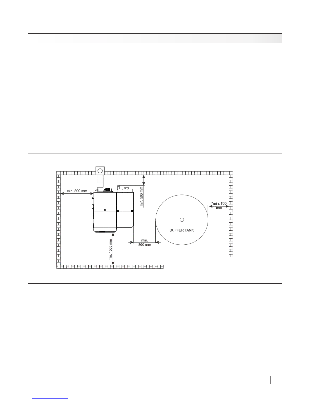
3.0. BOILER / ADDITIONAL EQUIPMENT POSITIONING AND ASSEMBLY
The positioning of the boiler has to be carried out the authorized person. We suggest the
positioning on the solid concrete basis, which height is between 50-100 mm. The boiler room has
to be absolutely protected from freezing and properly ventilated. The boiler has to be positioned in
order to enable its connecting to the chimney (see point 3.) and heating installation as well as its
servising during the functioning process, cleaning and maintenance (Figure 1). The connection of
the boiler to the central heating system is obligatory with the one or more CAS water
accumulator buffer tanks, depending of the boiler's power. It is recommended to connect
minimum 50 liters water accumulation to each 1 kW boiler power (i.e. for the 45 kW boiler
minimal water accumulation should be 2.250 liters). The boiler should not be used without being
connected to the water accumulation tank. It must be connected to the CAS water accumulator
obligatory with return flow protection through an 3-way mixing valve with actuator (protection
valve) or 3-way thermic valve (like ESBE VTC 512, VTC 531 (60°C), LTC 261, LTC 271 (60°C)).
WARNING!
Flammable items must not be placed on the boiler and within the minimum distances
shown in Figure 1.
Figure 1. Minimum distance from the boiler room walls
*valid for closest tank to the wall
15
11
Technical instructions BioTec Plus
Page 12
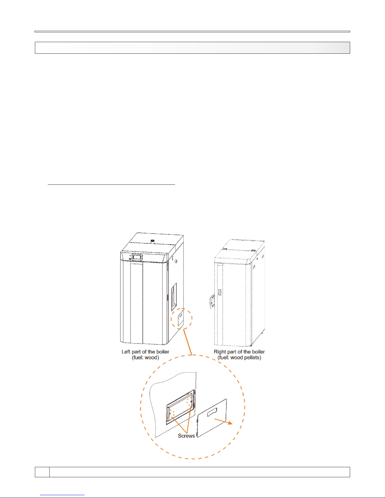
3.1. INSTALLATION OF DELIVERED PARTS
BioTec Plus is delivered on two wooden pallets. It must be mounted like is described on next
pages of these technical instructions. After the boiler is mounted, should be positioned in the
boiler room (see point 2.0.). Base protection with stone wool push under the boiler as shown in
figure 2.a.
In upper chamber of the left side of the boiler are delivered (figure 2.b):
1. holder for cleaning set and 2 cleaning scrapers and cleaning brush
2. room corrector and sensors (2 buffer tanks sensors, 1 return flow sensor, 1 DHW sensor, 1
outer sensor)
Holder for cleaning set can be positioned on lateral side of the boiler (A) or to the wall (B), near the
boiler and easy accessible. On this holder should be placed cleaning set (2 scrapers and brush).
Sensors and room corrector should be connected according heating installation and connecting
scheme.
CHECKING FLUE GAS CHAMBER LID
Before connecting of left (fuel: wood) and right (fuel: wood pellets) sides of boiler is necessary to
check if is right flue gas chamber lid it properly tight. Remove casing cover lid and additionally tight
screws on flue gas chamber lid (like is shown on figure below). Acces to right flue gas chamber will
be disabled after connection left and right side of the boiler.
Technical instructions BioTec Plus
12
Page 13
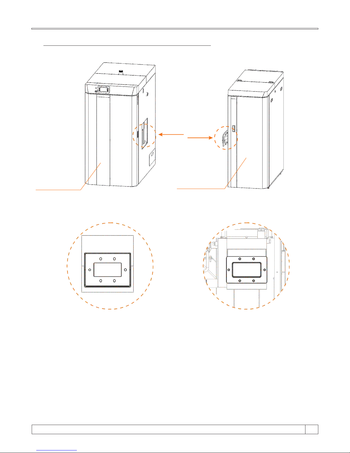
CONNECTING LEFT AND RIGHT SIDE OF THE BOILER
Left part of the boiler
(fuel: wood)
Right part of the boiler
(fuel: wood pellets)
Detail 1
Detail 2
Detail 1 Detail 2
Prepared flange with holes on left part
of the boiler. First hole (left) have circle
shape, other five holes are slitted (have
possibility for height niveling).
Prepared flange on right side of the
boiler. Flange have factory glued
gasket and factory mounted six screws
M12.
15
13
Technical instructions BioTec Plus
Page 14
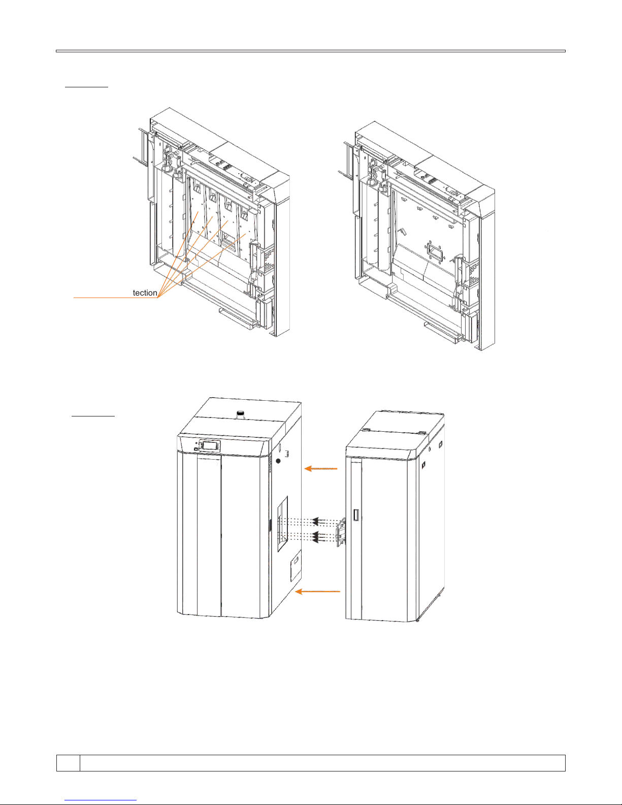
STEP 1:
Sheet metal protection
cover
BioTec Plus - left part of the boiler section view
Remove sheet metal protection cover through the upper boiler door.
STEP 2:
It’s necessary draw closer left side of the boiler to right side of the boiler. Screws from flange on right
side of the boiler must get into flange holes on left side of the boiler. See figure on the next page.
Technical instructions BioTec Plus
14
Page 15
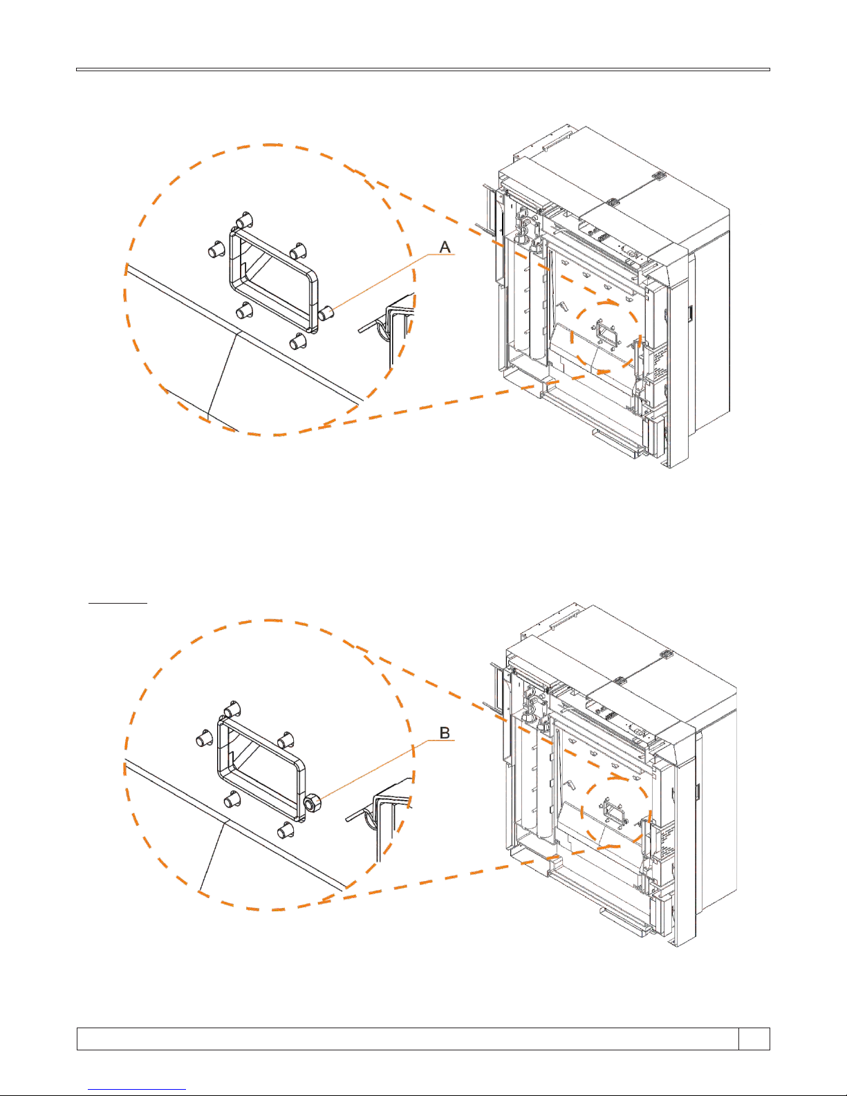
A - hole with circle shape; other holes are slitted for height niveling possibility.
Screws from flange on right side of the boiler must get into flange holes on left side of the boiler like is
showned on figure above.
BioTec Plus - left part of the boiler section view
STEP 3:
Put washer, toothed washer and nut on screw like is showned on figure above (B). Tight nut but not
completely tight.
BioTec Plus - left part of the boiler section view
15
15
Technical instructions BioTec Plus
Page 16
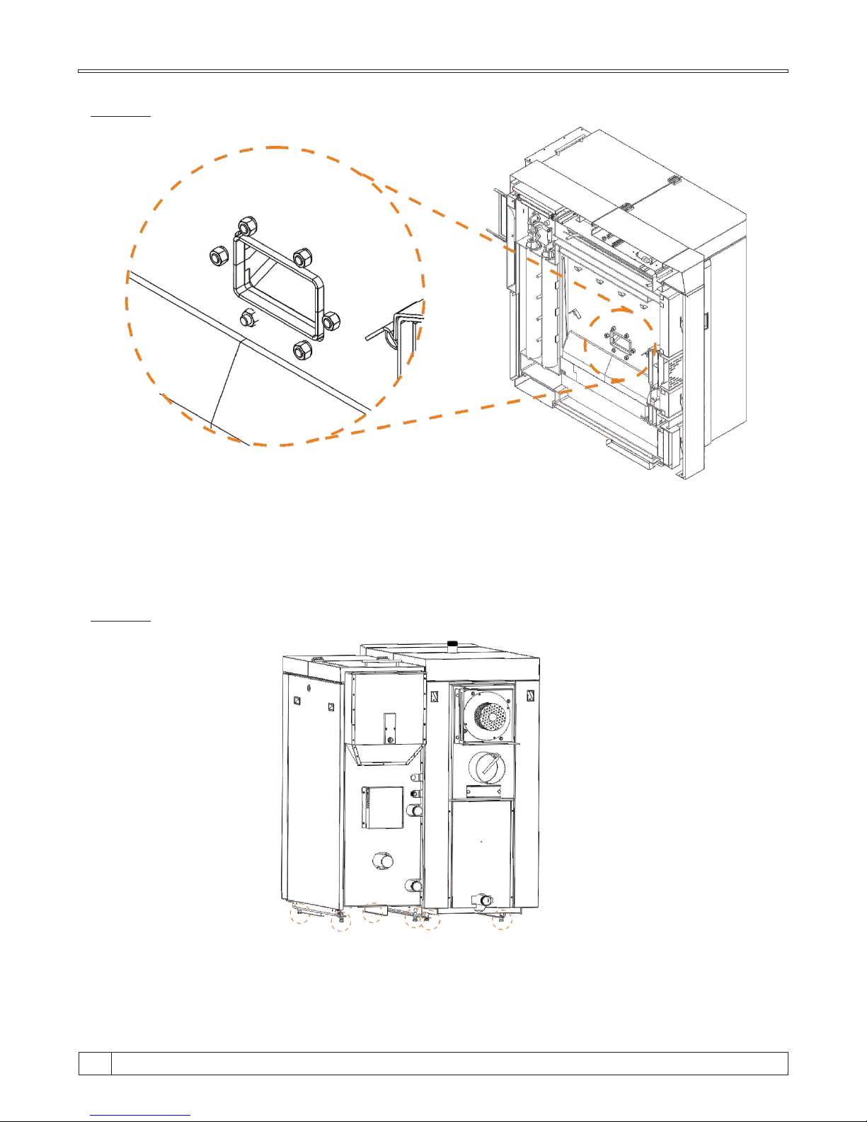
STEP 4:
BioTec Plus - left part of the boiler section view
Put washers, toothed washers and nuts on all other screws and start tigth them. If is needed, nivel
boiler (holes are slitted for niveling). Thight hard all six nuts.
STEP 5:
Left and right side of the boiler have adjustable foots. Adjust it if is necessary. Boiler foots must
touching boileroom floor.
Technical instructions BioTec Plus
16
Page 17
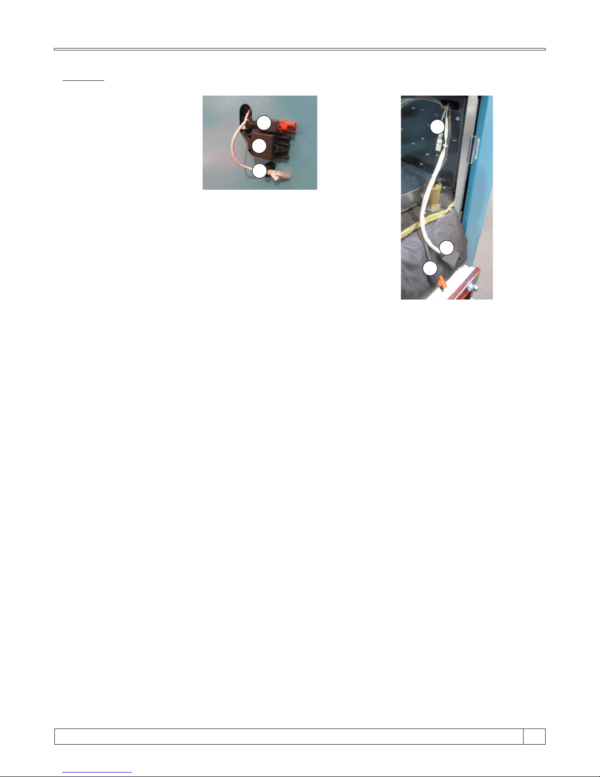
STEP 6:
1
2
3
prepared sockets on left side
of the boiler (wood)
1
2
3
prepared plugs on right side
of the boiler (wood pellets)
On left side of the boiler (wood) are prepared sockets, on right
side of the boiler (wood pellets) are prepared plugs. Cabels must
be connected in right order: 1-1; 2-2; 3-3;
15
17
Technical instructions BioTec Plus
Page 18
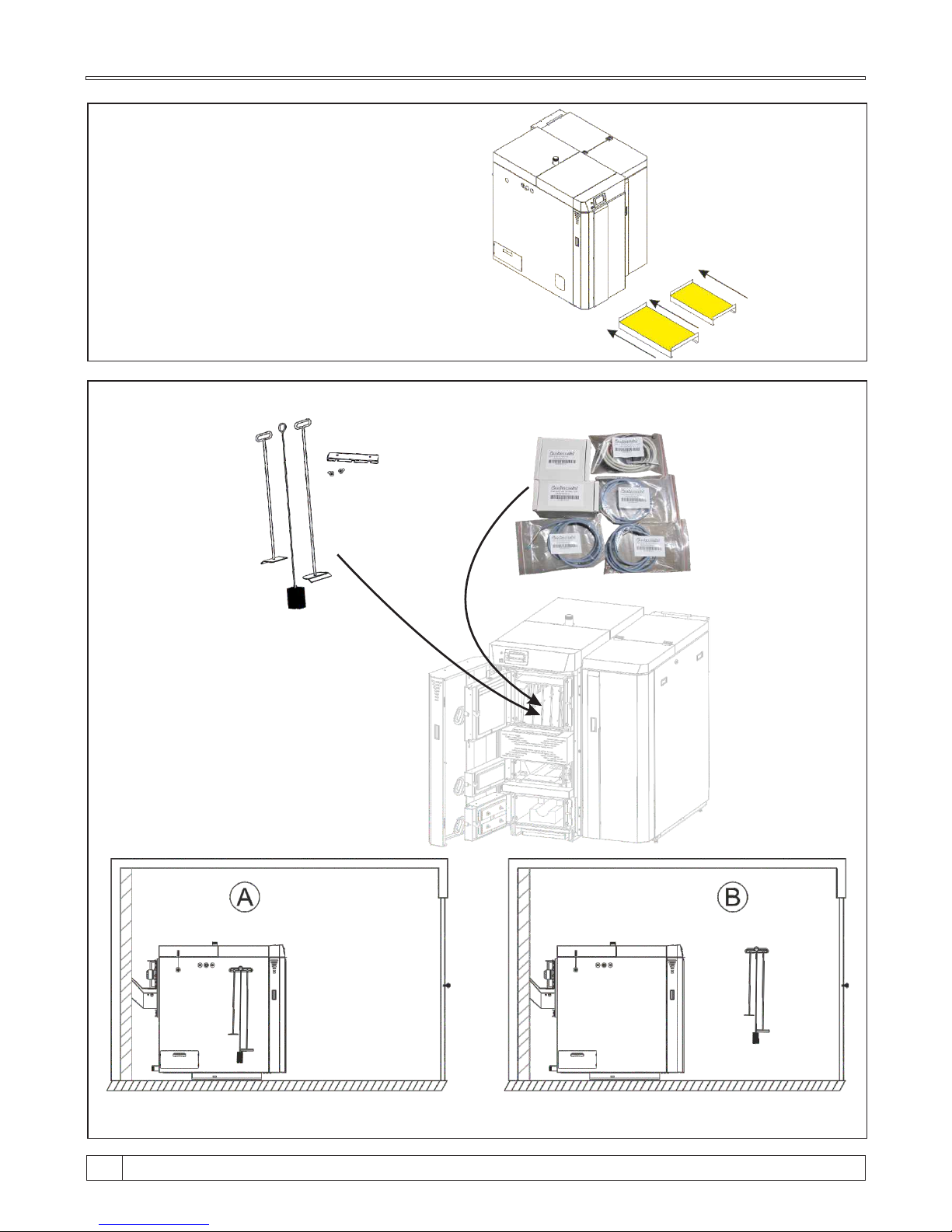
Figure 2.b Delivered parts
Cleaning set
Sensor set
Position od cleaning set - on the boiler. Position od cleaning set - on the wall.
Figure 2.a Base protection with mineral wool
Push base protection under the boiler
Technical instructions BioTec Plus
18
Page 19
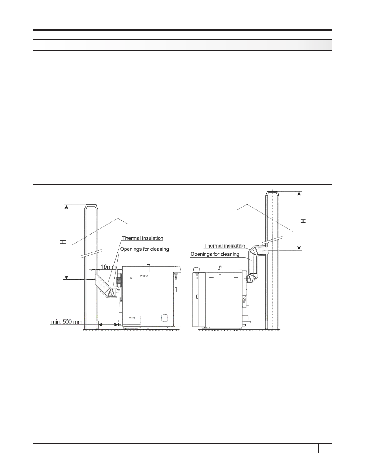
4.0. CONNECTION TO THE CHIMNEY
Properly dimensioned and built chimney is the precondition for a safe and reliable operation of the
boiler and economic heating. The chimney has to be good insulated, gas-proof and smooth. On
the lower part of the chimney, a cleaning door has to be built in. Brick layed chimney has to have 3
layers with an stone wool thermal insulation in the middle. The thickness of the insulation should
be 30 mm, if the chimney is situated inside the building, i.e. 50 mm if the chimney is situated
outside the building. Inside chimney diameter dimensions depend on its height and on the
boiler thermal output (Figure 5.). The temperature of the flue gases on chimney exit point
should be minimum 30°C higher then the temperature of their condensating point. The choice and
the construction of the chimney should be performed by an authorized person. Minimal distance
between boiler and the chimney is 500 mm. The flue gas tube has to have an inclination of 30-45°
to the chimney (Figure 3.). In order to unable entering of the condensate from the chimney into the
boiler, 10 mm of the flue gas tube length has to be inserted deaper inside the chimney. It is
obligatory to insulate the chimney connection tube with a mineral stone wool of 30-50 mm
thickness. All installation works must be made in accordance with valid national and European
standards.
H - Useful chimney height
Figure 3. - Possible connecting of the BioTec Plus boiler to the chimney
Possible way of connecting to the
chimney of the BioTec Plus 25-35 boiler
(recommendation)
Possible way of connecting
to the chimney of the Bio-Tec-L boiler
(Only BioTec Plus 45 because of position
of the fan)
15
19
Technical instructions BioTec Plus
Page 20
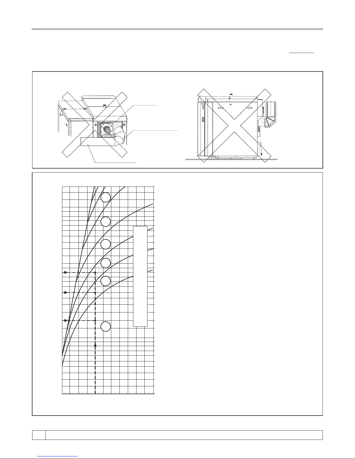
10
15
20
25
35
40
45
50
60
70
80
90
100
110
5 10 15
18
20
22
25
30
34
6 7 8 9
An example of the chimney selection:
- boiler output: 25 kW
- Fuel: wood logs, wood pellets
- required useful chimney height: H=8 m
- required inner chimney diameter: 18 cm
- boiler output: 35 kW
- Fuel: wood logs, wood pellets
- required useful chimney height: H=8 m
- required inner chimney diameter: 20 cm
- boiler output: 45 kW
- Fuel: wood logs, wood pellets
- required useful chimney height: H=8 m
- required inner chimney diameter: 22 cm
Figure 5. - Dimensioning of the chimney for BioTec Plus boilers
Useful chimney height - from flue gas tube connection
to the top of chimney
Inner chimney diameter - interior chimney diameter.
Nominal thermal output of the boiler (kW)
Useful height of the chimney (m)
Inner diameter of the chimney (cm)
At connecting a boiler to the chimney, flue gas tubes and elbows must not pass behind the fan
since in that case the cleaning and maintenance will not be possible. An example of incorrect
position of flue gas tubes and elbows in relation to the fan is presented at the Figure 4.
Figure 4. Incorrect connecting the boiler to the chimney - not possible cleaning of the fan
BioTec Plus 45
BioTec Plus 25 / 35
Fan
Flue gas elbow
Flue gas tube
Technical instructions BioTec Plus
20
Page 21

Boiler room must be equipped with an opening for supply of fresh air which is dimensioned in
accordance with boiler thermal output (minimum opening area according to below shown
equation). Such opening must be protected with a net or grate. All installation works have to be
performed in accordance with valid national and European standards. Boiler must not operate in
flammable and explosive environment.
4.1. FRESH AIR OPENING
Q - boiler output in kW
2
A - opening area in cm
A = 6,02 Q
Equation for calculate opening area:
15
21
Technical instructions BioTec Plus
Page 22
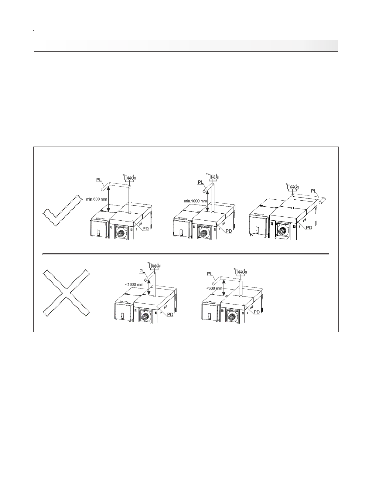
5.0. CONNECTION TO THE CENTRAL HEATING SYSTEM
All installation works must be made in accordance with valid national and European standards.
Boiler BioTec Plus can be built to closed and open central heating system. In both cases boiler
must be fired with wood logs or wood pellets. Installation has to be made in according to technical
standards, by a professional who will be responsible for proper boiler operation. The main flow
pipe from the boiler to the central heating system must not pass above the top back casing cover
(PD), otherwise the removal of the turbulators and cleaning of flue gas tubes is impossible (see
Figure 6). Before connecting boiler to central heating system, the system has to be flushed to
remove impurities remaining after system installation. It prevents boiler overheating, noise within
the system, disturbances at a pump and mixing valve. Boiler should always be connected to
central heating system by connectors, never by welding. Figure 1. shows minimum distances
required for boiler cleaning and maintenance.
Figure 6. Examples of main flow contructions
PD - Top back casing cover
PL - Main flow
Recommended Recommended
Technical instructions BioTec Plus
22
Page 23
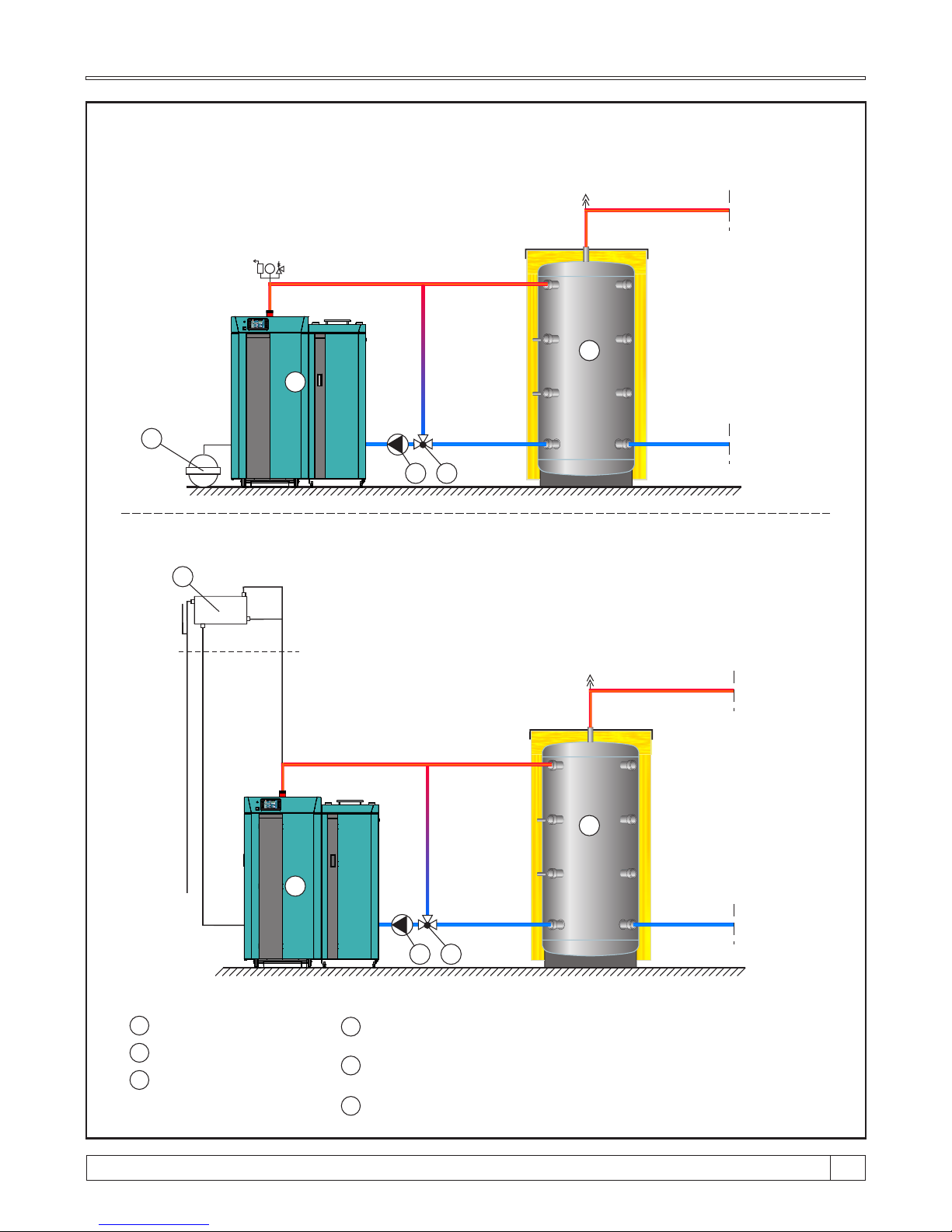
Scheme 1a. - Basic scheme for boiler instalation on closed central heating system with return flow
protection with thermic valve (group) (electrical connections and sensor are not
drawn, for details see general schemes)
bar
Scheme 1b. - Basic scheme for boiler instalation on open central heating system with return flow
protection with thermic valve (group) (electrical connecetions and sensors are not
drawn, for details see general schemes)
above the
highest heating
body
2
2
43
43
5
6
1 - Boiler BioTec Plus
2 - Accumulation tank «CAS»
3 - Boiler pump
4 - Return flow protection by 3-way mixing valve with actuator (protection
valve) or by 3-way thermic valve (like Esbe LTC, VTC..., 60°C)
5 - Expansion vessel for closed heating systems
(approx. 10% of the total volume of installation)
6 - Open expansion vessel for open heating systems (OPC)
(approx. 7% of total volume of installation)
BioTec Plus
05:08
OFF
0
0.0%
0.0%
xx°C
x%xx°C
xx°C
xx°C
xx°C
xx °C
25.0°C
20.0-0.0°C
20.0°C
-°C
xx°C
BioTec Plus
05:08
OFF
0
0.0%
0.0%
xx°C
x%xx°C
xx°C
xx°C
xx°C
xx °C
25.0°C
20.0-0.0°C
20.0°C
-°C
xx°C
15
23
Technical instructions BioTec Plus
1
1
Page 24

5.1. CONNECTION TO THE OPEN CENTRAL HEATING SYSTEM
If the boiler is aimed to be integrated into an open central heating system, one of possible way how
to connect the boiler to the system is shown on Scheme 1b. In case of BioTec Plus boilers, the
boiler pump obligatory has to be connected to the boiler control unit, in order to make turning on
and off of the pump depending on the temperature of the water in the boiler, to avoid boiler
condensation.
Connection to an open central heating system requires the implementation of an open expansion
vessel (OPC) above the level of the highest heating body (radiator). If the expansion vessel is
situated inside the non heated room, it has to be insulated. The volume of the open expansion
vessel is about 7% of the volume of entire heating installation. The boiler has to be connected with
one or more CAS water accumulators, depending on its nominal power. It is recommended to
connect minimum 50 liters water accumulation to each 1 kW boiler nominal power (i.e. for the 45
kW boiler minimal water accumulation should be 2250 liters) and always check the local
regulation about the needed minimum volume. The boiler should not be used without being
connected to the water accumulation tank with needed min. volume. It must be connected to the
CAS water accumulator obligatory through an 3-way mixing valve with actuator (protection valve)
or 3-way thermic valve (like ESBE VTC 512, VTC 531 (60°C), LTC 261, LTC 271 (60°C)).
5.2. CONNECTION TO THE CLOSED CENTRAL HEATING SYSTEM
In closed heating system (as in example shown in Scheme 1a) it is obligatory to build in certified
safety valve with opening pressure of 2,5 bar, minimum seat diameter of 15 mm, minimum inlet
connection of 1/2", minimum exit connection of 3/4" and a membrane expansion vessel. Safety
valve and expansion vessel must be built in accordance with professional rules and any valve
must not be located between safety valve and expansion vessel and boiler. The closed heating
system must have the installed expansion vessel of larger volume (vessel volume must be
approx. 10% of the heating installation volume). In all boiler types the heating pump must be
connected to boiler control unit so that the heating pump switching on and off would depend on
water temperature in the boiler.
The boiler has to be connected with one or more CAS water accumulators, depending of its
power. It is recommended to connect 50 liters water accumulation to each 1 kW boiler power (i.e.
for the 45 kW boiler minimal water accumulation should be 2250 liters). The functioning of boiler
control unit is shown in Technical manual ''Digital boiler control unit BioTec Plus''. The boiler
should not be used without being connected to the water accumulator. It must be connected to the
CAS water accumulator obligatory through an 3-way mixing valve with actuator (protection valve)
or 3-way thermic valve (like ESBE VTC 512, VTC 531 (60°C), LTC 261, LTC 271 (60°C)).
Technical instructions BioTec Plus
24
Page 25

5.2.1. BOILER THERMAL PROTECTION
According to European EN standards, boiler thermal protection must be installed in closed
heating system. Boiler is factory prepared for installation of thermal protection. Heat exchanger is
factory installed on left side of the boiler (wood), and thermal safety valve (7) should be installed
according to Scheme 2. On right side of the boiler (wood pellet) is also factory installed heat
exchanger with factory installed thermal safety valve. In case of any damage of boiler installed in
the closed heating system due to its overheating, and boiler or system are not equipped with any
thermal protection at all, or do not have properly installed thermal protection, guarantee will not be
applied.
IMPORTANT:
Thermal protection must be connected to the water supply installation of the premises supplied
from the public water supply line and not from hydrophor. Namely, in case of failure of power
supply, boiler could be overheated, and then hydrophor is not able to ensure required water
supply.
THERMAL PROTECTION:
Left side of the boiler (wood):
Thermal protection for left side of the boiler BioTec Plus consists of a heat exchanger which is
factory built in boiler, and thermal safety valve (7) (such as CALEFFI 543 513) (see Scheme 1).
Thermical valve (7) is installed into prepared connector (male thread 3/4") in the upper part of left
lateral side of the boiler casing.
Right side of the boiler (wood pellets):
Thermal protection for right side of the boiler BioTec Plus consists of a heat exchanger which
is factory built in boiler, and thermal safety valve (11) which is also factory built in boiler.
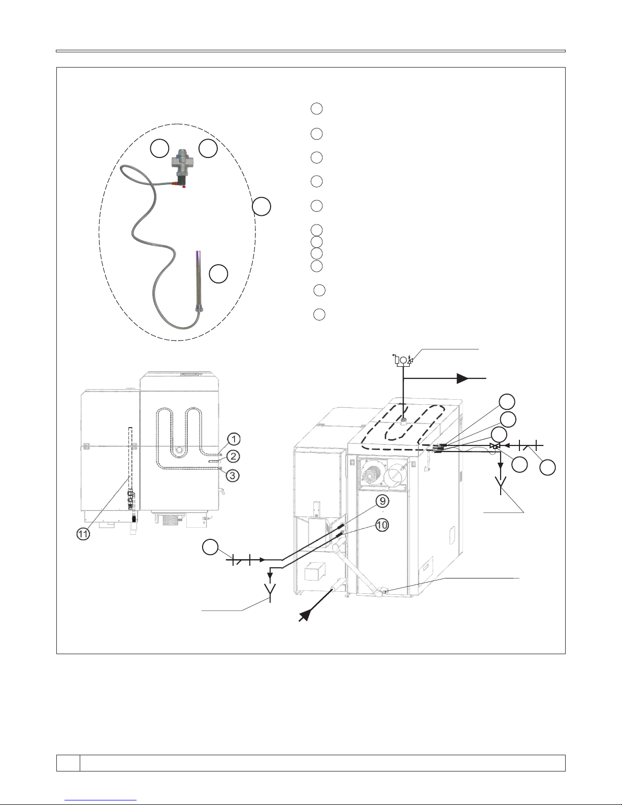
INSTALLATION (according to Scheme 2.):
Left side of the boiler (wood):
- screw the thermal safety valve sensor (6) (outer thread1/2") into the sleeve joint (2) (inner
thread1/2").
- fix the connection (4) (inner thread 3/4") of the thermal safety valve to the city plumbing cold
water inlet and the connection (5) (inner thread 3/4") to the connection point of the heat exchanger
(1) (outer thread1/2") - the arrow shows the direction.
- fix the tube connected to the sewage outlet at the connecting point (3) (outer thread1/2").
Right side of the boiler (wood pellets):
- fix the connection (9) (inner thread 3/4") to the city plumbing cold water inlet.
- fix the tube connected to the sewage outlet at the connecting point (10) (outer thread1/2").
15
25
Technical instructions BioTec Plus
Page 26
6
4
5
Scheme 2. - Thermal protection in an closed heating system
1 - Heat exchanger connection (to thermal safety valve)
(left side of the boiler - wood)
2 - Connection for the thermal safety valve sensor
(left side of the boiler - wood)
3 - Heat exchanger connection (to the sewerage)
(left side of the boiler - wood)
4 - Thermal safety valve connection
(cold water inlet HV)
5 - Thermal exchanger connection (to the boiler)
(to the boiler)
6 - Thermal safety valve-sensor
7 - Thermal safety valve
8 - Dirt filter (recommended)
9 - Heat exchanger connection
(right side of the boiler - wood pellet)
10 - Heat exchanger connection (to the sewerage)
(right side of the boiler - wood pellets)
11 - Factory inbuil thermal safety valve
(right side of the boiler - wood pellets)
7
bar
Safety air vent
group
Main flow
2
1
Sewerage
flow
7
3
8
Return flow
Filling / draining
Sewerage
flow
8
Technical instructions BioTec Plus
26
Page 27
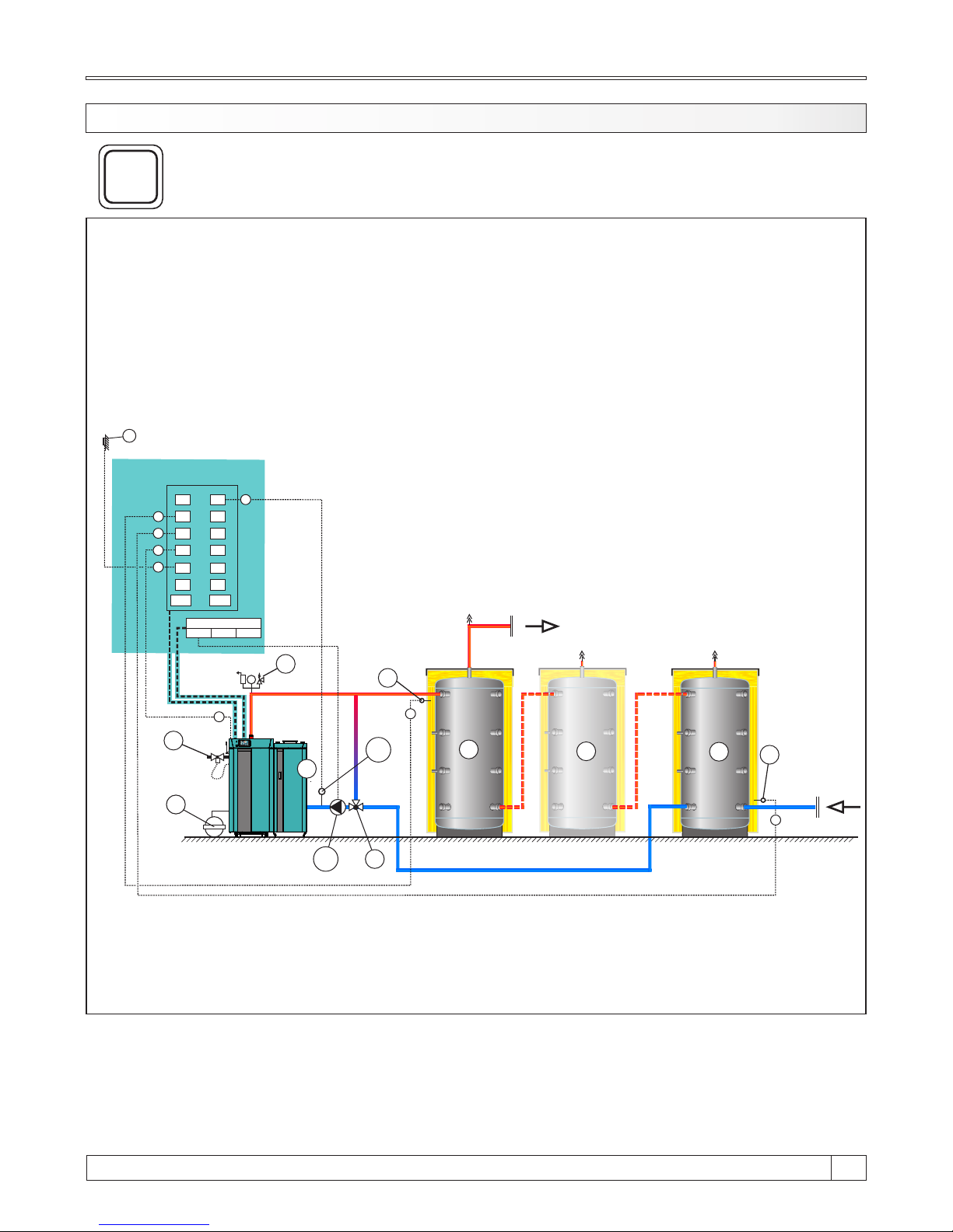
Scheme 3. - General scheme of closed central heating system with 2 or more accumulation tanks.
5.3. GENERAL CONNECTION SCHEMES
All general schemes hereafter will be shown with one accumulation tank, but they can be
performed with two or more accumulation tanks (buffer tanks).
Pay attention to electrical and sensors connections on general schemes!
bar
2
2
3
P1
6
4
5
B
A
2
D
S
1
S2
S3
S4
S5
S6
S7
S8
S9
S10
S
11
S12
S13 S14
Terminal Block
P1 P2
P3
B
A
D
Conn
e
cted t
o th
e boile
r
ele
ct
r
onics
A
B
E
E
1 - Boiler "BioTec Plus"
2 - "CAS" accumulation tank (buffer tank)
3 - Return flow protection (3-way mixing valve with actuator
(protection valve) or 3-way thermic valve (60°C),
VTC 512, VTC 531, LTC 261, LTC 271)
4 - Safety airvent unit
5 - Expansion vessel for closed systems (min. 10% of the total
volume of installation)
6 - Thermal safety valve
*
P1 - PumpP1 (boiler pump)
A - Accumulation tank sensor (upper)
B - Accumulation tank sensor (lower)
C - Return flow temperature sensor
D - Outer temperature sensor
E - Flue gas sensor
*
*
*
*
*
*
Not included in delivery of boiler BioTec Plus (need additional order)
BioTec Plus
05:08
OFF
0
0.0%
0.0%
xx°C
x%xx°C
xx°C
xx°C
xx°C
xx °C
25.0°C
20.0-0.0°C
20.0°C
-°C
xx°C
1
*
C
**
**
C
Can be used only if it’s on position „3” installed actuator
15
27
Technical instructions BioTec Plus
Each heating scheme with BioTec Plus has option of installing up to 4 pcs CM2K-B
modules (additional heating circuits management, DHW preparation and
recirculation).
i
Page 28
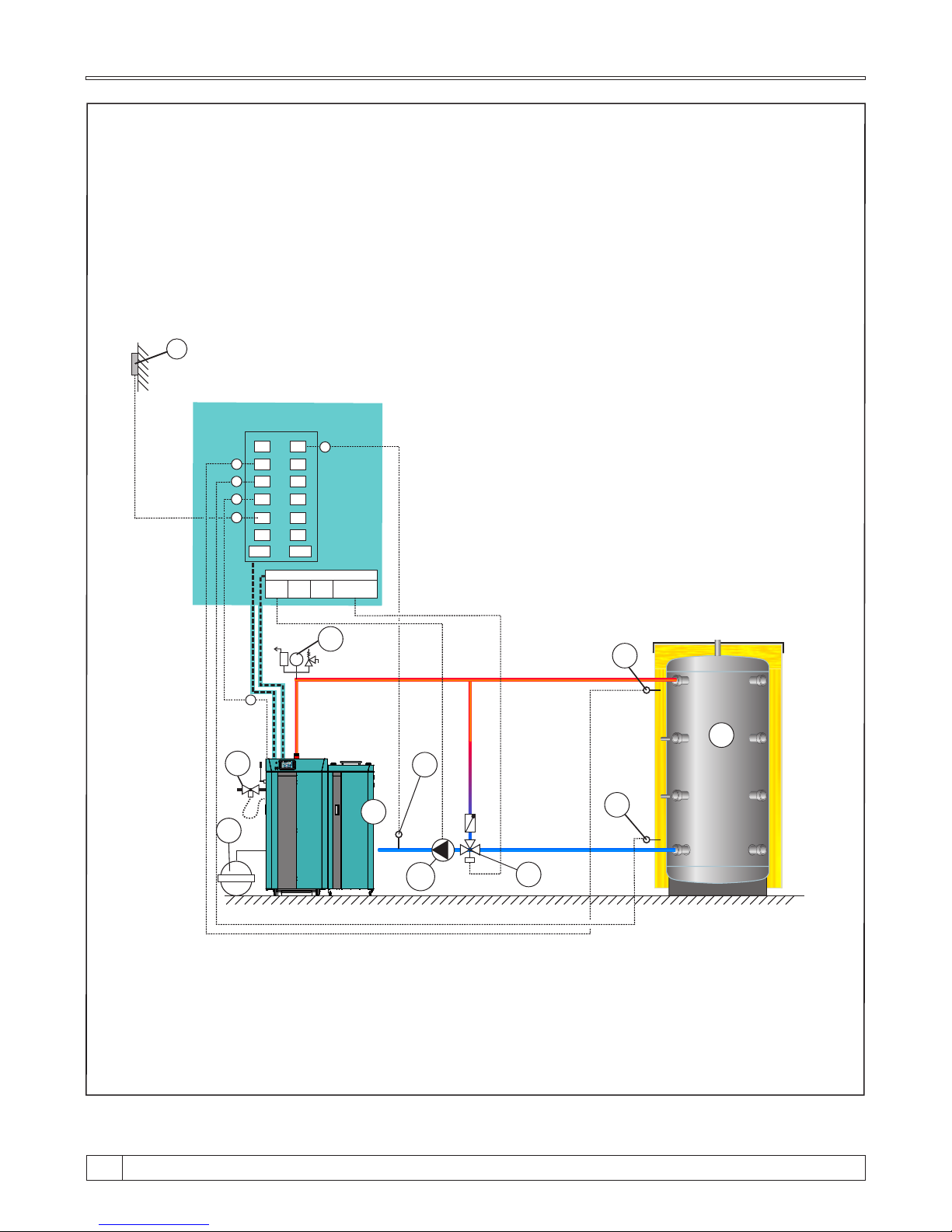
Scheme 4. - General scheme of closed central heating system with 1 accumulation tank, boiler
return flow protection with 3 - way mixing valve with electric actuator.
NOTE:
- According to this scheme is possible to preform version for open central heating system
(see point 6.0, Connection to the central heating system).
- Return flow protection (3) can be also performed by 3-way thermic valve ((60°C), VTC 512,
VTC 531, LTC 261, LTC 271).
D
S
1
S2
S3
S4
S5
S6
S7
S8
S9
S10
S
11
S12
S13 S14
Terminal Block
P1 P2
P3
D
bar
4
6
5
2
3
P1
A
B
C
B
A
E
E
C
*
Not included in delivery of boiler BioTec Plus (need additional order)
1 - Boiler "BioTec Plus".
2 - "CAS" accumulation tank (buffer tank).
3 - Return flow protection (3-way mixing valve with actuator
(protection valve)
4 - Expansion vessel for closed systems (min. 10% of the total
volume of installation)
5 - Safety airvent unit
6 - Thermal safety valve
*
*
*
*
P1 - Pump P1 (boiler pump)
A - Accumulation tank sensor (upper)
B - Accumulation tank sensor (lower)
C - Return flow temperature sensor
D - Outer temperature sensor
E - Flue gas sensor
*
C
on
n
ected t
o t
h
e boile
r
ele
ct
ron
ics
Mixing valve
actuator
BioTec Plus
05:08
OFF
0
0.0%
0.0%
xx°C
x%xx°C
xx°C
xx°C
xx°C
xx °C
25.0°C
20.0-0.0°C
20.0°C
-°C
xx°C
1
Technical instructions BioTec Plus
28
Page 29
bar
4
7
6
5
2
3P1
C
A
B
D
S
1
S2
S3
S4
S5
S6
S7
S8
S9
S10
S
11
S12
S13 S14
P1 P2
P3
D
C
A
E
E
F
B
Scheme 5.- General scheme of closed central heating system with 1 accumulation tank and
in front behin accumulation tankDHW preparation / d .
*
NAPOMENA:
- According to this scheme is possible to perform version for open central heating system
(see point 6.0, Connection to the central heating system).
P1 - Pump P1 (boiler pump)
P2 - Pump P2 (DHW pump)
P3 - 3-way diverter valve P3
A - Accumulation tank sensor (upper)
B - Accumulation tank sensor (lower)
C
-
DHW sensor (domestic hot water)
D - Outer temperature sensor
E - Flue gas sensor
F - Main flow sensor
J - Return flow temperature sensor
*
*
*
BioTec Plus
05:08
OFF
0
0.0%
0.0%
xx°C
x%xx°C
xx°C
xx°C
xx°C
xx °C
25.0°C
20.0-0.0°C
20.0°C
-°C
xx°C
1
J
J
IMPORTANT! This way of connecting DHW tank is neccesary if in some
part of the year we only want to use pellets for heat DHW tank.
P2
M
P
P3
1 - Boiler "BioTec Plus".
2 - "CAS" accumulation tank (buffer tank).
3 - Return flow protection (3-way mixing valve with actuator
4 - Expansion vessel for closed systems (min. 10% of the total
volume of installation)
5 - Sanitary water tank
(SKB-Digi/LKB-Digi/TB/STEB)
6 - Safety airvent unit
7 - Thermal safety valve
*
*
*
*
*
*
C
onnec
t
ed to th
e b
oil
er el
e
ctro
nics
Not included in delivery of boiler BioTec Plus (need additional order)
Terminal Block
Mixing valve
acturator
15
29
Technical instructions BioTec Plus
Page 30
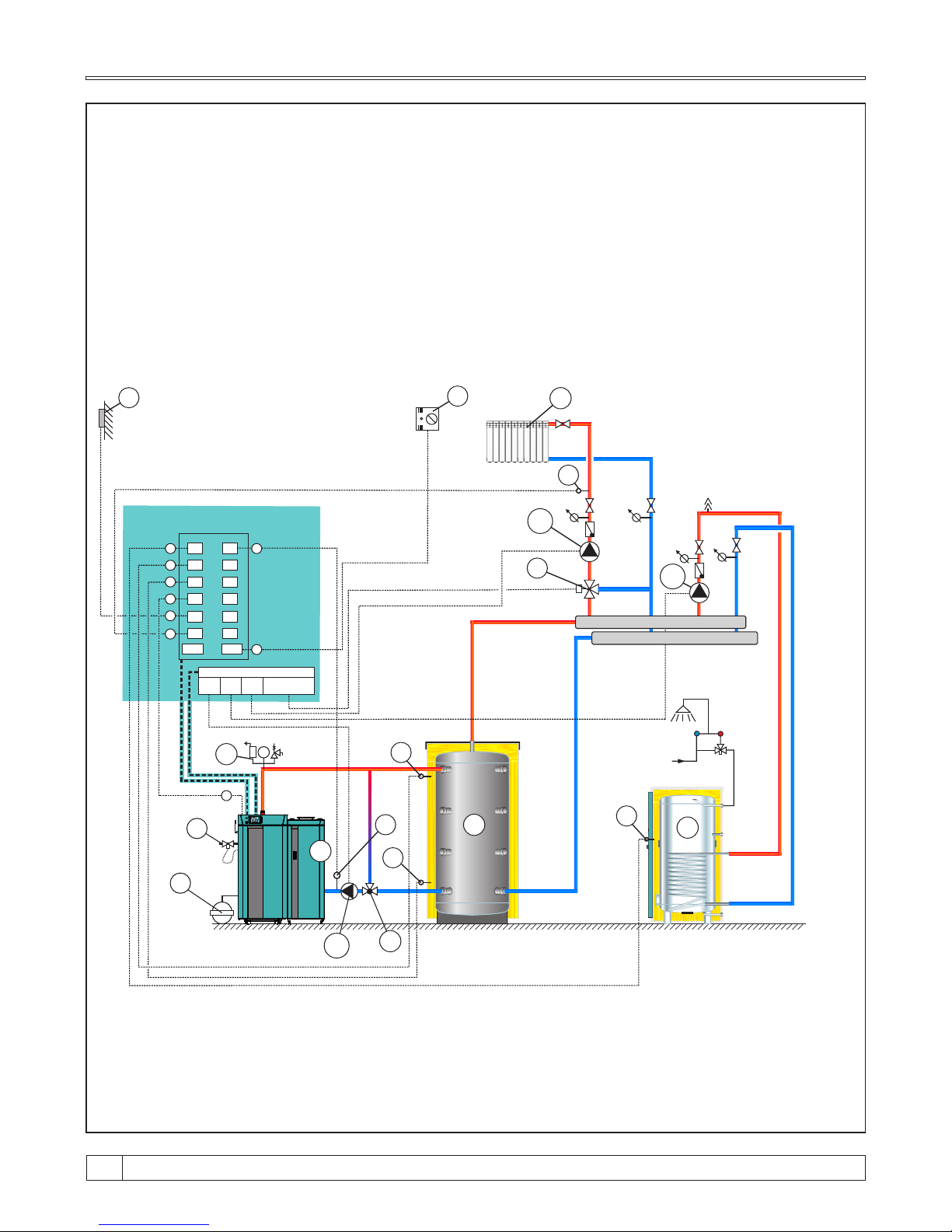
Scheme 6. - General scheme of closed central heating system with 1 accumulation tank,
heating system behind accumulation tank, 1 heating circuit with 3-way mixing valve
with actuator (or without actuator), and DHW preparation.
S
1
S2
S3
S4
S5
S6
S7
S8
S9
S10
S
11
S12
S13 S14
Terminal Block
P1 P2
P3
D
T
T
T T
G
P2
H
3
2
P1
4
I
bar
6
F
7
A
B
C
1 - Boiler "BioTec Plus".
2 - "CAS" accumulation tank (buffer tank).
3 - Return flow protection (3-way mixing valve with actuator
(protection valve) or 3-way thermic valve (60°C),
VTC 512, VTC 531, LTC 261, LTC 271)
4 - Expansion vessel for closed systems (min. 10% of the total
volume of installation)
5 - Sanitary water tank
(SKB-Digi/LKB-Digi/TB/STEB)
6 - Safety airvent unit
7 - Thermal safety valve
E
P1 - Pump P1 (boiler pump)
P2 - Pump P2 (DHW pump)
P3 - Pump P3 (heating pump)
A - Accumulation tank sensor (upper)
B - Accumulation tank sensor (lower)
C
-
DHW sensor (domestic hot water)
D - Outer temperature sensor
E - Flue gas sensor
F - Main flow sensor
G - 3-way mixing valve with actuator or manual
3-way mixing valve
H
- Room corrector (CSK)
I - Heating circuit
J - Return flow temperature sensor
*
A
B
C
Mixing valve
acturator
*
*
F
*
*
*
*
*
*
*
*
D
P3
5
E
*
H
Conn
e
cted t
o th
e boile
r
ele
ct
r
onics
Not included in delivery of boiler BioTec Plus (need additional order)
NOTE:
- According to this scheme is possible to preform version for open central heating system
(see point 6.0, Connection to the central heating system).
- Actuator can be installed only on position „G” or position „3” and noway on any other positions.
BioTec Plus
05:08
OFF
0
0.0%
0.0%
xx°C
x%xx°C
xx°C
xx°C
xx°C
xx °C
25.0°C
20.0-0.0°C
20.0°C
-°C
xx°C
1
**
**
Can be used only if it’s on position „G” installed actuator
J
J
***
***
Can be used only if it’s on position „3” installed actuator
Technical instructions BioTec Plus
30
Page 31
bar
4
7
6
5
2
3P1
P3
H
F
C
P2
A
B
D
S
1
S2
S3
S4
S5
S6
S7
S8
S9
S10
S
11
S12
S13 S14
Terminal Block
P1 P2
P3
Mixing valve
actuator
D
G
H
C
A
E
E
F
B
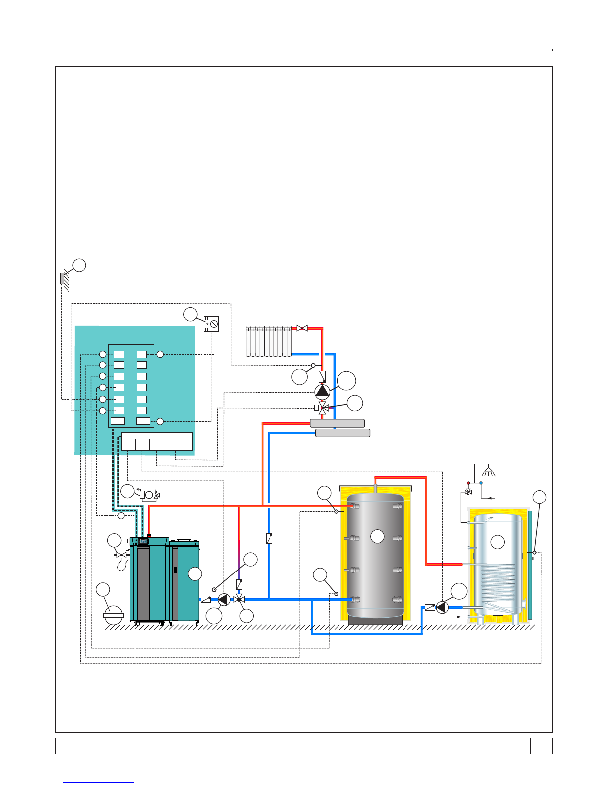
Scheme 7. - General scheme of closed central heating system with 1 accumulation tank, heating
system in front of accumulation tank, 1 heating circuit with 3-way mixing valve with
actuator, room corrector, and DHW preparing.
C
o
n
n
ecte
d t
o t
h
e bo
i
le
r
electron
ics
*
Not included in delivery of boiler BioTec Plus (need additional order)
NOTE:
According to this scheme is possible to preform version for open central heating system
(see point 6.0, Connection to the central heating system).
1 - Boiler "BioTec Plus ".
2 - "CAS" accumulation tank (buffer tank).
3 - Return flow protection
4 - Expansion vessel for closed systems (min. 10% of the total
volume of installation)
5 - Sanitary water tank
(SKB-Digi/LKB-Digi/TB/STEB)
6 - Safety airvent unit
7 - Thermal safety valve
*
*
*
*
*
*
P1 - Pump P1 (boiler pump)
P2 - Pump P2 (DHW pump)
P3 - Pump P3 (heating pump)
A - Accumulation tank sensor (upper)
B - Accumulation tank sensor (lower)
C
-
DHW sensor (domestic hot water)
D
-
Outer temperature sensor
E - Flue gas sensor
F - Main flow sensor
G - 3-way mixing valve with actuator
H
- Room corrector (CSK)
I - Heating circuit
J - Return flow temperature sensor
*
*
*
*
*
BioTec Plus
05:08
OFF
0
0.0%
0.0%
xx°C
x%xx°C
xx°C
xx°C
xx°C
xx °C
25.0°C
20.0-0.0°C
20.0°C
-°C
xx°C
1
J
J
**
**
Can be used only if it’s on position „3” installed actuator
15
31
Technical instructions BioTec Plus
Page 32
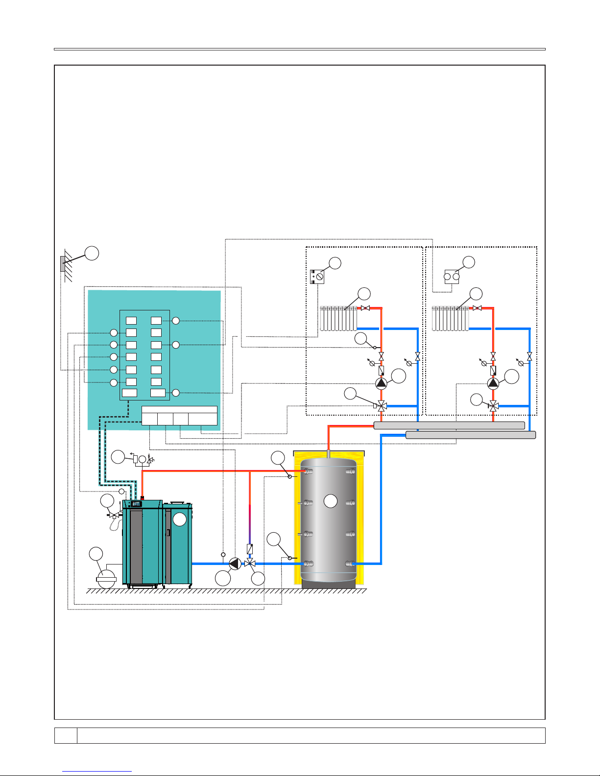
Scheme 8. - General scheme of closed central heating system with 1 accumulation tank,
heating system behind accumulation tank, 2 heating circuit with 3-way mixing valve
(one with actuator, other manually operated).
NOTE:
- According to this scheme is possible to preform version with heating system in front accumulation
tank.
- According to this scheme is possible to preform version for open central heating system
(see point 6.0, Connection to the central heating system).
- Actuator can be installed only on position „J” or position „3” and noway on any other positions.
D
S
1
S2
S3
S4
S5
S6
S7
S8
S9
S10
S
11
S12
S13 S14
Terminal Block
P1 P2
P3
D
bar
5
2
3
P1
A
B
B
A
E
E
T T
P3
J
H
I
F
T T
K
I
G
CIRCUIT 1 CIRCUIT 2
P2
F
H
G
Conn
e
cted t
o th
e b
oil
er
e
le
ct
r
o
nic
s
Mixing valve
actuator
1 - Boiler "BioTec Plus".
2 - "CAS" accumulation tank (buffer tank).
3 - Return flow protection (3-way mixing valve with actuator
(protection valve) or 3-way thermic valve (60°C),
VTC 512, VTC 531, LTC 261, LTC 271)
4 - Expansion vessel for closed systems (min. 10% of the total
volume of installation)
5 - Safety airvent unit
6 - Thermal safety valve
*
*
*
*
*
P1 - Pump P1 (boiler pump)
P2 - Pump P2 (heating pump circuit 2)
P3 - Pump P3 (heating pump circuit 1)
A - Accumulation tank sensor (upper)
B - Accumulation tank sensor (lower)
C - Return flow temperature sensor
D
-
Outer temperature sensor
E - Flue gas sensor
F - Main flow temperature sensor
G - Room thermostat
H
- Room corrector (CSK)
I - Heating circuit
J
-
3-way mixing valve with actuator or manual
3-way mixing valve
K -
Manual 3-way mixing valve
*
*
*
*
*
*
*
*
Not included in delivery of boiler BioTec Plus (need additional order)
BioTec Plus
05:08
OFF
0
0.0%
0.0%
xx°C
x%xx°C
xx°C
xx°C
xx°C
xx °C
25.0°C
20.0-0.0°C
20.0°C
-°C
xx°C
4
6
1
**
**
Can be used only if it’s on position „J” installed actuator
C
***
***
Can be used only if it’s on position „3” installed actuator
Technical instructions BioTec Plus
32
Page 33
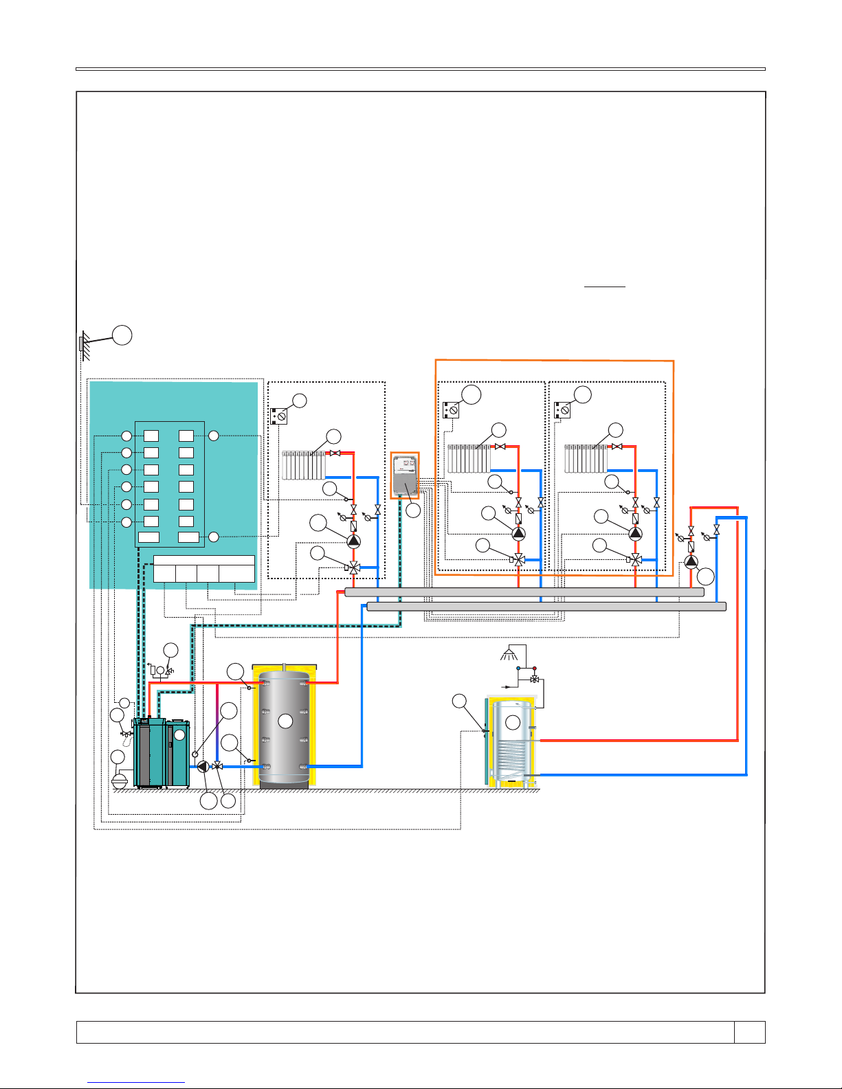
C
5
D
S
1
S2
S3
S4
S5
S6
S7
S8
S9
S10
S
11
S12
S13 S14
Terminal Block
P1 P2
P3
D
3
2
P1
bar
6
A
T TT T
K
K
G G
H1 H2
I I
J J
Managed with CM2K-B module
4
CM2K-B
7
F
B
T T
P3
G
H
I
L
CIRCUIT 1
A
B
E
E
H
L
C
T
T
P2
*
Not included in delivery of boiler BioTec Plus or CM2K-B module (need additional order)
Included in basic delivery of CM2K-B module
**
NOTE:
- According to this scheme is possible to preform version for open central heating system
(see point 6.0, Connection to the central heating system). It's possible to expand system of
heating circuit lead by CM2K-B module with installing additional CM2K-B modules (max. 3 pcs)
in serial connection.
- Actuator can be installed only on position „G” or position „3” and noway on any other positions.
1 - Boiler "BioTec Plus".
2 - "CAS" accumulation tank (buffer tank).
3 - Return flow protection (3-way mixing valve
with actuator (protection valve) or 3-way
thermic valve (60°C), VTC 512, VTC 531,
LTC 261, LTC 271)
4 - Expansion vessel for closed systems
(min. 10% of the total volume of
installation)
5 - Sanitary water tank
(SKB-Digi/LKB-Digi/TB/STEB)
6 - Safety airvent unit
7 - Thermal safety valve
*
*
*
*
*
*
*
F - CM2K -B module (can be expanded to
max. 4 units connected in series)
G - 3-way mixing valve with actuator
or manual 3-way mixing valve
H1 - Room corrector 2 (CSK)
H2 - Room corrector 3 (CSK)
I - Heating circuit
J - Main flow temperature sensor in
circuit CM2K.
(must be installed with
3-way mixing valve with actuator)
K - Heating pump (managed by CM2K-B)
L - Return flow temperature sensor
*
*
*
**
*
*
P1 - Pump P1 (boiler pump)
P2 - Pump P2 (DHW pump)
P3 - Pump P3 (heating pump circuit 1)
A - Accumulation tank sensor (upper)
B - Accumulation tank sensor (lower)
C - DHW sensor (domestic hot water)
D - Outer temperature sensor
E - Flue gas sensor
L - Main flow temperature sensor
H
- Room corrector 1 (CSK)
*
*
*
Scheme 9. - General scheme of closed central heating system with 1 accumulation tank, heating
system behind accumulation tank, 3 heating circuit with 3-way mixing valve and
DHW preparing.
*
C
on
nec
te
d t
o t
h
e bo
il
er
el
e
ct
ro
ni
cs
Mixing valve
actuator
BioTec Plus
05:08
OFF
0
0.0%
0.0%
xx°C
x%xx°C
xx°C
xx°C
xx°C
xx °C
25.0°C
20.0-0.0°C
20.0°C
-°C
xx°C
1
***
***
Can be used only if it’s on position „G” installed actuator
L
L
****
****
Can be used only if it’s on position „3” installed actuator
15
33
Technical instructions BioTec Plus
Page 34
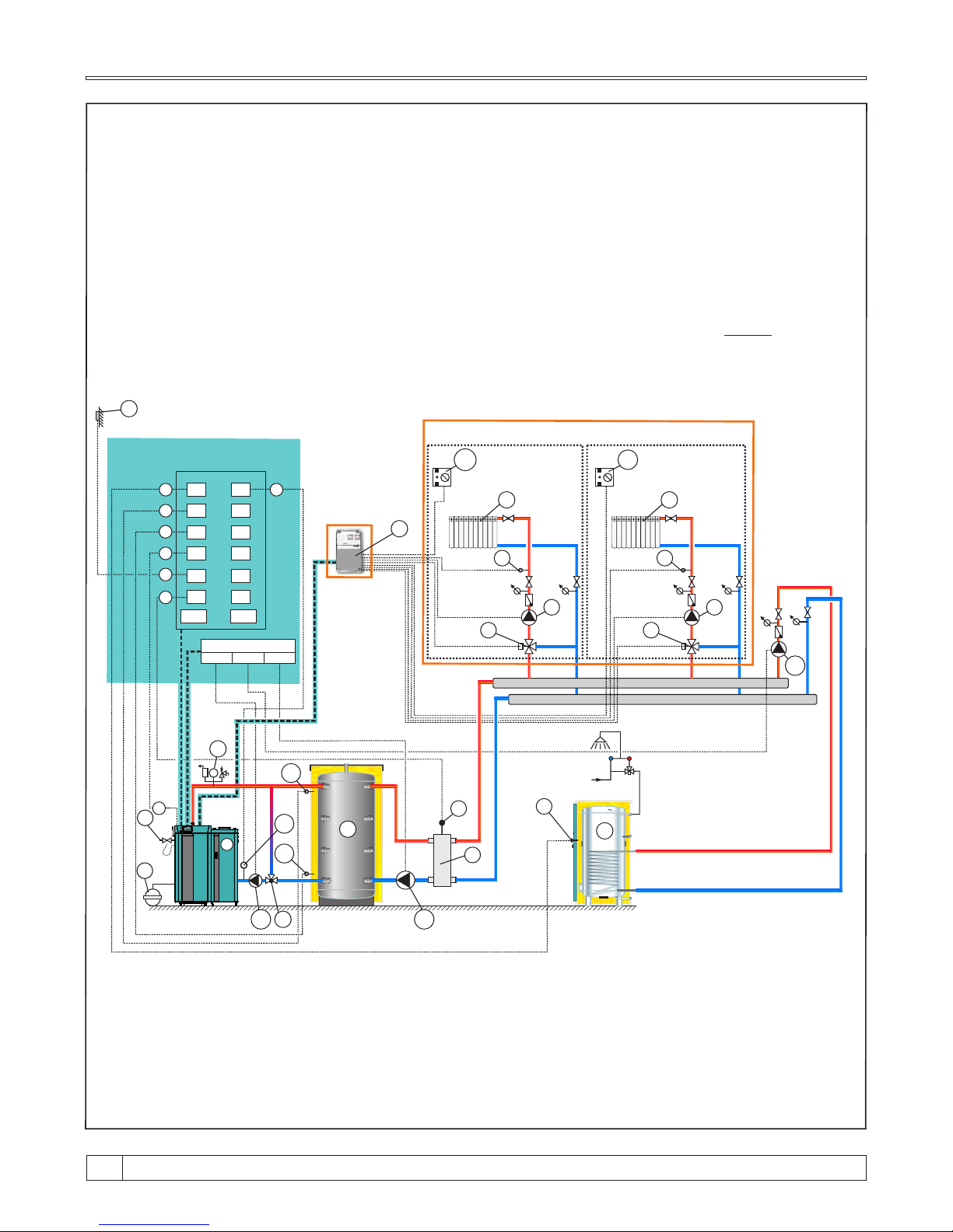
Sch
e
me 10. - G
eneral sc
h
e
m
e o
f c
l
osed ce
nt
ral heat
ing sys
t
e
m wi
t
h 1 ac
cumulati
on t
ank
, hyd
r
au
l
i
c
c
r
osso
ve
r b
e
h
i
n
d a
cc
u
m
u
l
a
t
ion ta
nk, 2 heat
i
ng circ
ui
t
s wi
th 3
-
way m
ixi
ng va
l
ve w
i
th
a
c
t
uato
r m
anage
d b
y C
M
2
K
-B mo
du
l
e, DH
W p
re
pari
ng.
*
F - CM2K -B module (can be expanded to
max. 4 units connected in series)
G - 3-way mixing valve with actuator
or manual 3-way mixing valve
H1 - Room corrector 1 (CSK)
(1x room corrector CSK included
in basic boiler delivery)
H2 - Room corrector 2 (CSK)
I - Heating circuit
J - Main flow temperature sensor in
circuit CM2K (must be installed with
3-way mixing valve with actuator)
K - Heating pump (managed by CM2K-B)
L - Return flow temperature sensor
*
*
**
*
T
T
3
2
P1
D
bar
6
A
C
T TT T
K K
G G
H1 H2
I I
J J
4
CM2K-B
M
8
S
1
S2
S3
S4
S5
S6
S7
S8
S9
S10
S
11
S12
S13 S14
Terminal Block
P1 P2
P3
7
F
5
B
B
A
C
D
M
P3
P2
*
*
E
E
*
Not included in delivery of boiler BioTec Plus or CM2K-B module (need additional order)
Included in basic delivery of CM2K-B module
**
NOTE:
- According to this scheme is possible to preform version for open central heating system
(see point 6.0, Connection to the central heating system).
- It's possible to expand system of heating circuit lead by CM2K-B module with installing additional
CM2K-B modules (max. 3 pcs) in serial connection.
Managed with CM2K-B module
Co
n
n
ec
ted t
o th
e bo
ile
r
e
le
ct
ron
i
c
s
P1 - Pump P1 (boiler pump)
P2 - Pump P2 (DHW pump)
P3 - Pump P3 (hydraulic crossover pump)
A - Accumulation tank sensor (upper)
B - Accumulation tank sensor (lower)
C - DHW sensor (domestic hot water)
D - Outer temperature sensor
E - Flue gas sensor
M - Hydraulic crossover sensor
(delivered as flow temperature sensor)
*
*
*
1 - Boiler "BioTec Plus".
2 - "CAS" accumulation tank (buffer tank).
3 - Return flow protection (3-way mixing valve
with actuator (protection valve) or
3-way thermic valve (60°C),
VTC 512, VTC 531, LTC 261, LTC 271)
4 - Expansion vessel for closed systems
(min. 10% of the total volume of
installation)
5 - Sanitary water tank
(SKB-Digi/LKB-Digi/TB/STEB)
6 - Safety airvent unit
7 - Thermal safety valve
8 - Hydraulic crossover
*
*
*
*
*
*
*
BioTec Plus
05:08
OFF
0
0.0%
0.0%
xx°C
x%xx°C
xx°C
xx°C
xx°C
xx °C
25.0°C
20.0-0.0°C
20.0°C
-°C
xx°C
1
L
***
Can be used only if it’s on position „3” installed actuator
***
L
Technical instructions BioTec Plus
34
Page 35
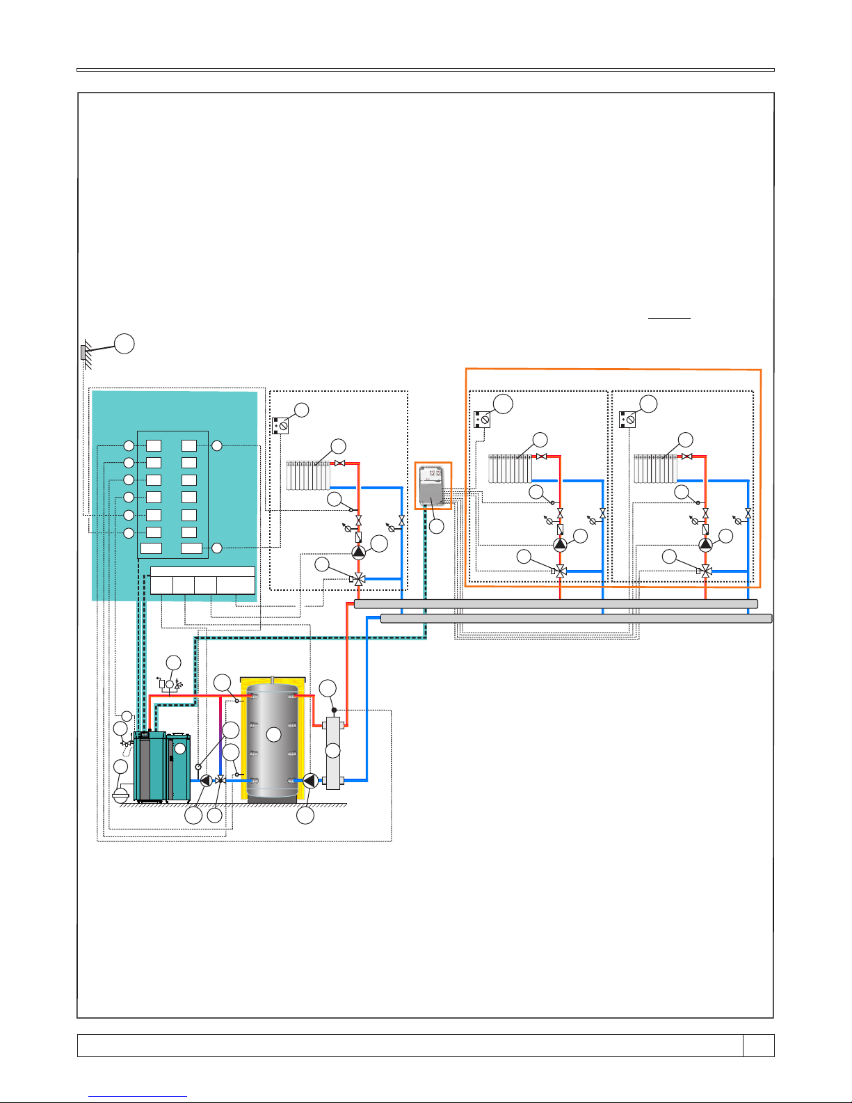
D
S
1
S2
S3
S4
S5
S6
S7
S8
S9
S10
S
11
S12
S13 S14
Terminal Block
P1 P2
P3
D
3
2
P1
bar
6
A
T TT T
K K
G G
H1 H2
I I
J J
4
CM2K-B
7
F
B
T T
P3
G
H
I
L
CIRCUIT 1
A
B
E
E
H
L
P2
M
5
M
*
Not included in delivery of boiler BioTec Plus or CM2K-B module (need additional order)
Included in basic delivery of CM2K-B module
**
NOTE:
- According to this scheme is possible to preform version for open central heating system
(see point 6.0, Connection to the central heating system).
- It's possible to expand system of heating circuit lead by CM2K-B module with installing additional
CM2K-B modules (max. 3 pcs) in serial connection.
- Actuator can be installed only on position „G” or position „3” and noway on any other positions.
C
on
ne
cte
d t
o t
he bo
il
er
el
ec
t
ro
ni
cs
Managed with CM2K-B module
1 - Boiler "BioTec Plus".
2 - "CAS" accumulation tank (buffer tank).
3 - Return flow protection (3-way mixing
valve with actuator (protection valve)
or 3-way thermic valve (60°C),
VTC 512, VTC 531, LTC 261, LTC 271)
4 - Expansion vessel for closed systems
(min. 10% of the total volume of
installation)
5 - Hydraulic crossover
6 - Safety airvent unit
7 - Thermal safety valve
*
*
*
*
*
*
P1 - Pump P1 (boiler pump)
P2 - Pump P2 (hydraulic crossover pump)
P3 - Pump P3 (heating circuit 1 pump)
A - Accumulation tank sensor (upper)
B - Accumulation tank sensor (lower)
C - Return flow temperature sensor
D - Outer temperature sensor
E - Flue gas sensor
H -
Room corrector 1 (CSK)
L - Main flow temperature sensor (circuit 1)
M - Hydraulic crossover sensor
(delivered as flow temperature sensor)
*
*
*
*
F - CM2K -B module (can be expanded to
max. 4 units connected in series)
G - 3-way mixing valve with actuator
or manual 3-way mixing valve
H1 - Room corrector 2 (CSK)
(1x room corrector CSK included
in basic boiler delivery)
H2 - Room corrector 3 (CSK)
I - Heating circuit
J - Main flow temperature sensor in
circuit CM2K (must be installed with
3-way mixing valve with actuator)
K - Heating pump (managed by CM2K-B)
*
*
**
*
*
*
Mixing valve
actuator
Sche
m
e 1
1. - G
eneral sch
eme o
f close
d centr
al hea
t
ing s
yst
em with 1 a
c
c
umulat
i
on ta
n
k
, h
yd
r
a
u
l
i
c
cr
ossover behind accum
ul
at
io
n tank, 3 hea
t
ing c
ircu
its w
ith 3
-
w
ay m
ixing valve with
a
ctuat
or (
1 di
r
ect he
a
t
in
g ci
rcuit an
d 2 c
i
r
c
uit
s mana
g
e
d b
y C
M
2
K-B mo
d
u
l
e).
BioTec Plus
05:08
OFF
0
0.0%
0.0%
xx°C
x%xx°C
xx°C
xx°C
xx°C
xx °C
25.0°C
20.0-0.0°C
20.0°C
-°C
xx°C
1
**
***
Can be used only if it’s on position „G” installed actuator
C
****
****
Can be used only if it’s on position „3” installed actuator
C
15
35
Technical instructions BioTec Plus
Page 36
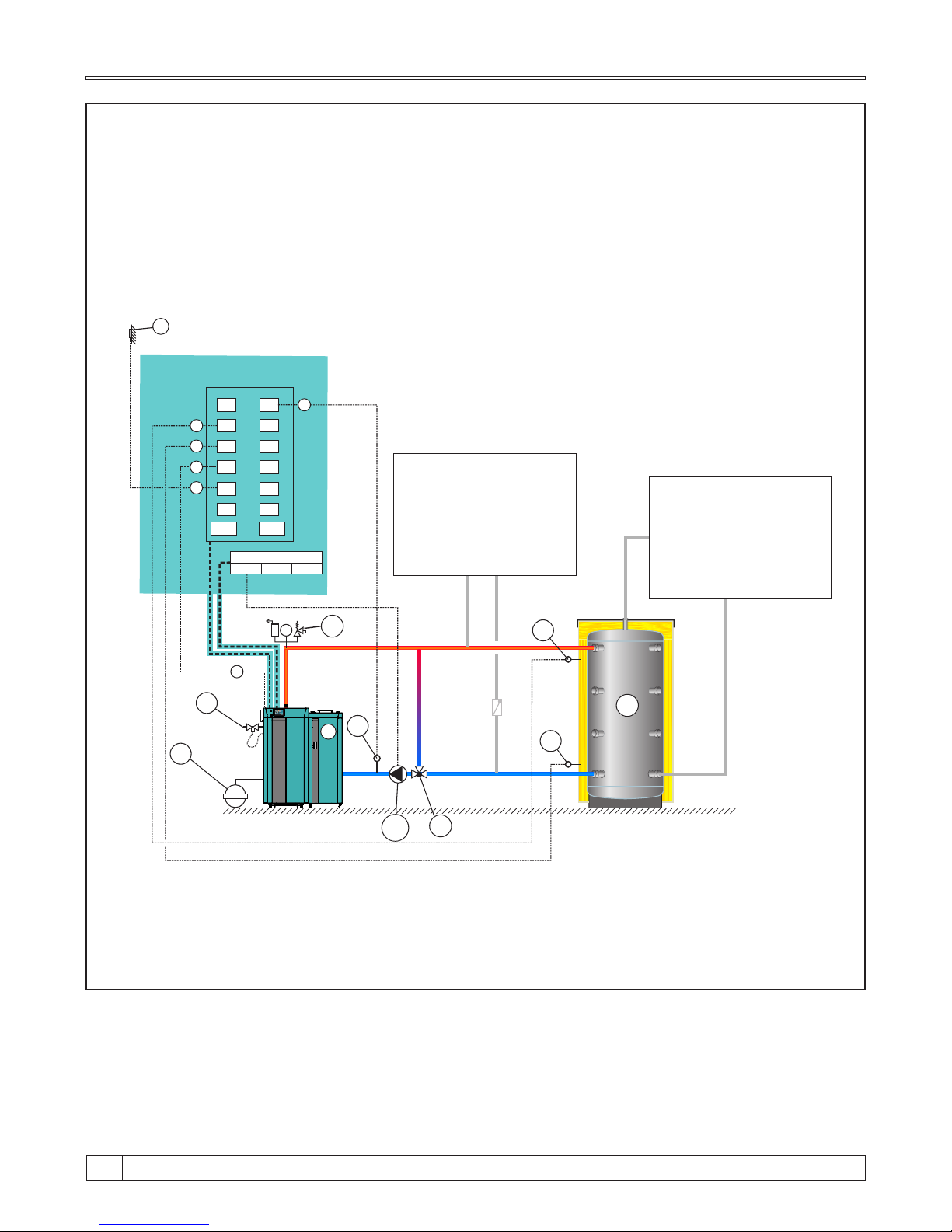
Scheme 12. - General scheme of closed central heating system with 1 accumulation tank,
custom heating system
D
S
1
S2
S3
S4
S5
S6
S7
S8
S9
S10
S
11
S12
S13 S14
Terminal Block
P1 P2
P3
D
E
E
3
2
P1
6
bar
4
5
A
NOTE:
- According to this scheme is possible to preform version for open central heating system
(see point 6.0, Connection to the central heating system).
A
B
B
1 - Boiler "BioTec Plus".
2 - "CAS" accumulation tank (buffer tank).
3 - Return flow protection (3-way mixing valve with actuator
(protection valve) or 3-way thermic valve (60°C),
VTC 512, VTC 531, LTC 261, LTC 271)
4 - Expansion vessel for closed systems (min. 10% of the total
volume of installation)
5 - Safety airvent unit
6 - Thermal safety valve
*
*
*
*
*
P1 - Pump P1 (boiler pump)
A - Accumulation tank sensor (upper)
B - Accumulation tank sensor (lower)
C - Return flow temperature sensor
D - Outer temperature sensor
E - Flue gas sensor
*
Co
n
n
ect
ed t
o th
e b
o
i
le
r
e
le
c
t
r
on
i
c
s
Custom heating system
(only with 3-way mixing
valve with actuator) -
heating system in front
accumulation tank
Custom heating system -
heating system behind
accumulation tank
*
Not included in delivery of boiler BioTec Plus (need additional order)
BioTec Plus
05:08
OFF
0
0.0%
0.0%
xx°C
x%xx°C
xx°C
xx°C
xx°C
xx °C
25.0°C
20.0-0.0°C
20.0°C
-°C
xx°C
1
C
C
**
**
Can be used only if it’s on position „3” installed actuator
Technical instructions BioTec Plus
36
Page 37
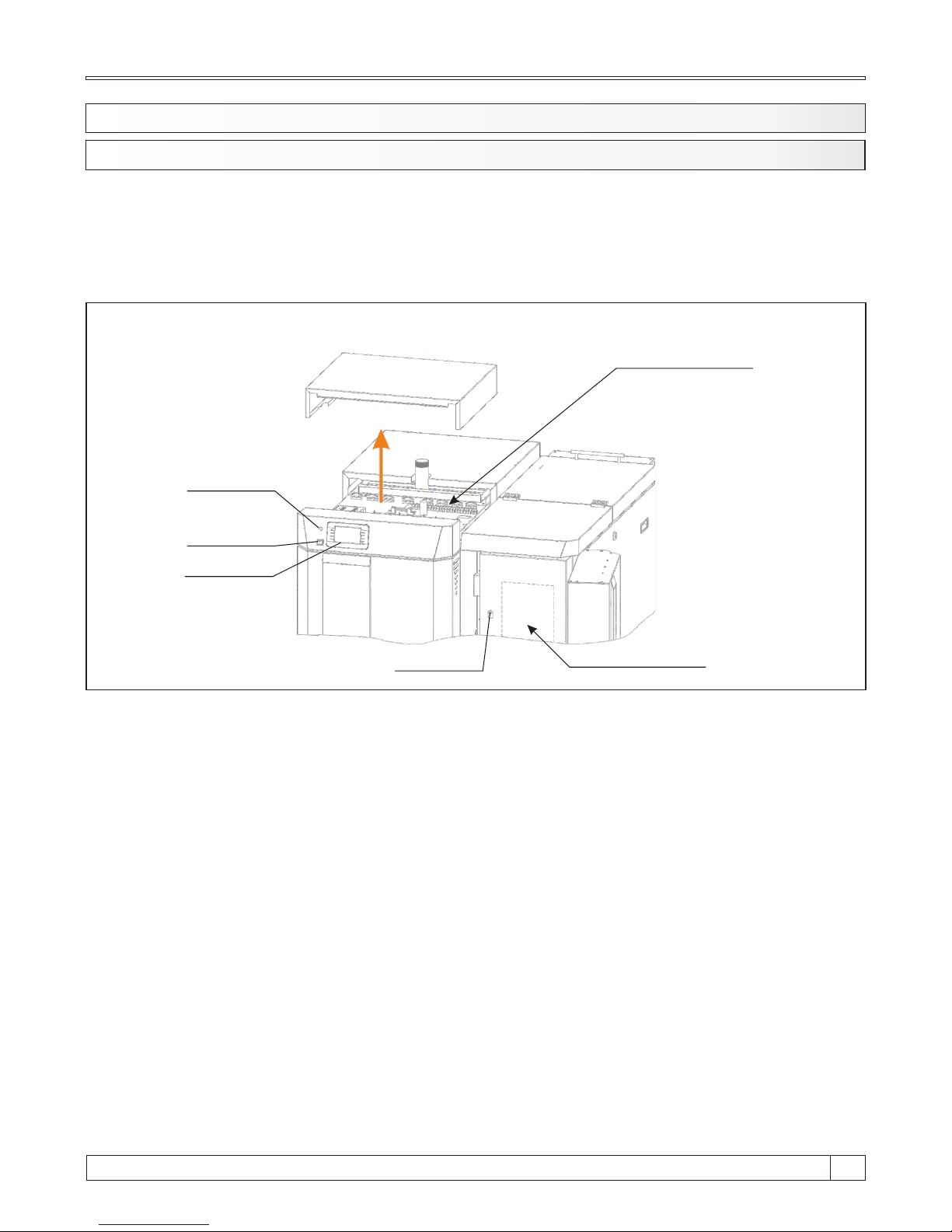
6.1. BOILER CONTROL
The boiler is controlled with electronic control unit, built in the upper part of the boiler, below upper
casing.
Control unit controls boiler functioning, one heat circuit through 3 way mixing valve with actuator
and outer temp. sensor and DHW tank. On the front boiler panel are main switch, for switching
on/off the boiler control unit, safety thermostat and touch screen of control unit.
6.0. BOILER REGULATION
Figure 7. Boiler electronic
Boiler electronic
position
Control unit
display
Main switch
STB Safety
thermostat
STB Safety
thermostat
Boiler electronic
position
15
37
Technical instructions BioTec Plus
Page 38
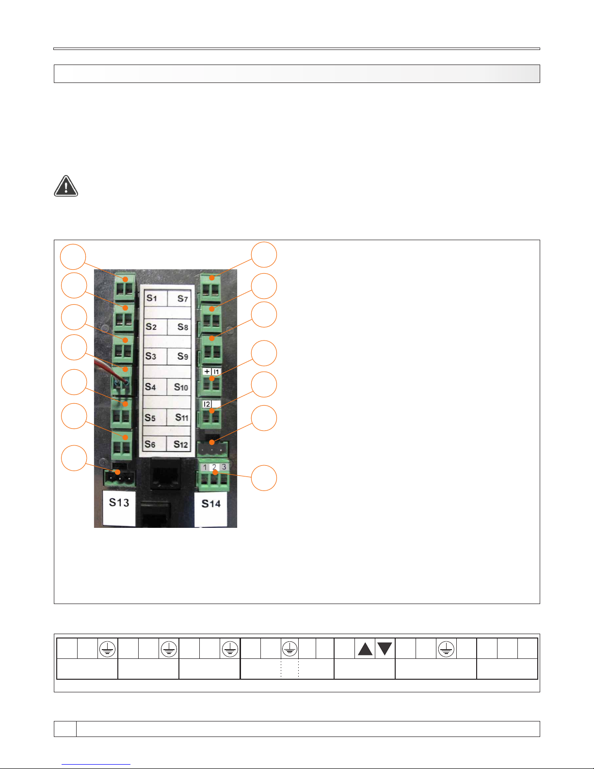
CAUTION:
When connecting any electrical part be sure to unplug the boiler at the main switch and
disconnect the power supply.
S1
S2
S3
S4
S5
S6
S13
S7
S8
S9
S10
S11
S12
S14
S1 - Sanitary water / hydraulic crossover sensor*
S2 - Accumulation tank 1 sensor (up)
S3 - Accumulation tank 2 sensor (down)
S4 - Flue gas sensor
S5 - Outer sensor
S6 - Main flow sensor / hydraulic crossover sensor*
S7 - Return flow sensor
S8 - Not used
S9 - Room thermostat
S10 - Alarm output 1 (Additional equipment)
S11 - Alarm output 2 (Additional equipment)
S12 - Not used
S13 - Not used
S14 - Room corrector
Terminal Block & Strip Connector
7.0. ELECTRIC CONNECTION
All electrical works must be performed by a certified professional in accordance with valid national
and European standards.
A device for switching of all power supply poles must be installed in electrical installation in
accordance with the national regulations on electrical installations.
*If the configuration contains hydraulic crossover, delivered main flow temperature sensor or
sanitary water sensor becomes hydraulic crossover sensor, depending on other elements of the
configuration. When configuration contains hydraulic crossover along DHW tank or heating circuit,
then hydraulic crossover temp. sensor must be connected to connector S6, in other cases hydraulic
crossover temp. sensor must be connected to the connector S1.
N L N L N L N L L
N N L
L1
N
MD
Red
Black
White
Power supply
230 V
Pump P1
Pump P2
Pump
P3
Mixing valve
actuator
Fan
RPM
Counter
Technical instructions BioTec Plus
38
Page 39
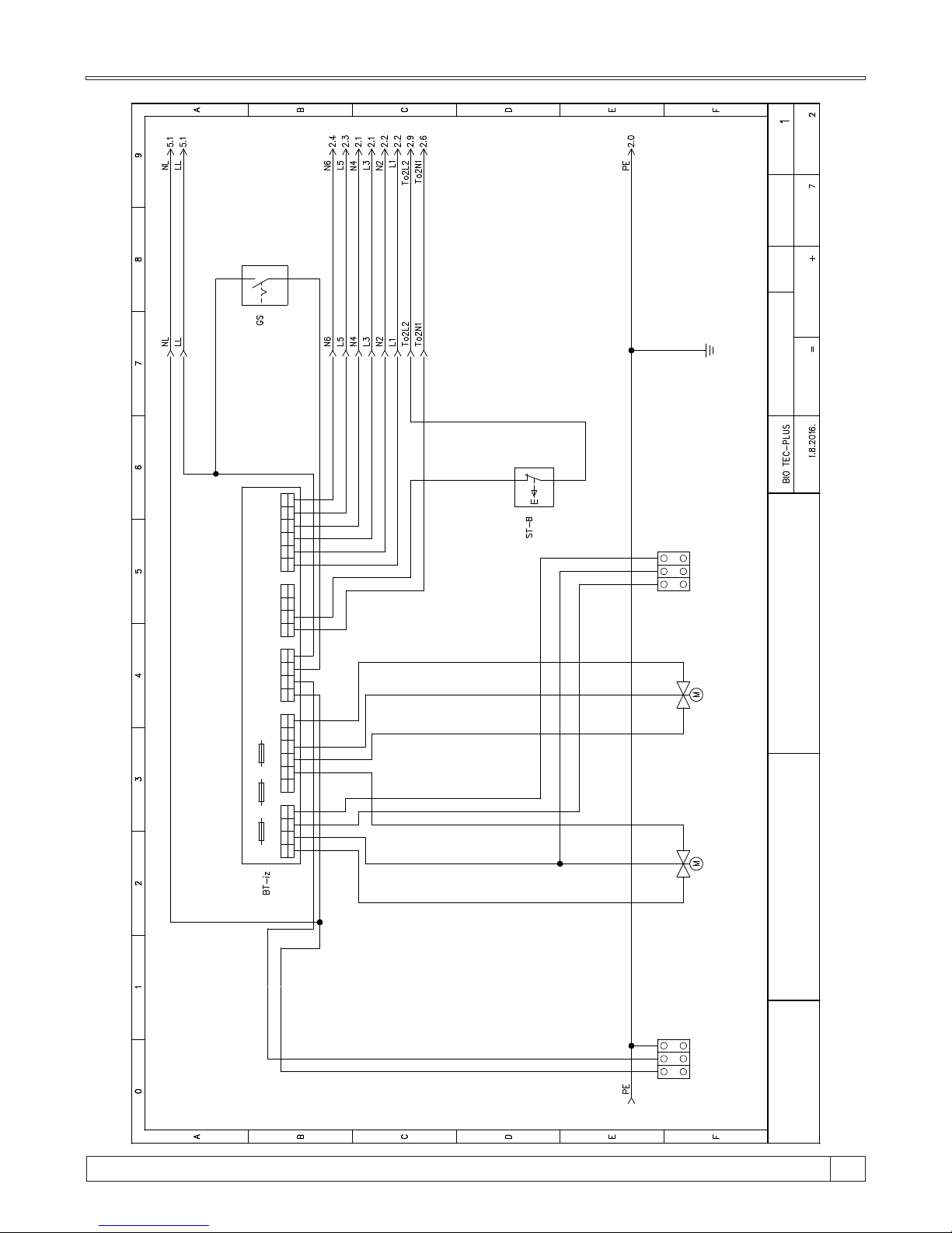
1 2 3 4
T O 4
1 2 2 21 13 3 34 4 45 56 6
T O 1 T O 2 T O 3
1 2 3 4
P OW 1
L LL t L t L t L t L t L t L t L t L t L t L tN N N N N N N N NL p Lp
BI O T E C - OUTPUTS
F1 - 3 ,15 A F 2 - 5 00 m A F 3 - 3,1 5A
ELECTRIC SCHEME - BOILER CONTROL UNIT
BioTec Plus
N L P E N O Z
Supply
230V
Secondary air
motor device
Primary air
motor device
Mixing valve
motor device
Project:
Date:
Drawing n.:
Function: Lacation:
Init.:
Rev.:
Total pages:
Page:
Next page:
15
39
Technical instructions BioTec Plus
Page 40
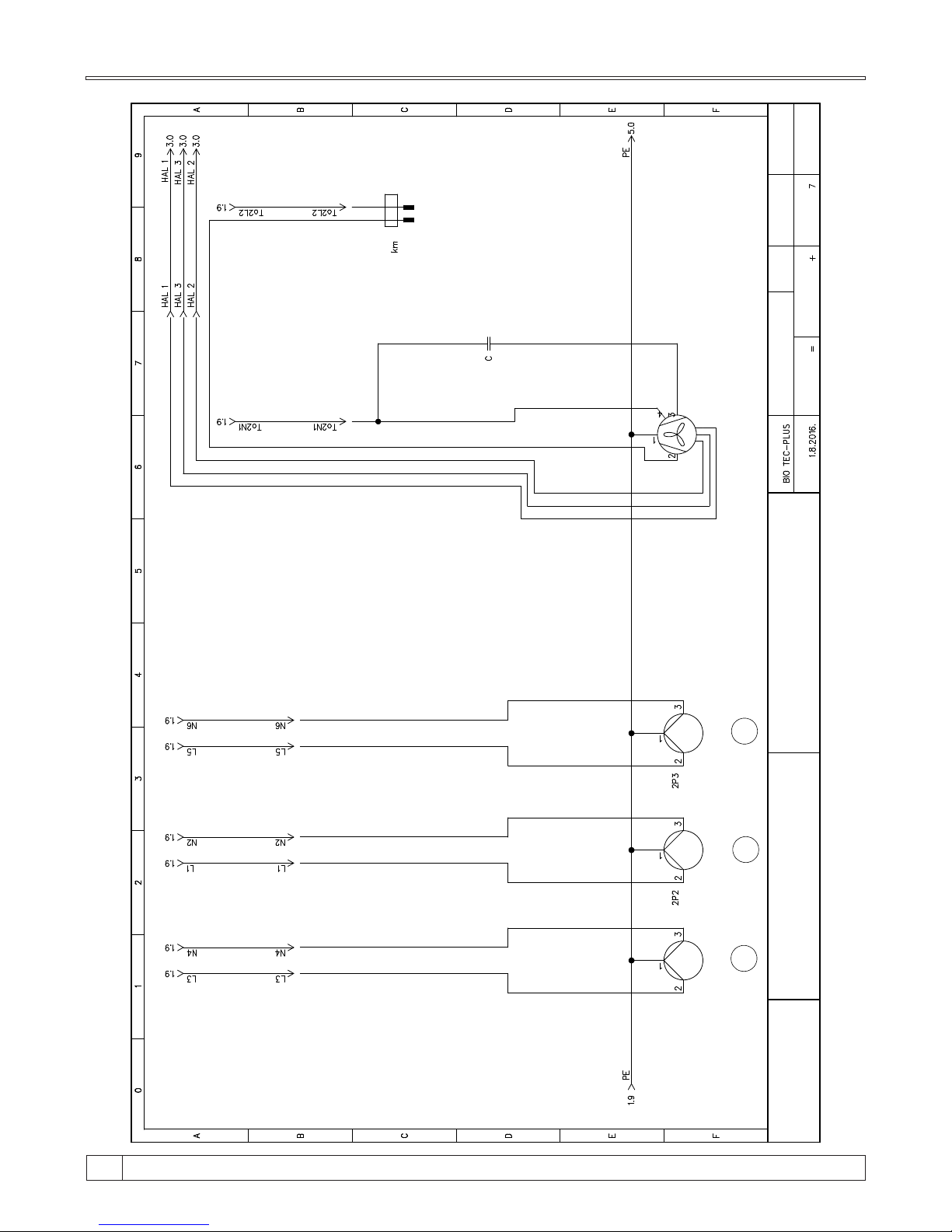
Red
Black
White
Black
Blue
Brown
P1
P 2
P 3
2 1
2P C RNI
MUŠK I
ELECTRIC SCHEME - BOILER CONTROL UNIT
BioTec Plus
Project:
Date:
Drawing n.:
Function: Lacation:
Init.:
Rev.:
Total pages:
Page:
Next page:
2
3
Heating
pump
Heating
pump
Buffer tank
pump
Flue gas fan with
RPM counter
Technical instructions BioTec Plus
40
Page 41
1
1 1 1
1
2
2 2 2
2
3
3 3
3
4 4
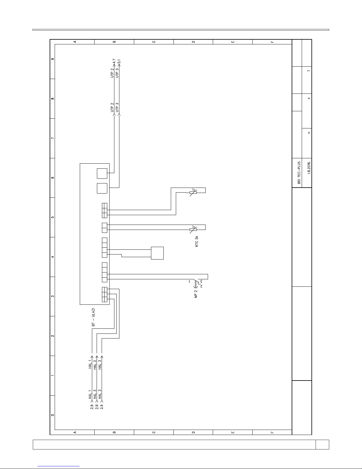
H AL 1 A i 2 A i 3 A i 1 T C 1
UT P 1 U TP 2
+5 V
SI G GND
GND
ELECTRIC SCHEME - BOILER CONTROL UNIT
BioTec Plus
Project:
Date:
Drawing n.:
Function: Lacation:
Init.:
Rev.:
Total pages:
Page:
Next page:
3
4
Boiler door
microswitch
Boiler sensor Thermocouple
Coded key
for boiler
power
15
41
Technical instructions BioTec Plus
Page 42
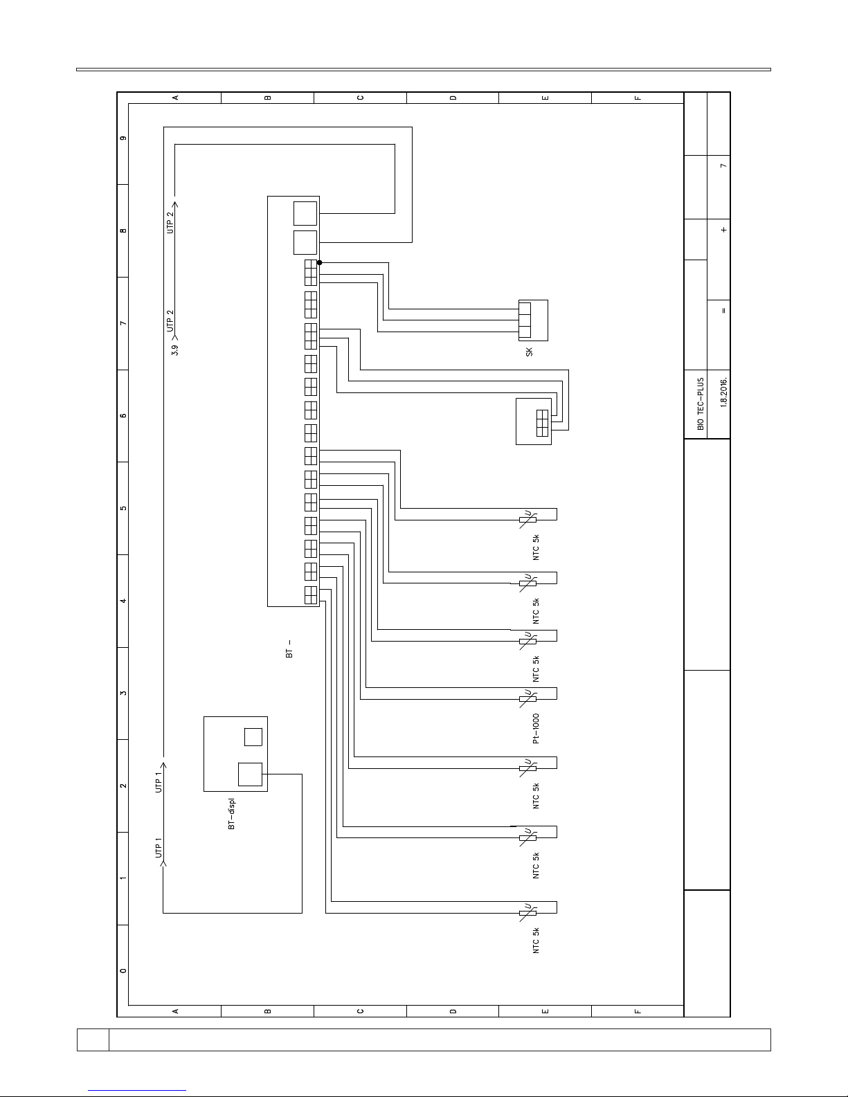
UT P
US B
BI O T E C - di sp l
U TP CABLE
UT P CABLE
1 2
SIG
GND
1 2
SIG
GND
1 2
SIG
GND
1 2
SIG
GND
1 2
SIG
GND
1 2
SIG
GND
1 2
SIG
GND
1 2
SIG
GND
1 2
SIG
GND
1 2
SIG
GND
1 2
SIG
GND
1 2
SIG
GND
1 2
+5V
3
GND
SIG
S1 S 2 S3 S 4 S5 S 6 S7 S8 S 9 S 10 S11 S12
U TP 1 UT P 2
BI O T E C - SENSORS
1 2
+5 V
3
GND
SIG
S13
1 2
+5 V
3
GND
SIG
S14
1 2 3
S K
U TP CABLE
3 2
+5V
1
GND
SIG
FUEL LEVEL SENSOR
ELECTRIC SCHEME - BOILER CONTROL UNIT
BioTec Plus
Project:
Date:
Drawing n.:
Function: Lacation:
Init.:
Rev.:
Total pages:
Page:
Next page:
4
5
DHW sensor
S 9 - room thermostat
S10 - output for alarms
S11 - output for alarms
Buffer
tank sensor
1
Buffer
tank sensor
2
Flue gas
sensor
Outer
sensor
Boiler flow
sensor
Boiler
return sensor
Room corrector
SENSORS
Technical instructions BioTec Plus
42
Page 43
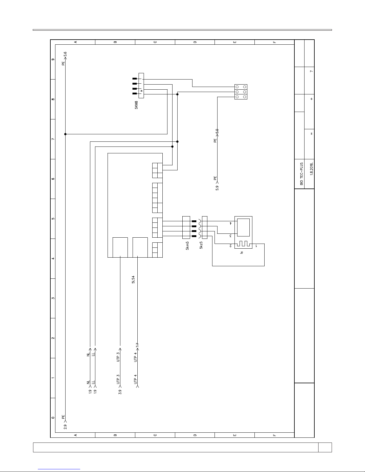
RS 4 85
A
B G
LA MB D A PROBE
H
H
L -
L+
T fg . S
1
2
DI / AO
G
S T
O
Sf
N F
DI
23 0 V
UT P 2
UT P 1
1
1
8
8
»
H
H
+
_
WHITE
WHITE
GREY
BLACK
U TP CABEL
U TP CABEL
4P C RNI
MUŠK I
L1N L2
PE N L
ELECTRIC SCHEME - BOILER CONTROL UNIT
BioTec Plus
Project:
Date:
Drawing n.:
Function: Lacation:
Init.:
Rev.:
Total pages:
Page:
Next page:
5
6
Lambda
probe
Feeding
system motor
device
15
43
Technical instructions BioTec Plus
Page 44
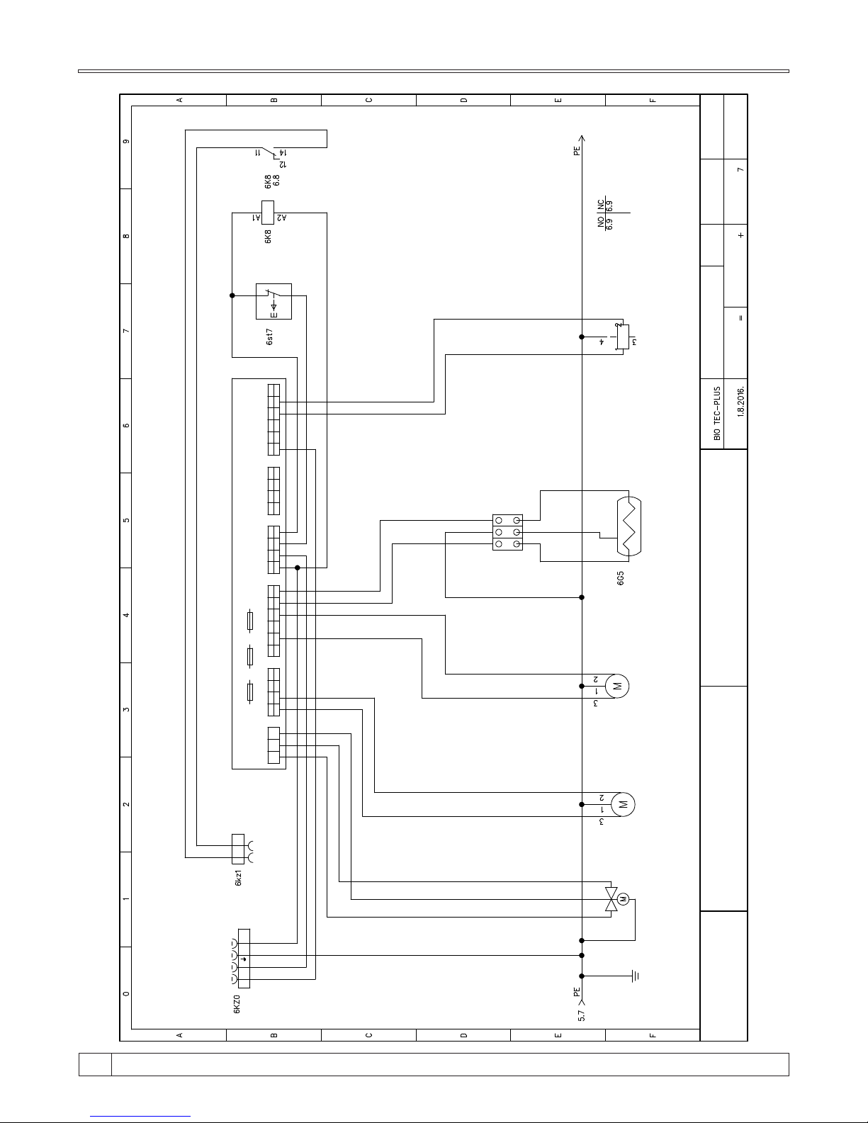
F1 - 3 ,15 A F 2 - 5 00 m A F3 - 3 ,15 A
1 2 3 4
T O 4
1 2 2 21 13 3 34 4 45 56 6
T O 1 T O 2 T O 3
1 2 3 4
P OW 1
L LL t L t L t L t Lt L t L t L t L t L t L tN N N N N N N N NL p L p
PE L TE C -
1 2 3
L t NL t
T O 5
4P C RNI
ŽEN SK I
L1 NL2
2P C RNI
ŽENS K I
2 1
ELECTRIC SCHEME - BOILER CONTROL UNIT
BioTec Plus
Project:
Date:
Drawing n.:
Function: Lacation:
Init.:
Rev.:
Total pages:
Page:
Next page:
6
7
Motor for
grate cleaning
Feeder screw
motor device
RSE rotation valve
motor device
Electric heater
Electric magnet
Technical instructions BioTec Plus
44
Page 45
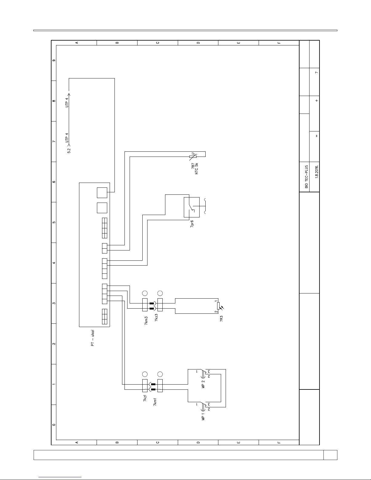
1
1 1 1
1
2
2 2 2
2
3
3 3
3
4 4
4
H AL 1 A i 2 A i 3 A i 1 R o 1
UT P 1 U TP 2
PE L TE C - ul a zi
+5 V
SI G GND
+12 V REL 1 REL 2
GND
2P C RNI
ŽENS K I
2 1
2 1
2P CR NI
MUŠK I
1
1
2 1
2P SI V I
MUŠK I
2P SI V I
ŽEN SK I
2 1
2
2
1
2
3
ELECTRIC SCHEME - BOILER CONTROL UNIT
BioTec Plus
Project:
Date:
Drawing n.:
Function: Lacation:
Init.:
Rev.:
Total pages:
Page:
Next page:
7
Grate
microswitch
Photocell
Pressure switch
Boiler sensor
15
45
Technical instructions BioTec Plus
Page 46
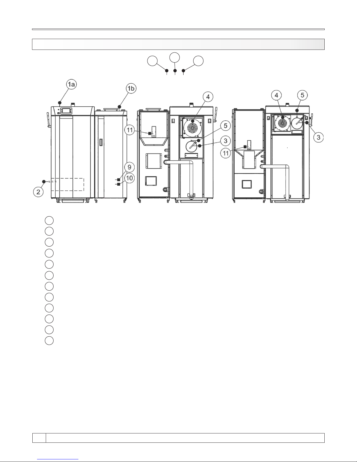
7.1. BOILER SENSORS AND PROBES
6 8
7
*
*
1a
1b
2
3
4
5
6
7
8
- Boiler temperature sensor (NTC 5K) (left side of the boiler; fuel: wood)
- Boiler temperature sensor (NTC 5K) (right side of the boiler; fuel: wood pellets)
- Combustion chamber temperature sensor (thermo couple)
- Flue gas sensor (PT1000)
- Fan RPM sensor
- Lambda probe
- Outer temperature sensor (NTC 5K)
- Main / return flow temperature sensor (NTC 5K)
- Domestic hot water (DHW) temperature sensor (NTC 5K)
- Pressure switch
- Photocell
- Fuel level sensor (wood pellets)
* - Installed on heating installation
9
10
11
Technical instructions BioTec Plus
46
Page 47

Temperature
(°C)
Resis.
( W )
Temperature
(°C)
Resis.
( W )
-30
885 225 1.866
-25 904 230 1.886
-20 923 235 1.905
-15 942 240 1.924
-10 962 245 1.943
-5 981 250 1.963
0 1.000 255 1.982
5 1.019 260 2.001
10 1.039 265 2.020
15 1.058 270 2.040
20 1.077 275 2.059
25 1.096 280 2.078
30 1.116 285 2.097
35 1.135 290 2.117
40 1.154 295 2.136
45 1.173 300 2.155
50 1.193 305 2.174
55 1.212 310 2.194
60 1.231 315 2.213
65 1.250 320 2.232
70 1.270 325 2.251
75 1.289 330 2.271
80 1.308 335 2.290
85 1.327 340 2.309
90 1.347 345 2.328
95 1.366 350 2.348
100 1.385 355 2.367
105 1.404 360 2.386
110 1.424 365 2.405
115 1.443 370 2.425
120 1.462 375 2.444
125 1.481 380 2.463
130 1.501 385 2.482
135 1.520 390 2.502
140 1.539 395 2.521
145 1.558 400 2.540
150 1.578
155 1.597
160 1.616
165 1.635
170 1.655
175 1.674
180 1.693
185 1.712
190 1.732
195 1.751
200 1.770
205 1.789
210 1.809
215 1.828
220 1.847
-20
-15
-10
-5
0
5
10
15
20
25
30
34
40
45
50
55
Temperature
(°C)
48.534
36.465
27.665
21.158
16.325
12.694
9.950
7.854
6.245
5.000
4.028
3.266
2.663
2.184
1.801
1.493
Resistance
( )
60
65
70
75
80
85
90
95
100
105
110
115
120
125
130
1,244
1.041
876
740,7
629,0
536,2
458,8
394,3
340,0
294,3
255,6
222,7
190,7
170,8
150,5
RESISTANCE LIST NTC 5k/25°C SENSOR
(measuring field from -20 - +130 °C)
RESISTANCE LIST NTC Pt1000 SENSOR
(measuring field -30 - +400 °C)
15
47
Technical instructions BioTec Plus
Page 48
If you smell flue gas:
- shut down the heating system
- Ventilate the boiler room
- Close all doors leading to the living space
8.0. BOILER US E
Boiler must not be used in flammable and explosive environment.
It must not be used by children or disabled persons (either physically or mentally), as well as by
person without knowledge or experience, unless they are under control or trained by s person
responsible for their safety. Children must be supervised in the vicinity of the product. If the supply
cord is damaged, it must be replaced by the manufacturer, its service agent or similarly qualified
persons in order to avoid a hazard. Protective gloves are obligatory.
Check whether boiler and equipment are installed and connected in accordance with these
Technical instructions. Check whether chimney meets requirements of point 4.0 therein. Check
whether boiler room meets all requirements therein. Check if fuel fulfils all requirements therein.
Check whether the boiler and the entire heating system are filled with water and vented.
Note:
Before every use check if the boiler doors and cover door are closed.
Flue gas can lead to life-threating poisoning!
Technical instructions BioTec Plus
48
Page 49
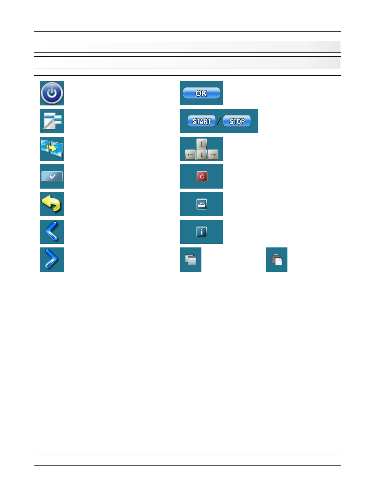
8.1.1. BUTTON S
Button ’’START’’/’’STOP’’
Button ’’ON / OFF’’
options: on / off boiler operation’’
Button ’’DISPLAY SELECTION’’
options: main menu / work
Button ’’BOILER OPERATION DISPLAY’’
options: graphic / numeric
Button ’’ENTER’’
Button ’’BACK’’
Button’’PREVIOUS SCREEN’’
Button ’’NEXT SCREEN’’
Button ’’OK’’
Navigation buttons:
’’LEFT’’, ’’RIGHT’’, ’’UP’’, ’’DOWN’’
Button ’’DELETE’’
Button ’’FACTORY SETTINGS’’
Button ’’INFORMATION’’
Button ’’COPY’’ Button ’’PASTE’’
8.1. BOILER CONTROL UNIT USE
15
49
Technical instructions BioTec Plus
Page 50
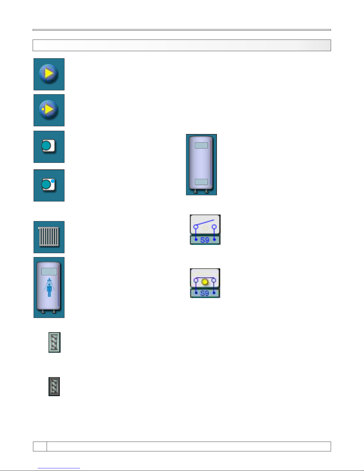
The pump has a request for work (next to the pump symbol bright yellow square when
the consumer given the demand for work the pump, the pump does not work if you have
not met all the conditions for work, for example. low temp. in the boiler, otherwise the
pump normally works)
Pump (when pump is working symbol is rotating, otherwise idle)
70°C
50°C
Accumulation tank with current
temperature at top of the tank and
at the bottom of the tank.
55°C
Domestic hot water tank
with current temperature
Heating circuit
Room thermostat
Next to the room thermostat
symbol bright blue circle (the
room thermostat has requested
for operating the pump, the pump
does not work if you have not met
all the conditions for its operation,
for example. low temp. in the
boiler, otherwise normally works)
8.1.2. SYMBOLS
Cleaning of flue pass.
(this symbol is located in
left side-wood)
Pellets reffil
(this symbol is located in
left side-wood)
External control require burner
operation (this symbol
is visible only if external control
is installed and configured)
Burner operation is not required
by external control (this symbol
is visible only if external control
is installed and configured)
Technical instructions BioTec Plus
50
Page 51
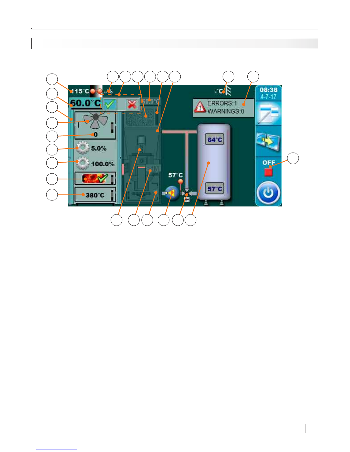
8.1.3. MAIN SCREEN
1a
1b
2
4
3
6
7
8
9
10
11
19 2018
17
16
15
5
12
13 14
2221
23
1a - Boiler (Wood firing side)
1b - Boiler (Pellet firing side)
2 - Buffer tank
3 - Boiler pump P1
4 - 3 - way protection valve
(thermic or with actuator)
5 - Boiler temperature (Wood firing
side)
6 - Symbol of fan operation
(simbol is rotate when fan working)
7 - Fan speed (rpm)
8 - Simbol and opening percentage of
primary air actuator
9 - Simbol and opening percentage of
secondary air actuator
10 - Glow option (if is enabled)
11 - Combustion chamber temperature
12 - Flue gas temperature
13 - The percentage of oxygen in the flue gases
(lambda probe)
14 - Boiler side activity indicator
15 - Wood pellet tank
16 - Boiler temperature (Wood pellet firing side)
17 - Fuel level sensor (Wood pellets)
18 - Feeder screw
19 - Photocell
20 - Electric heater
21 - Outer temperature
22 - Errors and warnings
23 - Boiler working phase
15
51
Technical instructions BioTec Plus
Page 52
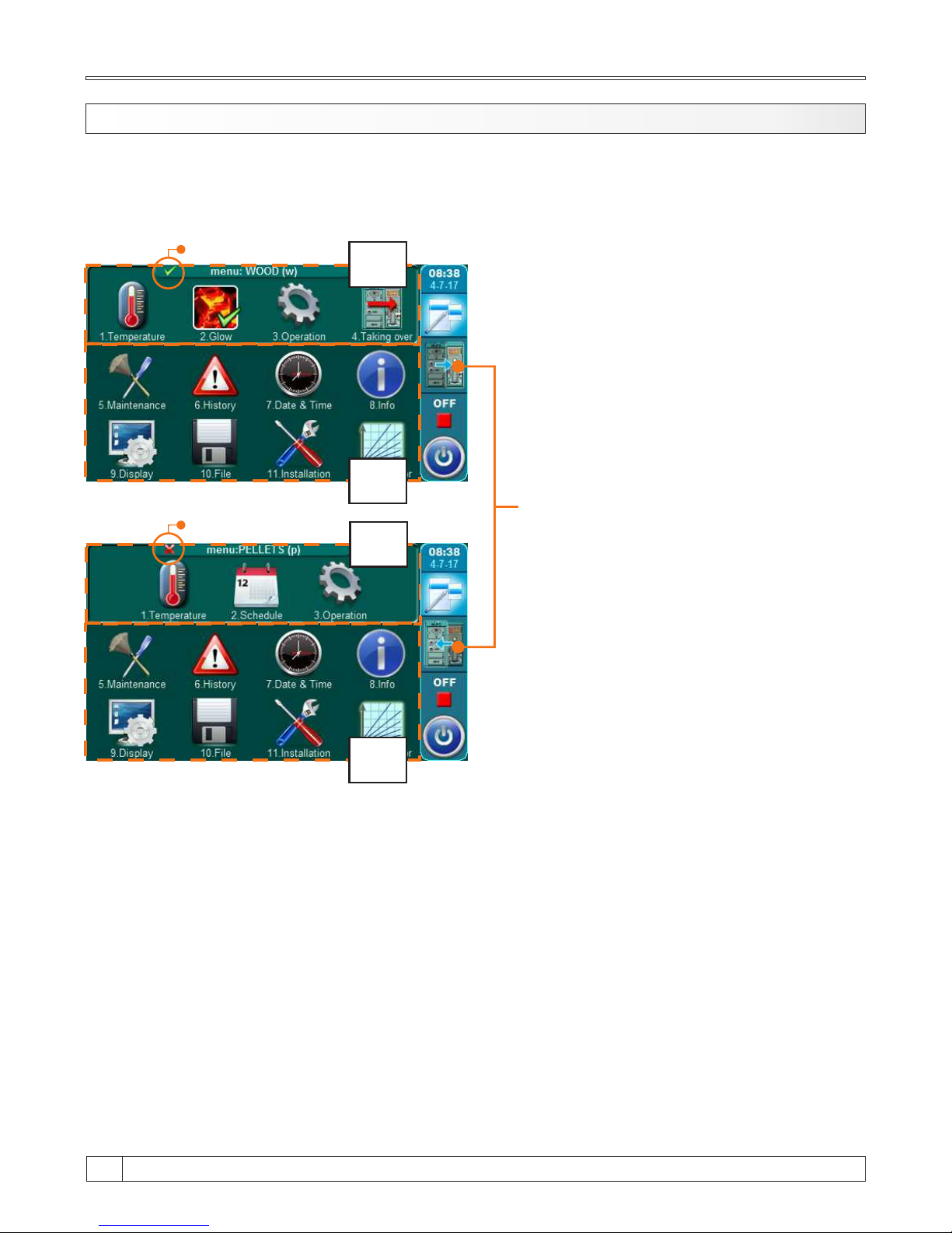
8.1.4. MAIN MENU
A
1a
1b
A
2
Button for change fuel
(WOOD(w) / PELLETS(p))
2
Main menu on BioTec Plus boiler control unit is composed of two parts - changeable part (1a and
1b) and static part (2). By pressing button for change fuel (see image below) displayed parameter
will be changed. Displaying parameters can be changed regardless of boiler working phase and
which fuel are choosen as active for work.
1a - WOOD(w) menu (changeable menu) - menu for using parameters at wood firing (left side of
the boiler)
1b - PELLETS(p) menu (changeable menu) - menu for using parameters at wood pellet firing
(right side of the boiler)
2 - static part of main menu - this part of main menu is always same
Technical instructions BioTec Plus
52
Page 53
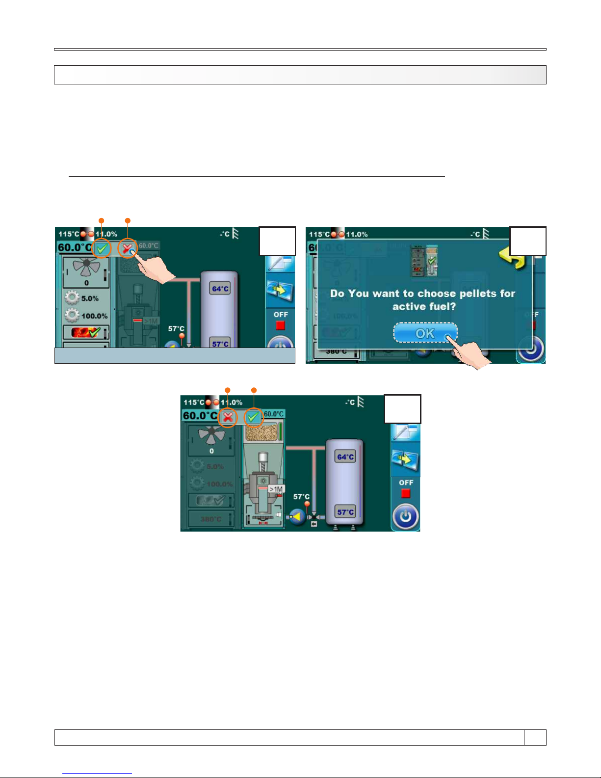
Using of BioTec Plus boiler are consist of using of left part of the boiler (fuel: wood) and using of
right part of the boiler (fuel: wood pellets). On boiler control unit is necessary to choose which side
of the boiler will be used (which fuel will be used). Below is shown procedure for choosing boiler
side for work when is boiler turned off (working phase „OFF”).
PROCEDURE FOR CHOOSING BOILER SIDE FOR WORK (USED FUEL):
Example: Selecting wood pellets for active fuel (right side of the boiler).
Left and right side of the boiler have indicators (A and B) which shows which of these two side are
active (which fuel are choosen). Active side have green indicator, inactive side have red indicator
(red „x”). On figure above is example for switching from left side of the boiler to the right side of the
boiler (from wood to wood pellets). It’s necessary to press and hold for 3 seconds indicator on
inactive boiler side (figure 1, indicator B). On display will be displayed message „Do you want
choose wood pellets for active fuel?” (figure 2). Press „OK” button (figure 2). Now left side of the
boiler have red inactive indicator, right side of the boiler have green indicator of activity (figure 3.).
2
8.1.5. CHOOSING BOILER SIDE (choosing fuel)
15
53
Technical instructions BioTec Plus
1
Maintenez ce bouton pour 3s!
A B
3
A B
Page 54
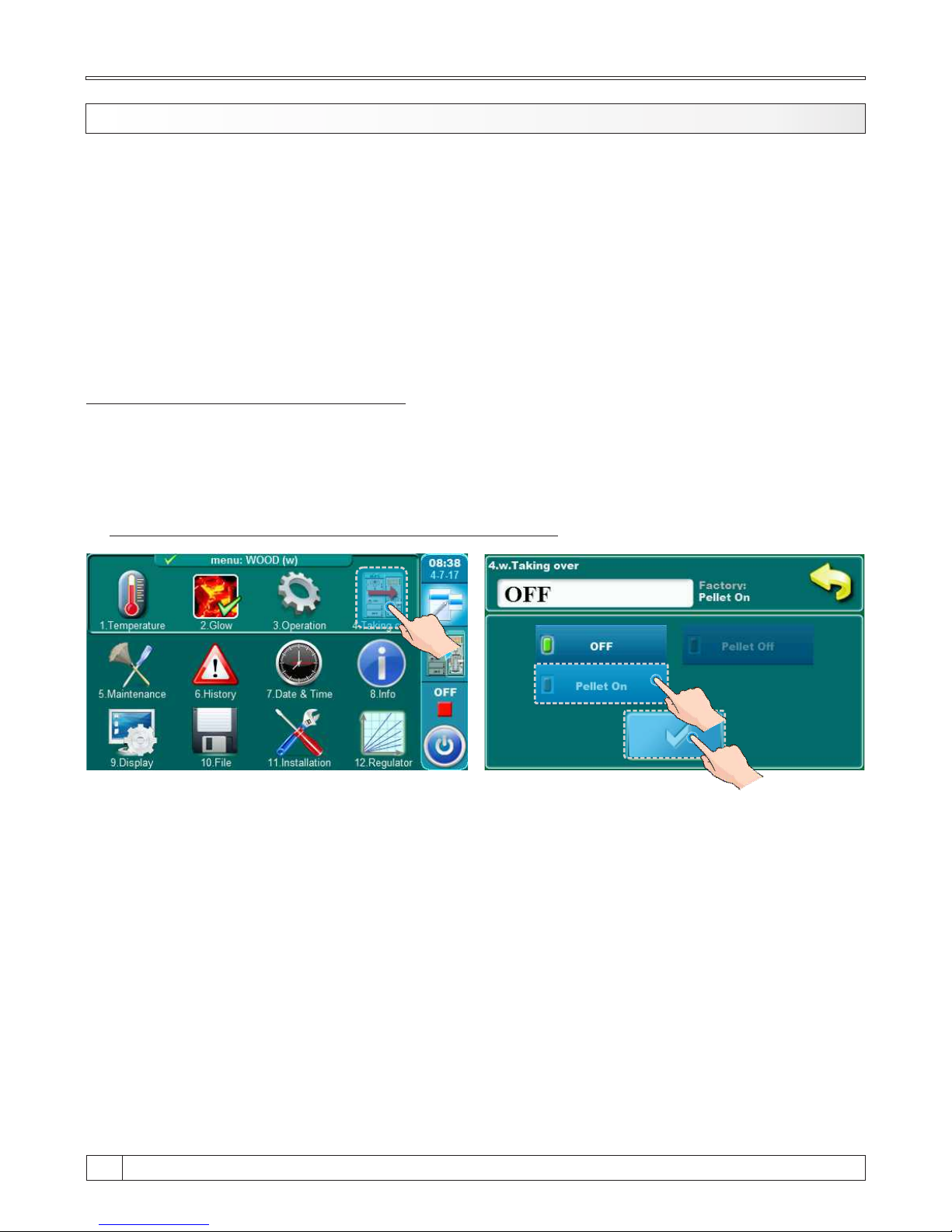
8.1.6. TAKING OVER
Note: Option „Taking over” is possible only from left side of the boiler (fuel: wood) to right
side of the boiler (fuel: wood pellets) (wood pellets taking over wood).
„Taking over” option is used for automatic switching operation from one fuel to another fuel.
Automatic switch is possible only from wood to wood pellets.
For use of „Taking over” option is neccesary to activate it (see „Activating „Taking over” option”).
„Taking over” option works on the way that when left part of the boiler (fuel: wood) runs out of the
fuel, right side of the boiler (fuel: wood pellets) automatic take over work activity and right side of
the boiler (fuel: wood pellets) continues with work.
ACTIVATING „TAKING OVER” OPTION
Activating „Taking over” option can be done on two ways:
a) through main menu (menu: WOOD(w), „Taking over” submenu)
b) through main screen by pressing boiler side status indicator
a) activating „Taking over” option through main menu
On main menu (menu: WOOD(w)) (see Point „8.1.4. Main menu”) choose submenu „4. Taking
over”, select „Pellet On” and confirm it by pressing „Confirm” button.
Technical instructions BioTec Plus
54
Page 55
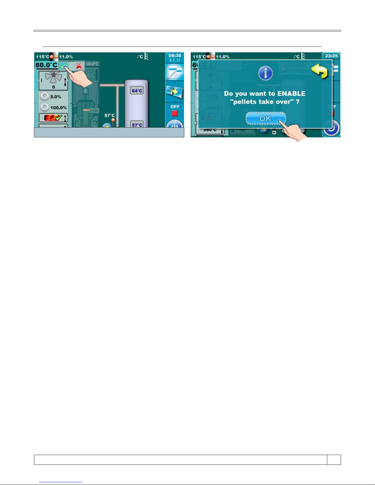
Hold this button for 3s!
a) activating „Taking over” option through main screen (boiler side activity indicator)
Press green activity indicator on right boiler side (fuel: wood) and hold it for 3 seconds. On display
will be desplayed „Do you want to ENABLE „pellets take over?”. Confirm it by pressing „Confirm”
button.
Hold this button for 3s!
15
55
Technical instructions BioTec Plus
Page 56
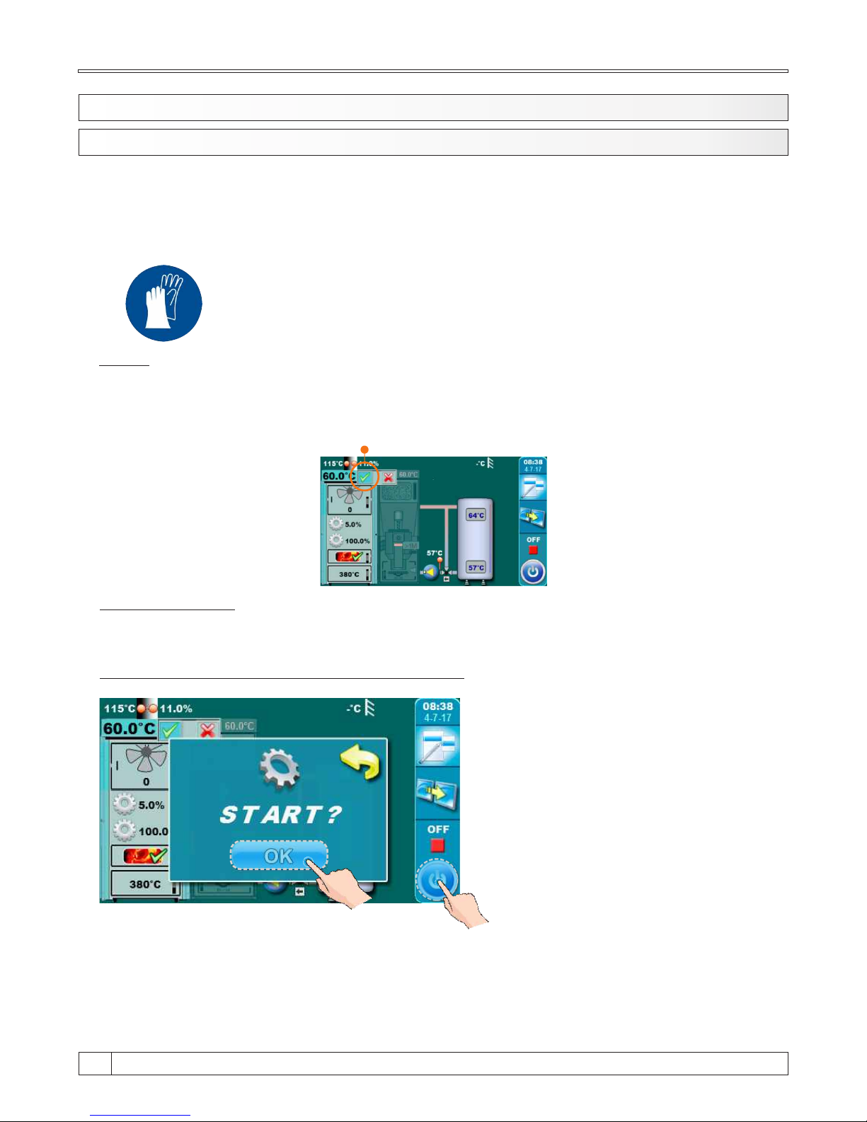
8.2. USE THE LEFT SIDE OF THE BOILER - FUEL: WOOD
8.2.1. IGNITION
Boiler must not be used in flammable and explosive environment. It must not be used by children
or disabled persons (either physically or mentally), as well as by person without knowledge or
experience, unless they are under control or trained by s person responsible for their safety.
Children must be supervised in the vicinity of the product. Protective gloves must be used!
Protective gloves must be used!
NOTE:
Before ignition make sure that is left side of the boiler selected like active (see indicator „A” on
figure below) (for procedure for choosing boiler side for work (used fuel) view point 8.0. „Boiler
use” in this technical instructions).
IGNITION PHASE:
- Open upper and middle boiler doors (see pages 4 i 5 in this technical instructions”)
Follow these steps for succesfull igniton phase:
- press button for boiler start
- on display will be displayed window for
boiler start
- press ”OK” button
Technical instructions BioTec Plus
56
A
Page 57
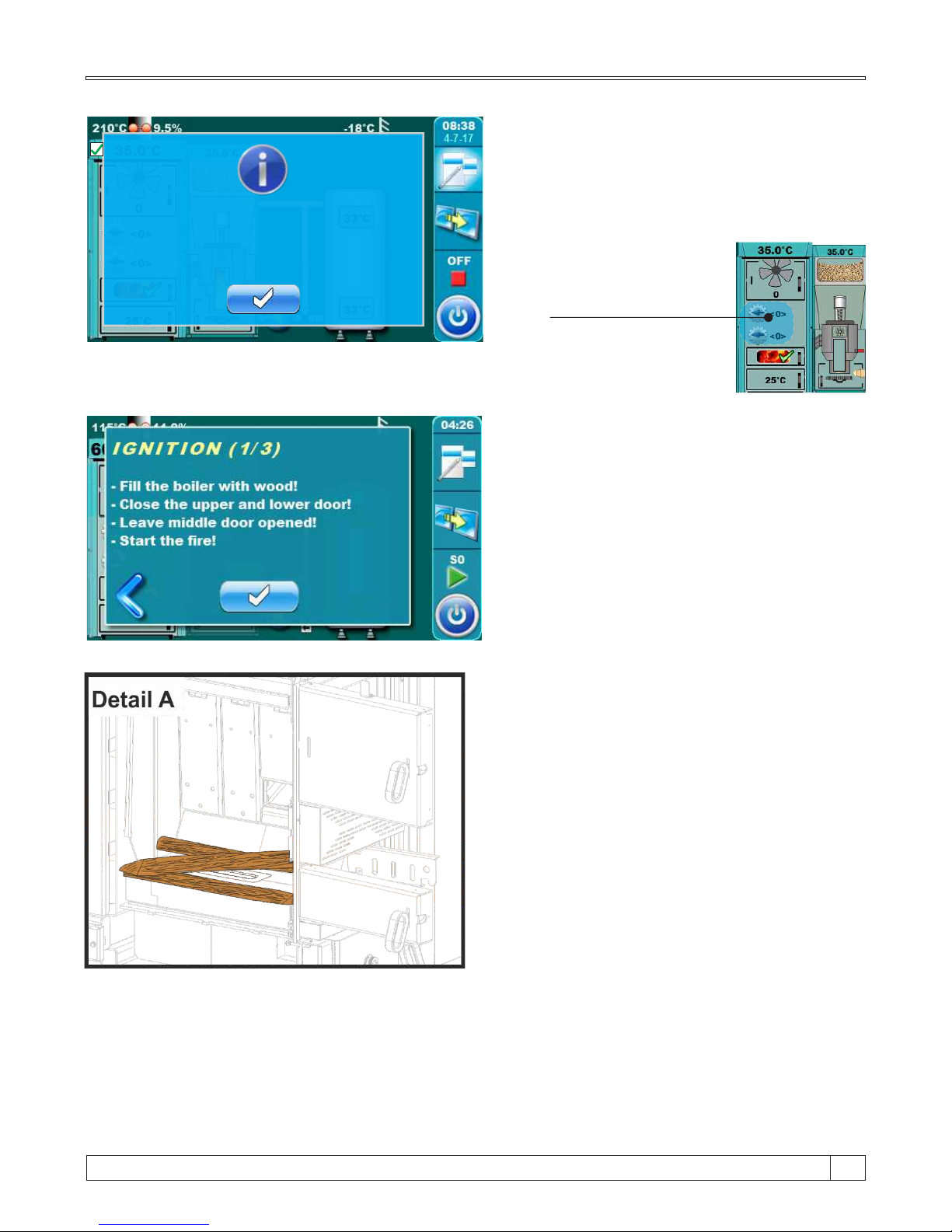
Primary and secondary wings
seeking initial position. Please
wait and try again.
- if this message is shown on display than
wait for primary and secondary air
actuators
- primary and secondary air is
ready for work when indicator
stop blinking
Primary and secondary
air indicators.
- on display is displayed message
"IGNITION 1/3"
- cover the refractory stone with one row
of wood logs (be careful to not plug hole
on refractory stone (detail A)
- cover the wood logs with fine chopped wood
(use enough fine chopped wood to cover
wood logs below)
- height of fine chopped wood layer must
conform a approx. height of first row of wood
logs
- cover the fine chopped wood with crumped
paper (use enough crumpled paper to cover
fine chopped wood) (detail B)
- place the wood logs on crumpled paper
- fill the fuel loading chamber with wood logs
(detail C)
- close upper and lower doors
- leave middle door opened
- ignite the fire throuh middle boiler door
(detail C)
- press enter button” “
15
57
Technical instructions BioTec Plus
Page 58
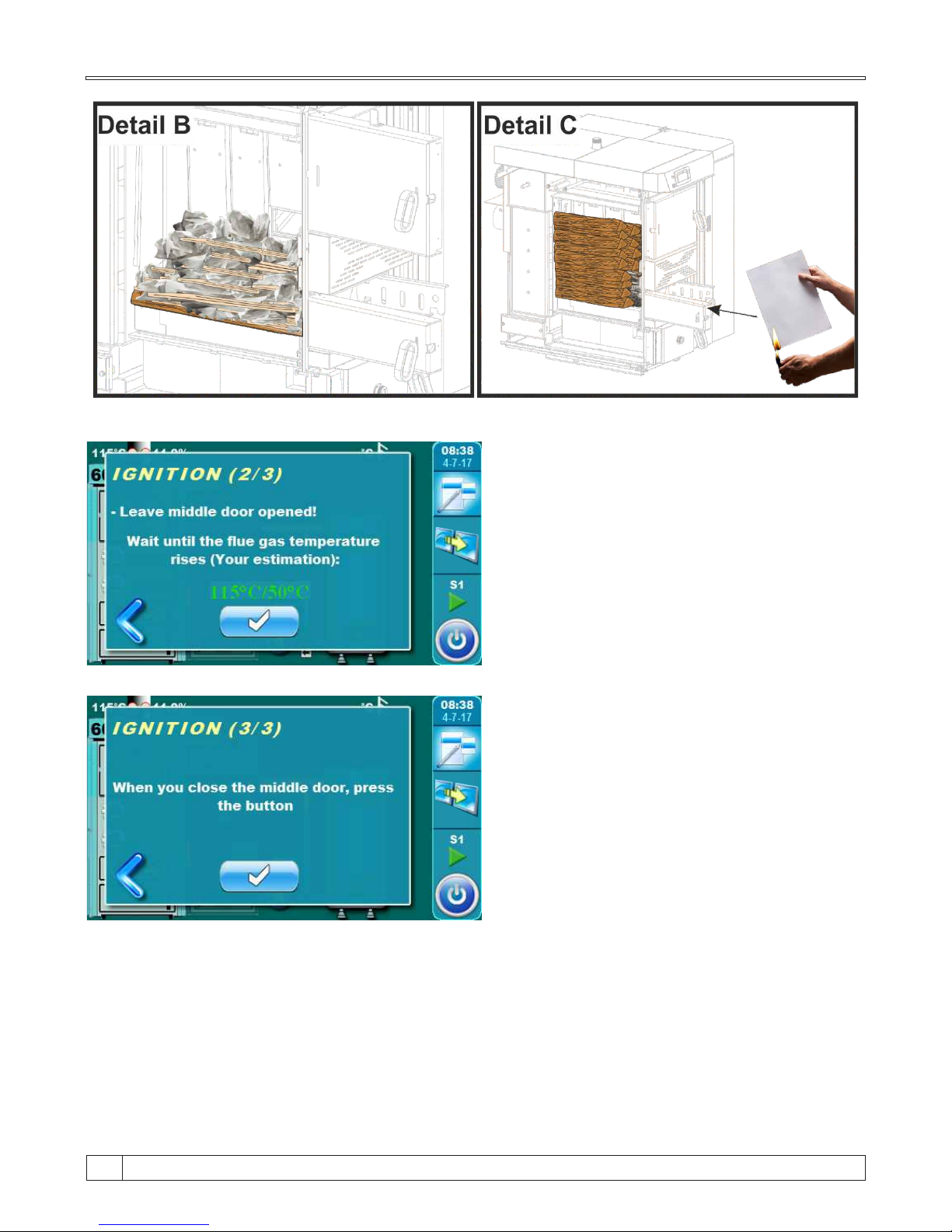
- on display is displayed message
"IGNITION 3/3"
- close middle boiler door
- press ”enter” button
- on display is displayed message
"IGNITION 2/3"
- on this step is neccessary to wait until flue
gas temperature raise 50°C
- middle boiler door must be opened all time
- when is flue gas temperature higher than
50°C press ”enter“ button
Technical instructions BioTec Plus
58
Page 59
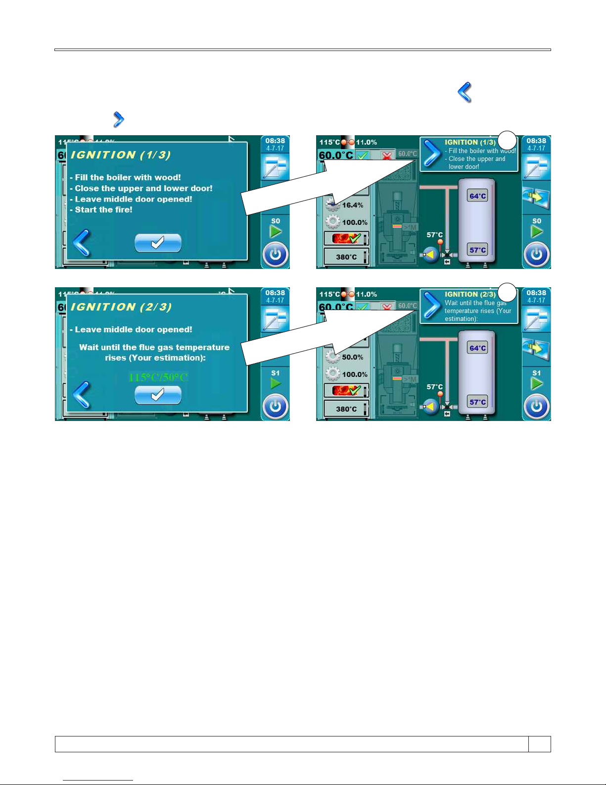
Additional:
During ignition phase is possible to see main display. It is neccessary to press button.
Because ignition phase is on proces, display will be displayed current ignition step to (1). By
pressing button we return to full preview of ignition phase.
1
1
15
59
Technical instructions BioTec Plus
Page 60
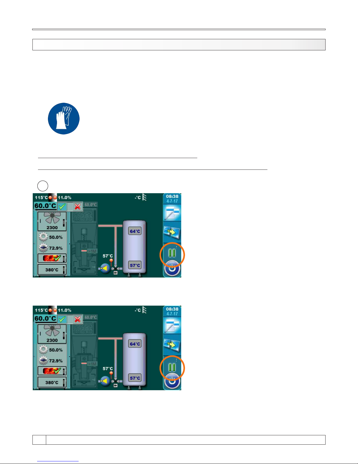
8.2.2. REFILLING
Boiler must not be used in flammable and explosive environment. It must not be used by children
or disabled persons (either physically or mentally), as well as by person without knowledge or
experience, unless they are under control or trained by s person responsible for their safety.
Children must be supervised in the vicinity of the product. Protective gloves must be used!
PHASE OF REFILLING FUEL LOADING CHAMBER:
For successful refilling of the fuel loading chamber follow the next steps:
1.
When on display is displaying boiler
operating phase „GLW2" that is mean the
boiler have spent all the fuel and it’s
remaining only glow in the fuel loading
chamber.
In this step is neccessary to open upper boiler door and check if it glow quality good enough for firing
continue and refilling wood loading chamber or it is necessary to go on ignition phase again.
When you open upper boiler door (see pages
4 i 5 in this technical instructions) than is
displayed boiler operation phase „DOP0".
If you estimate that the glow is good enough for refilling wood load chamber with fuel it’s neccessary
to folow next steps. If you estimate that the glow is not good enough for refilling wood load chamber
follow steps in point „Procedure if glow is not enough good”. After glow checking is neccessary to
close upper boiler door.
Protective gloves must be used!
Technical instructions BioTec Plus
60
GLW2
DOP0
Page 61
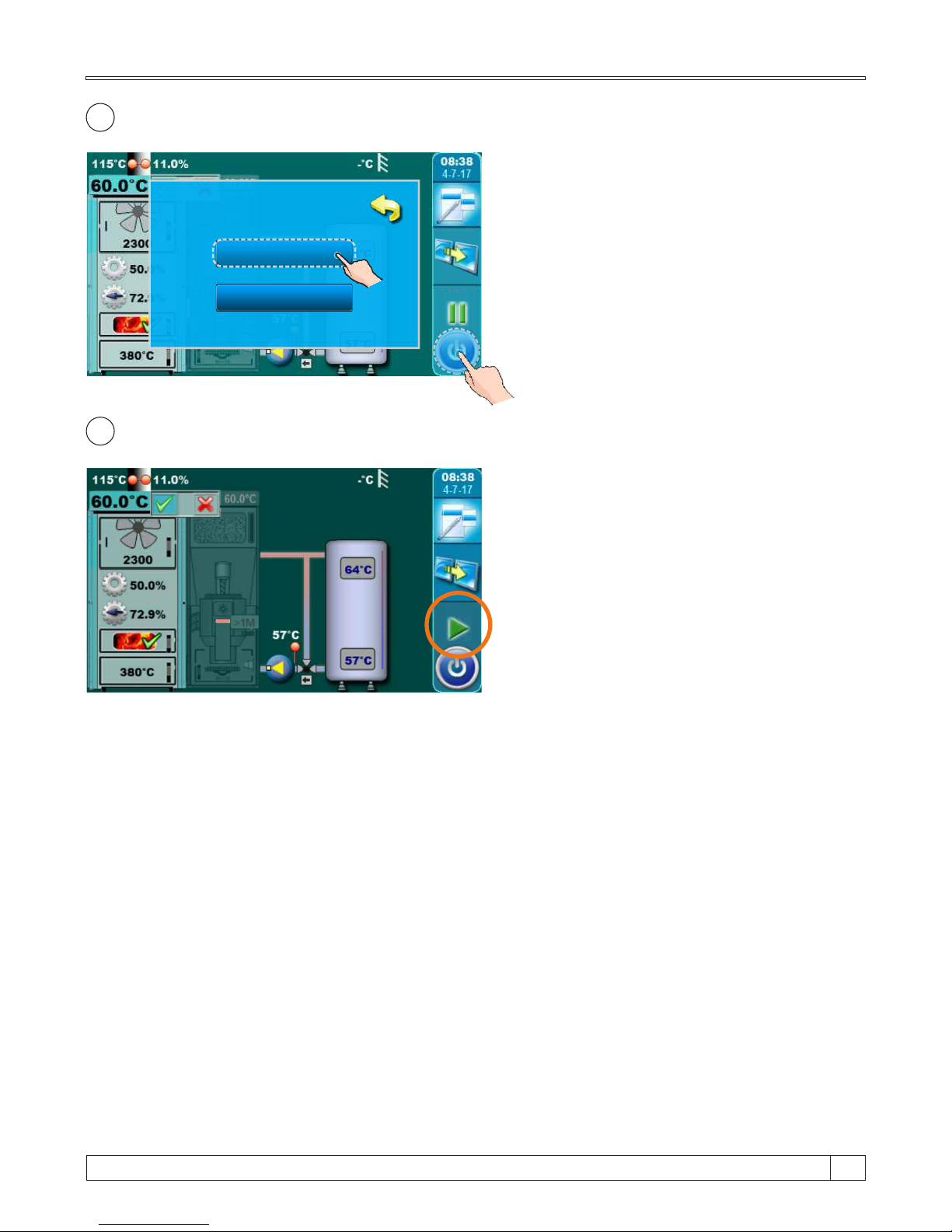
2.
Press button „START / STOP“, on display will
be displayed window with offered options
„NEW LOADING“ and „OFF“. Press button
„NEW LOADING“.
3.
On display is displaying boiler operating
phase „SP1".
Description of the refilling wood loading chamber:
- open upper boiler door (see pages 4 i 5 in this technical instructions).
- align the glow with scraper
- based on estimates of glow quality and amount of glow put more or less dry thin wood (depend
about estimate) and after that fill the wood loading chamber with wood
- close upper boiler door (see pages 4 i 5 in this technical instructions)
ACTION:
NEW LOADING
OFF
GLW2
15
61
Technical instructions BioTec Plus
SP1
Page 62
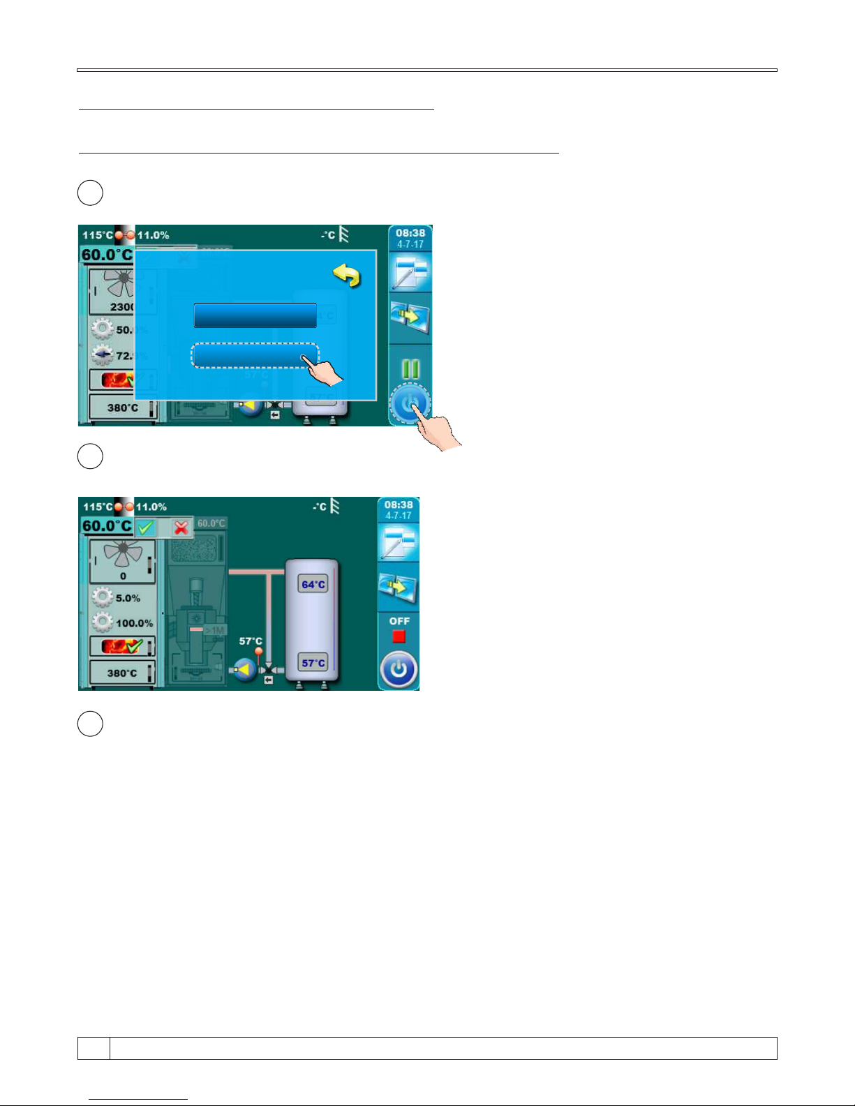
1.
Press button „START / STOP“, on display will
be displayed window with offered options
„NEW LOADING“ and „OFF“. Press button
„OFF.
2.
Wait until on display is displayed boiler
operating phase „OFF”.
3.
Go to the ignition phase like is described in point „IGNITION” in this technical instructions.
PROCEDURE IF GLOW IS NOT ENOUGH GOOD
If glow is not enough good for fuel refilling folow the next steps:
ACTION:
NEW LOADING
OFF
GLW2
Technical instructions BioTec Plus
62
Page 63
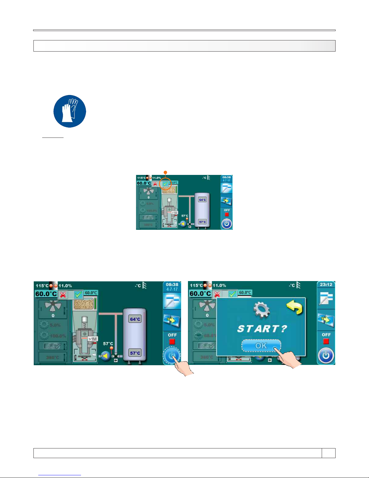
8.3. USE THE RIGHT SIDE OF THE BOILER - FUEL: WOOD PELLETS
Boiler must not be used in flammable and explosive environment. It must not be used by children
or disabled persons (either physically or mentally), as well as by person without knowledge or
experience, unless they are under control or trained by s person responsible for their safety.
Children must be supervised in the vicinity of the product. Protective gloves must be used!
Protective gloves must be used!
NOTE:
Before ignition make sure that is right side of the boiler selected like active (see indicator „A” on
figure below) (for procedure for choosing boiler side for work (used fuel) view point 8.0. „Boiler
use” in this technical instructions).
BOILER START:
For boiler start is neccesary to press ON / OFF button. After pressing ON / OFF button on display
will be displayed window for boiler start confirmation. Press „OK” to confirm boiler start.
15
63
Technical instructions BioTec Plus
A
Page 64
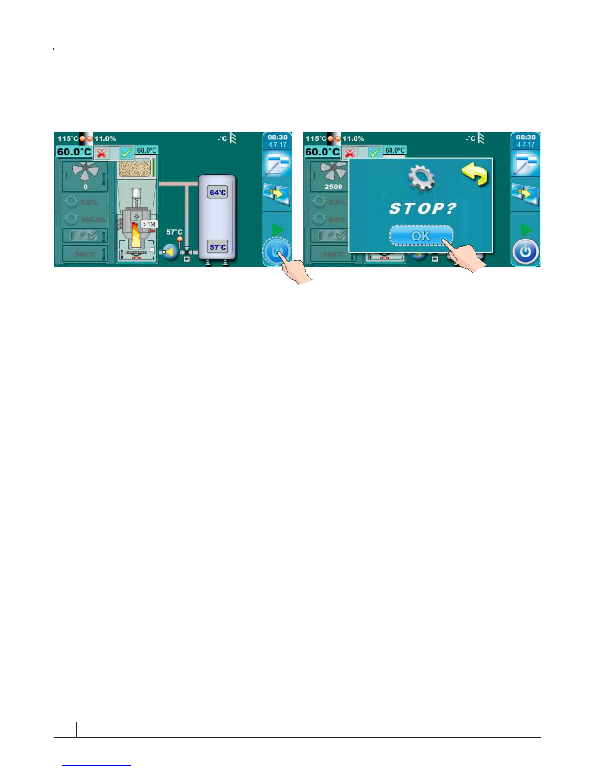
BOILER STOP:
For boiler stop is neccesary to press ON / OFF button. After pressing ON / OFF button on display
will be displayed window for boiler stop confirmation. Press „OK” to confirm boiler stop.
D5
D5
D5
D5
Technical instructions BioTec Plus
64
Page 65
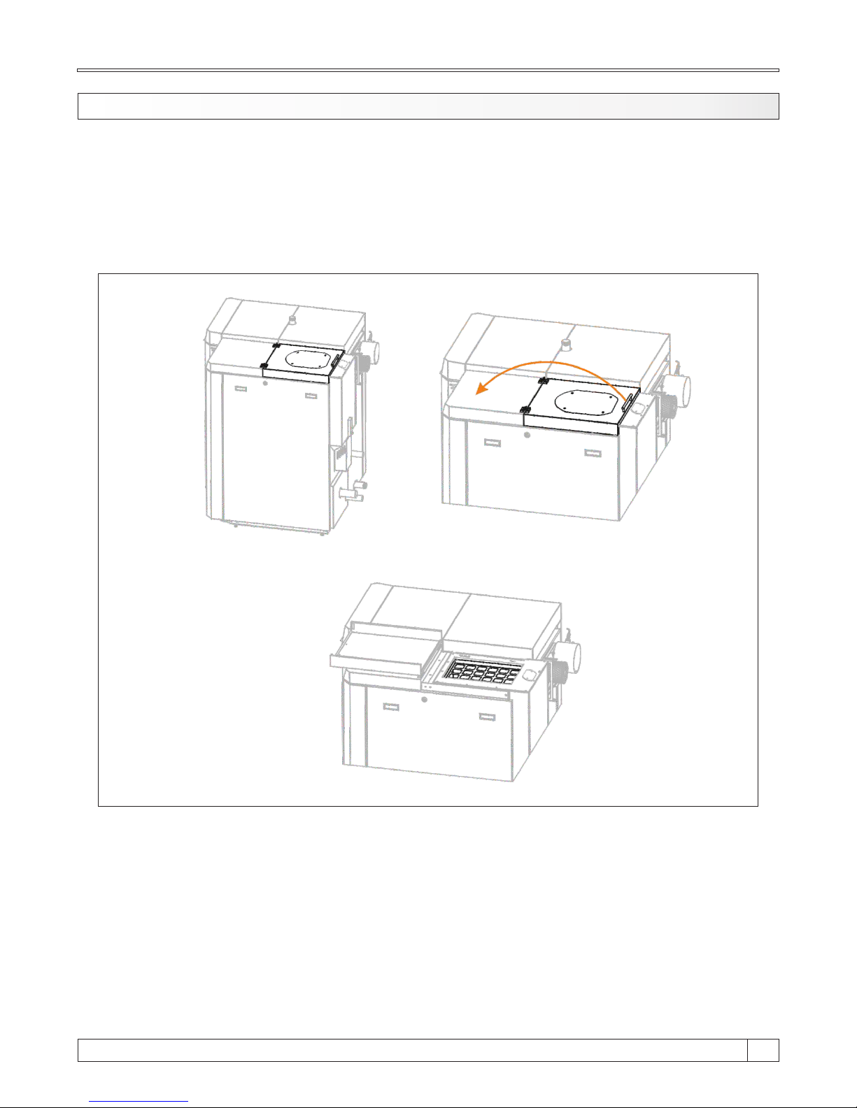
8.3.1. REFFILING OF WOOD PELLETS
Wood pellet is manual filling on right upper side of the boiler (pellet part) (see figure below). It’s
necessary to open casing cover using the handle.
IMPORTANT:
At filling wood pellet tank it must be filled at least 2/3 of capacity for correct work of wood
pellet level sensor!
15
65
Technical instructions BioTec Plus
Page 66
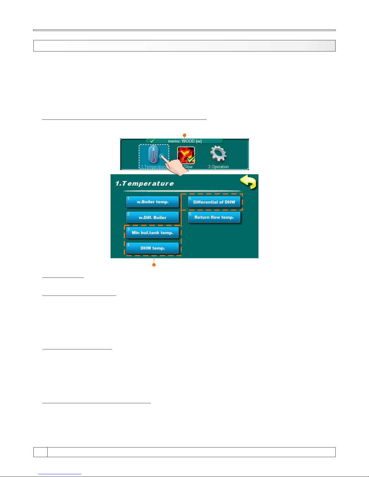
x.x.x. TEMPERATURE ADJUSTMENT 8.4. TEMPERATURE ADJUSTMENT
Temperature adjustment are performed seperately for left (fuel: wood) and right (fuel: wood
pellets) side of the boiler. For adjustment left side of the boiler (fuel: wood) temperature it’s
necessary to choose menu for wood firing (WOOD(w)). For adjustment right side of the boiler
(fuel: wood pellets) temperature it’s necessary to choose menu for wood pellet firing
(PELLETS(p)).
Fuel: Wood
SUBMENUS:
1. w.Boiler temperature
In this submenu is possible to adjust boiler working temperature.
- Factory adjusted: 85°C
- Adjustment range: 75°C - 90°C
2. w.Differential Boiler
In this submenu is possible to adjust differential for boiler working temperature.
- Factory adjusted: 5°C
- Adjustment range: 5°C - 7°C
3. Minimal buffer tank temperature
In this submenu is possible to adjust minimal buffer tank temperature.
- Factory adjusted: 20°C
- Adjustment range: 5°C - 85°C
This submenus depend about DHW configuration
TEMPERATURE ADJUSTMENT FOR WOOD FIRING
Technical instructions BioTec Plus
66
Page 67

4. DHW temperature (depend about DHW configuration)
In this submenu is possible to adjust domestic hot water temperature.
- Factory adjusted: 50°C
- Adjustment range: 40°C - 80°C
5. Differential of DHW (depend about DHW configuration)
In this submenu is possible to adjust differential of domestic hot water temperature.
- Factory adjusted: 5°C
- Adjustment range: 4°C - 40°C
6. Return flow temperature
In this submenu is possible to adjust return flow temperature.
- Factory adjusted: 60°C
- Adjustment range: 60°C - 70°C
15
67
Technical instructions BioTec Plus
Page 68
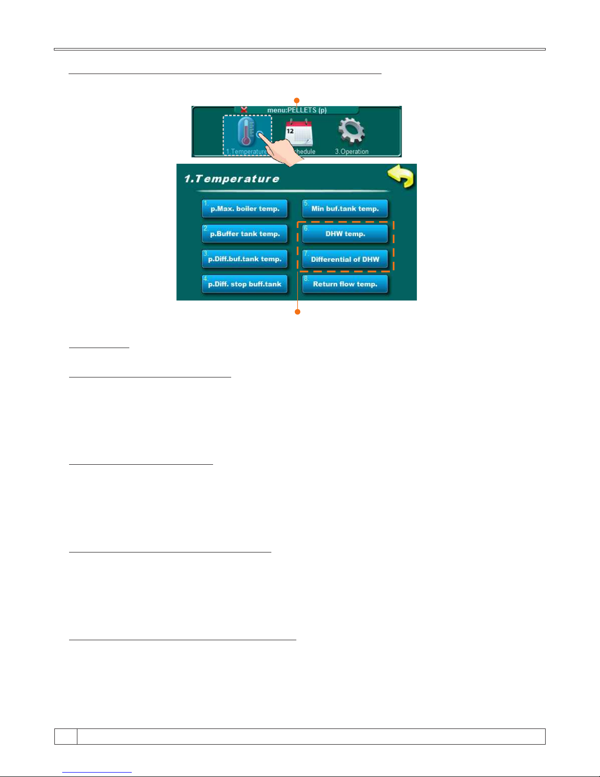
Fuel: Wood pellets
This submenus depend about DHW configuration
Submenus:
1. p.Maximal boiler temperature
In this submenu is possible to adjust maximal boiler working temperature.
- Factory adjusted: 80°C
- Adjustment range: 70°C - 90°C
2. p.Buffer tank temperature
In this submenu is possible to adjust buffer tank temperature.
- Factory adjusted: 80°C
- Adjustment range: 40°C - 85°C
3. p.Differential buffer tank temperature
In this submenu is possible to adjust differential for buffer tank temperature.
- Factory adjusted: 10°C
- Adjustment range: 5°C - 30°C
4. p.Differential stop buffer tank temperature
In this submenu is possible to adjust differential stop for buffer tank temperature.
- Factory adjusted: 5°C
- Adjustment range: 3°C - 30°C
TEMPERATURE ADJUSTMENT FOR WOOD PELLET FIRING
Technical instructions BioTec Plus
68
Page 69

5. Minimal buffer tank temperature
In this submenu is possible to adjust buffer tank temperature.
- Factory adjusted: 20°C
- Adjustment range: 5°C - 85°C
6. DHW temperature (depend about DHW configuration)
In this submenu is possible to adjust domestic hot water temperature.
- Factory adjusted: 50°C
- Adjustment range: 40°C - 80°C
7. Differential of DHW (depend about DHW configuration)
In this submenu is possible to adjust differential for domestic hot water temperature.
- Factory adjusted: 5°C
- Adjustment range: 4°C - 40°C
8. Return flow temperature
In this submenu is possible to adjust return flow temperature.
- Factory adjusted: 60°C
- Adjustment range: 60°C - 70°C
15
69
Technical instructions BioTec Plus
Page 70
9.0. CLEANING AND MAINTENANCE OF THE BOILER
Every millimeter of soot and dirt on the surfaces of the boiler surface means approx. 5% higher
fuel consumption. Save fuel – clean the boiler on time!
PROTECTIVE GLOVES ARE OBLIGATORY!!!
DESCRIPTION OF MAINTENANCE
INTERVAL
Cleaning ash in firebox and under firebox (through
middle and lower door - left part of the boiler) and ash tray
emptying from right part of the boiler.
Before each ignition.
Flue gas tube cleaning. Before refilling of fuel / before ignition.
Checking correctness of security valve. Every 6 months.
Cleaning of flue gas chamber. At least once per year.
Cleaning and checking the flue installation sealing. At least once per year.
At least once per year.
Cleaning of area over heat exchanger pipes with
turbulators.
Cleaning the blades and box of the fan. At least once per year.
Photocell cleaning. At least once per year.
Technical instructions BioTec Plus
70
Page 71
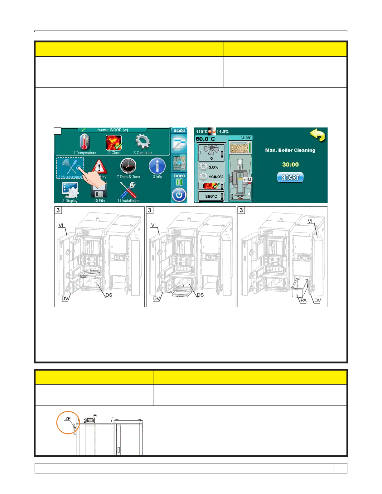
Cleaning / maintenance interval
Boiler type Description
Before each ignition
25, 35 and 45 kW
Cleaning ash in firebox and under firebox
(through middle and lower door - left part
of the boiler) and ash tray emptying from
right part of the boiler.
Before every ignition is necessary to clean area below firebox and lower refractory stone (DS)
(through middle and lower boiler door (DV)) and empty ashtray (PA) from the side of the right
boier. Before cleaning is necessary to turn on option "cleaning". Fan will work at maximun speed
to reduce the spread of dust to the room. When you finish cleaning, press the "STOP" button. If
time of 30:00 minutes has expired cleaning option (fan) will automatically turn off.
1. Press button ”Cleaning“ on main screen
2. Press button ”OK“
3. Open front boiler door (VI).
4. Open middle boiler door
5. Open lower boiler door (DV).
6. Insert the ashtray to the middle gate (1) and
clean up firebox with scraper and push the ash
on the ashtray.
7. Insert the ashtray under lower door and
use scraper to clean refractory stone(DS) and
push ash on the astray.
8. Empty ashtray
9. Take out ash tray (PA) from right side of the boiler.
10. Empty ashtray (PA) and place it back.
11. After cleaning, the boiler is ready for ignition.
Cleaning / maintenance interval
Boiler power Description
Before refilling of fuel / before
ignition
25, 35 and 45 kW
Flue gas tubes cleaning
For flue gas tubes cleaning in necessary to pull lever (ZP) few
times.
1 2
15
71
Technical instructions BioTec Plus
Page 72
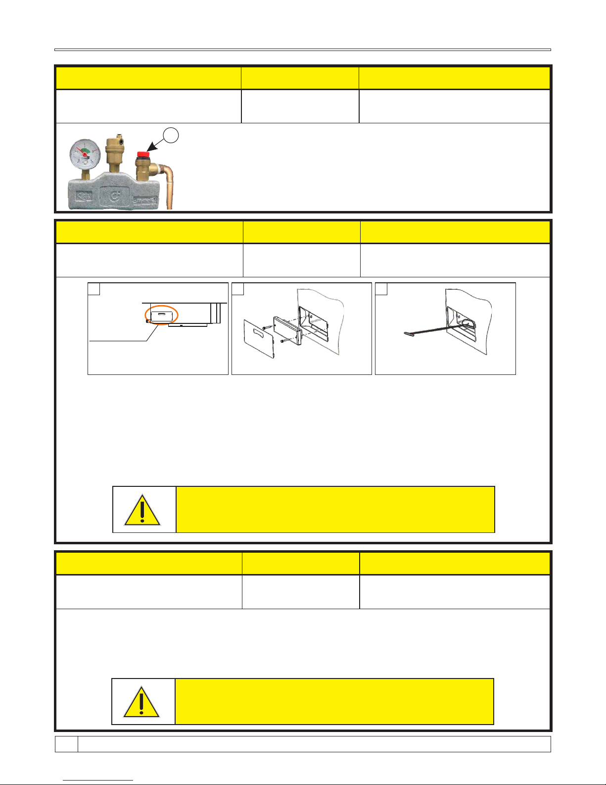
Lateral opening
for cleanign the
flue gas chamber
(on left side of the
boiler)
BioTec Plus
1 2 3
Checking the correctness of security valve
By briefly turning the cap of safety valve (C) check whether water coming
out from the safety valve. If no water comes out after several repeated
checks, then is necessary to replace the safety valve.
Cleaning / maintenance interval
Boiler power Description
Every 6 months
25, 35 and 45 kW
Check the correctness of security
valve
C
Cleaning / maintenance interval
Boiler power Description
At least once per year.
25, 35 and 45 kW
Cleaning of flue gas chamber.
1 - Switch off the boiler and disconnect from electric. power.
2 - Before cleaning flue gas chamber, pull lever (ZP) few times (see ”flue gas tubes cleaning“)
3 - Take out insulation cover, unscrew two screws which hold door of flue gas chamber.
4 - Insert ashtray and clean the flue gas chamber with scraper.
5 - Put the doors and insulation cover to original position.
Note: For the proper operation of the boiler it is IMPORTANT to hard tight the doors how
it to seal perfectly!
Before this procedure be sure to disconnect boiler from
electric. power!!!
Cleaning / maintenance interval
Boiler power
Description
At least once per year
25, 35 and 45 kW
Cleaning and checking the
flue installation sealing
Clean flue installation between the boiler and the chimney through the revision openings for
cleaning or if not incorporated revision opened by removing the flue installation. After cleaning,
inspect flue installation good sealing and seal it if the seal is not satisfactory.
Cleaning and checking the flue installation sealing
Before this procedure be sure to disconnect boiler from
electric. power!!!
Technical instructions BioTec Plus
72
Page 73
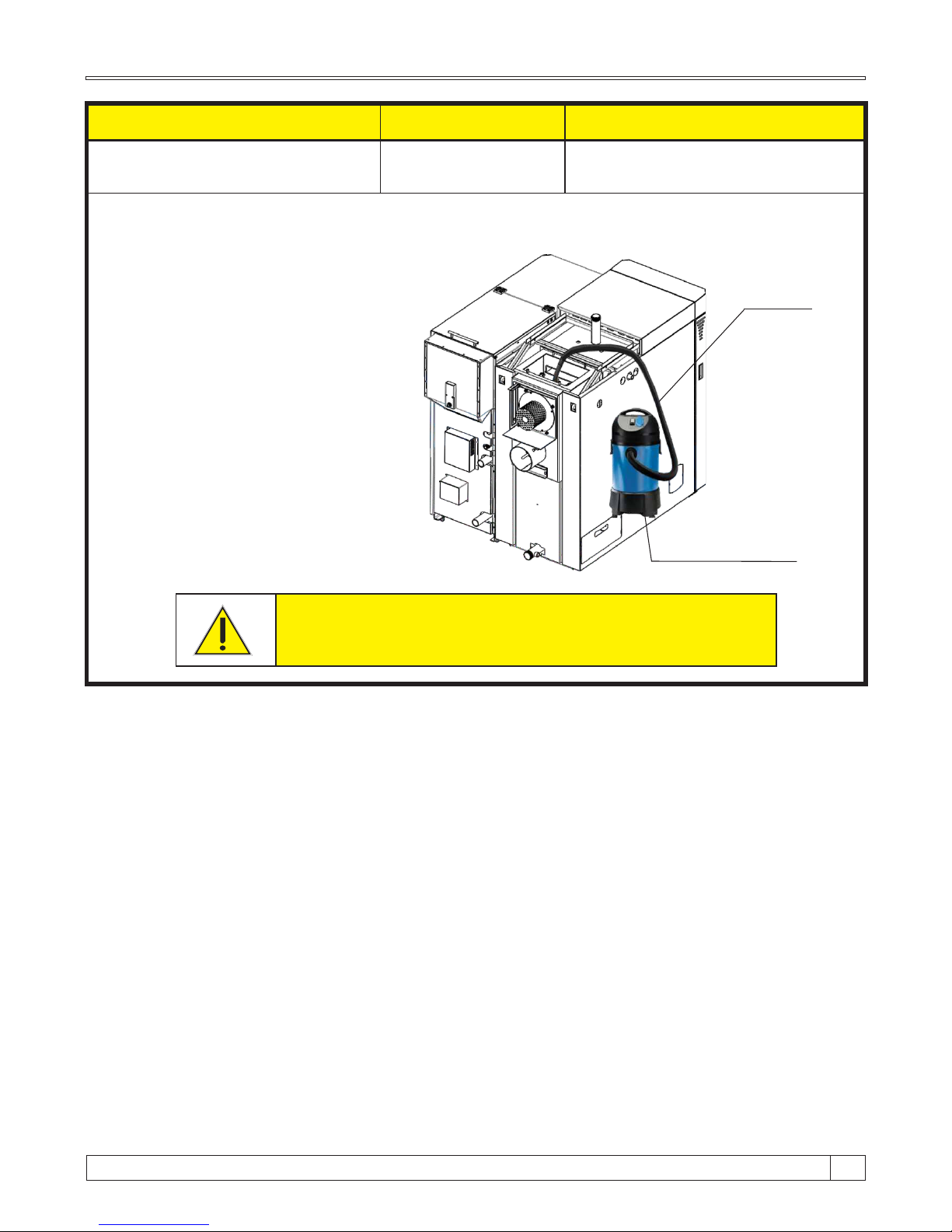
Cleaning / maintenance interval
Boiler power Description
At least once per year
25, 35 and 45 kW
Cleaning of area over heat
exchanger pipes with turbulators
Metal vacuum cleaner
1 - Switch off the boiler and disconnect from electric. power.
2 - Take out last upper cover side.
3 - Open the flue gas chamber.
4 - Use the metal vacuum cleaner to clean
dust and ash in flue gas chamber.
Before this procedure be sure to disconnect boiler from
electric. power!!!
Metal tube
15
73
Technical instructions BioTec Plus
Page 74
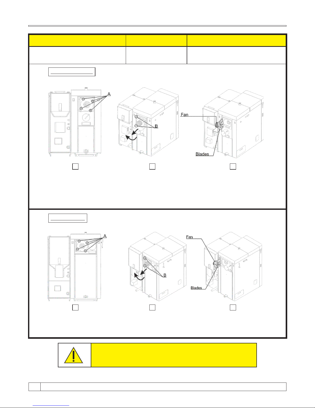
Cleaning / maintenance interval
Boiler power Description
At least once per year
25, 35 and 45 kW
Cleaning the blades and box of
the fan
1. Switch off the boiler and disconnect from electric. power.
2. Unscrew nuts (A) shown in Image 1.
3. Relase screws (B) shown in Image 2.
4. Pull out fan with flange to the end od rail, then open it to left side (see Image 2. and Image 3.).
BioTec Plus 25, 35
BioTec Plus 45
1. Switch off the boiler and disconnect from electric. power.
2. Unscrew nuts (A) shown in Image 1.
3. Relase screws (B) shown in Image 2.
4. Pull out fan with flange to the end od rail, then open it to left side (see Image 2. and Image 3.).
Before this procedure be sure to disconnect boiler from electric. power!!!
1. 2.
3.
1. 2.
3.
Technical instructions BioTec Plus
74
Page 75
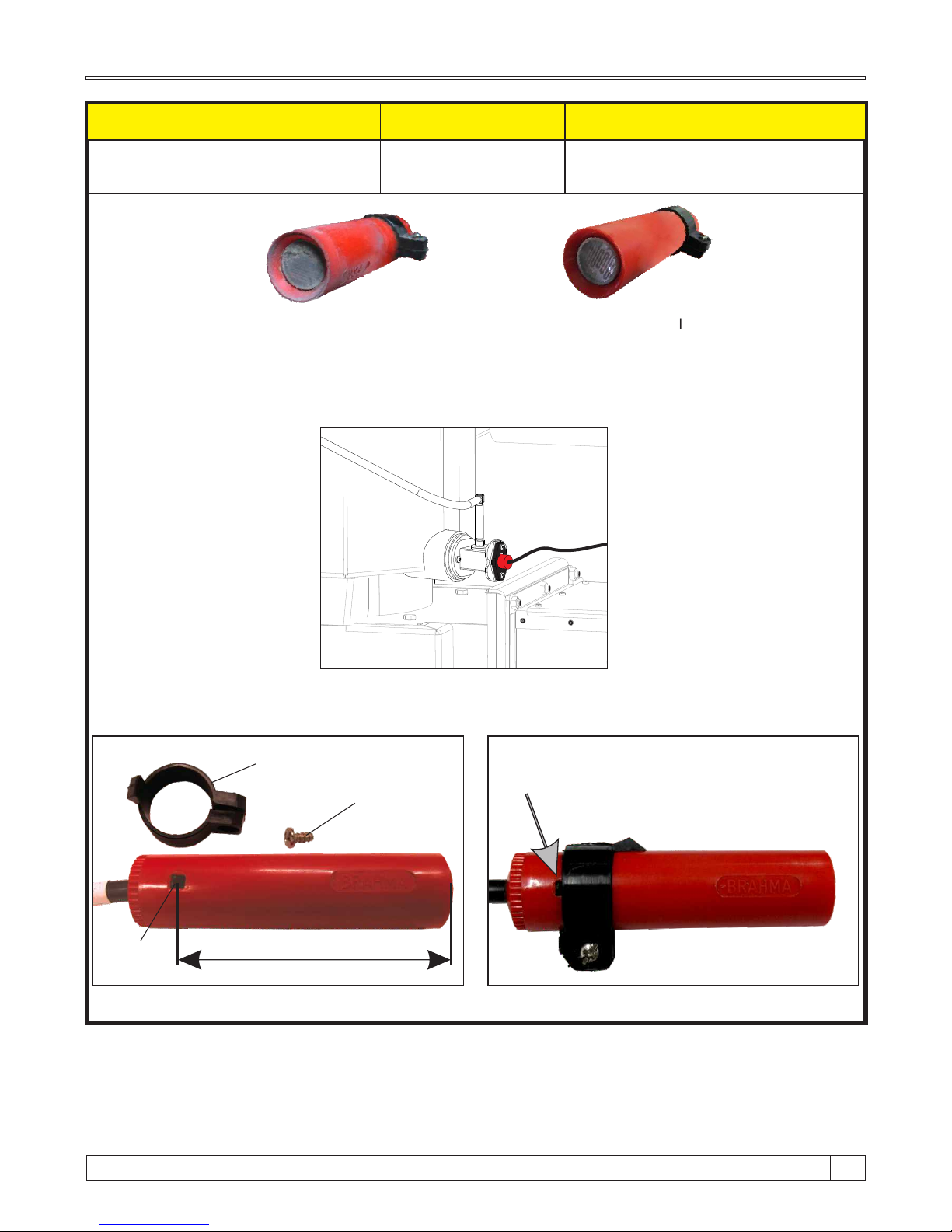
Cleaning / maintenance interval
Boiler type
Description
At least once a year
(or if you have problems
with the ignition)
25, 35 and 45 kW
Photocell cleaning
Dirty photocell which can result
error in ignition or flame dissapear
error
Valid photocell
Carefully remove the photocell from the box and then gently with a cotton swab clean the
body and lens of photocell. After cleaning, carefully return photocell to work position.
57mm
The photocell should not be set too deep or too shallow in the box. So, limiter determines the proper depth of photocell
position. Make sure the limiter is set to black mark. Black mark should be barely visible (see image below).
Limiter
Screw
Mark
The limiter must be set so that the black mark is barely
visible like is shown below (partially covered by hose
clamps)
15
75
Technical instructions BioTec Plus
Page 76
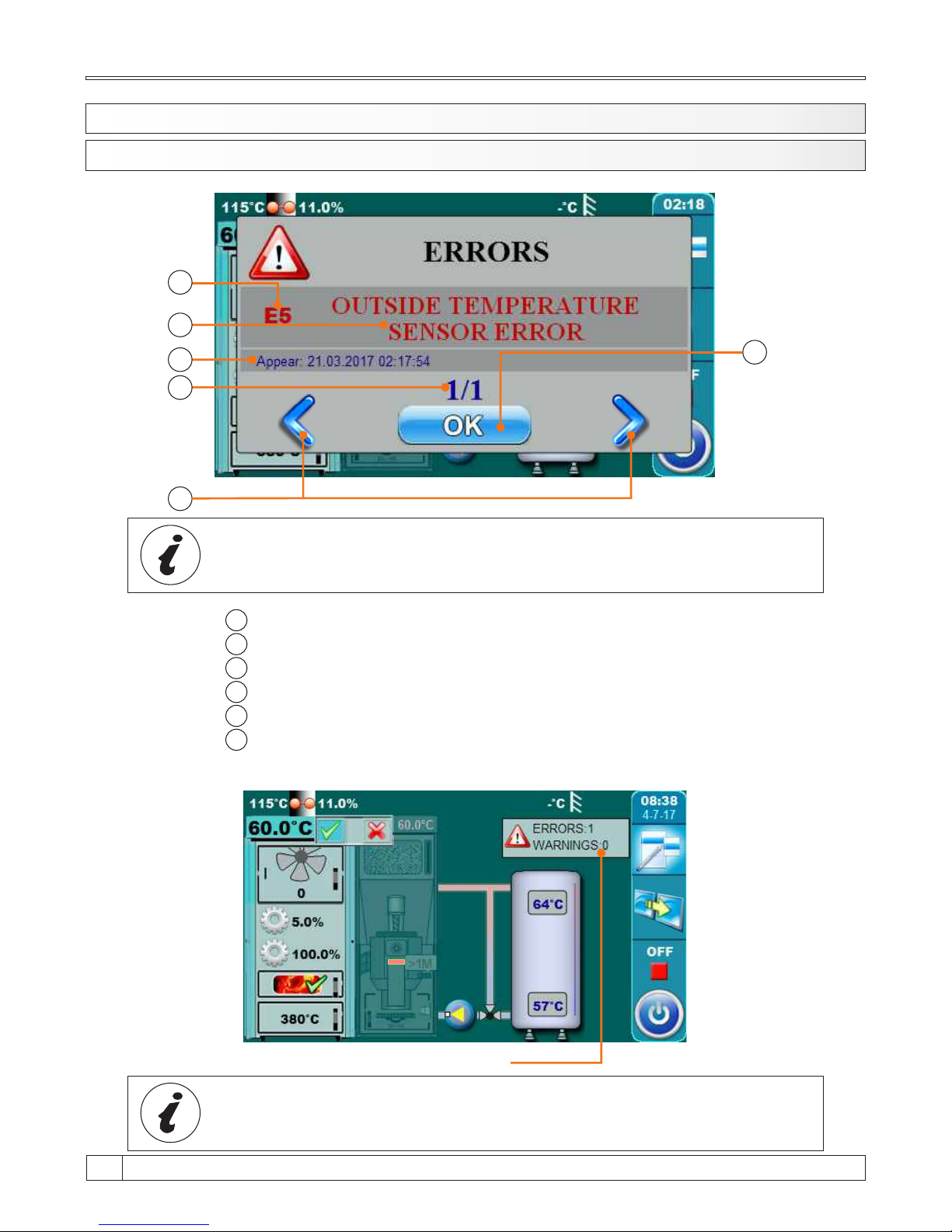
1
2
3
4
5
6
Error / Warning / Information code
Error / Warning / Information name
Date and time of error / warning / information occurrence
Number of errors / warnings / informations
„OK” button
Buttons for scrolling through errors / warning / informations
Minimized window on main display
By pressing „OK” button error window will be minimized and showned on main display.
10.1 ERRORS/WARNINGS/INFORMATIONS ON THE MAIN SCREEN
All errors/warnings are recorded in history (see point 10.2.History)
1
2
3
4
6
5
When the error/warning still present, error/warning name and code
is painted red, and when error/warning is resolved, text turns green
10.0. MALFUNCTIONS
Technical instructions BioTec Plus
76
Page 77
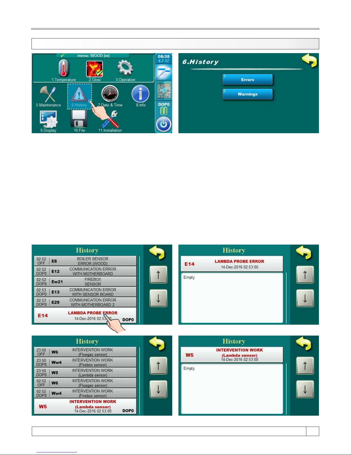
10.2. HISTORY
By pressing on „History” button will be opened menu for choosing history list. It can be choosen
between error list and warning list. Informations history are placed with error list.
Written is:
- time of occurrence errors / warnings / informations
- error / warning / information code
- description of the error / warning / information.
The first press on the field error/warning/information field is indicated, in addition
to see and date generated errors/warnings/information. The second press on the selected error/
warning/information, prints a detailed description of the error/warnings/information and corrective
action errors/warnings/information. If for some error/warning/information there is no description
on current software version, on the screen will be displayed ”empty“.
Errors list
Warnings list
1x
15
77
Technical instructions BioTec Plus
Page 78

10.3. ERROR LIST
MUTUAL ERRORS (WOOD / WOOD PELLETS):
E11
Memory error
Possible causes: Call service man!
ERROR
NAME DESCRIPTION
E1
Boiler status: Boiler go to phases S7, C0 and OFF.
Possible causes:Interruption on el. connections between
sensor and boiler, connection to the boiler, cold
connection or DHW sensor is invalid.
DHW sensor error
E2
Boiler status: Boiler go to phases S7, C0 and OFF.
Possible causes: Interruption on el. connections between
sensor and boiler, cold connection or buffer tank sensor (up)
is invalid.
Buffer tank sensor error
(Up)
E3
Boiler status: Boiler go to phases S7, C0 and OFF.
Possible causes: Interruption on el. connections between
sensor and boiler, cold connection or buffer tank sensor
(down) is invalid.
Buffer tank sensor error
(Down)
E4
Boiler status: Boiler go to phases S7, C0 and OFF.
Possible causes: Interruption on el. connections between
sensor and boiler, cold connection or invalid flue gas
sensor.
Flue gas sensor error
E5
Boiler status: Boiler work normally, problem appears on
work of CM2K regulator if is installed.
Possible causes: Interruption on el. connections between
sensor and boiler (CM2K), cold connection or invalid
outside temperature sensor.
Outside temperature
sensor error
Possible causes: Interruption on el. connections between
sensor and boiler, cold connection or invalid main flow
sensor.
Main flow sensor error
E6
Boiler status: Boiler go to phases S7, C0 and OFF.
Possible causes: Interruption on el. connections between
sensor and boiler, connection to the boiler, cold connection
or invalid return flow sensor.
Return flow sensor error
E7
E8
Boiler status: Boiler go to phases S7, C0 and OFF.
Possible causes: Interruption on el. connections between
sensor and boiler, connection to the boiler, cold connection
or invalid sensor.
Boiler sensor error
(Wood)
E9
Unknown boiler power
Boiler status: Boiler immediate go to phase OFF.
Possible causes: Key for power loading is not installed or
recognized, cold connection or invalid key.
E10
Fan error
Boiler status: Boiler immediate go to phase OFF.
Possible causes: Invalid fan or rpm counter (integrated in
fan housing) or safety thermostat is interrupt el. supply
to fan because of too high temperature in the boiler.
Technical instructions BioTec Plus
78
Page 79

E13
Communication error with
sensor board
Boiler status: Boiler go to phases S7, C0 and OFF.
Possible causes: Call service man!
E14
Lambda probe error
a) Error occurs in the phase of "OFF" The problem is with
el. heater which is integrated into the lambda probe
b) Error occurs in all phases except "OFF”
The problem is with the communication system within
the lambda(Cables, connectors, el. boards, software)
E16
Communication error with
CM2K module (1st and
2nd circuit)
Boiler status: Boiler work normally.
Possible causes:Interruption in el. connections between
boiler and CM2K (between two CM2K’s), connection on
boiler and CM2K (or two adjecent CM2K’s) or CM2K
module is invalid.
E17
Sensor reg. 1. circuit
Boiler status: Pump of 1+ heating circuit doesn't work.
Boiler work normally.
Possible causes: Error on flow temperature sensor of 1+
heating circuit (on regulator CM2K).
E18
Corrector reg. 1. circuit
Boiler status: Pump of 1+ heating circuit work in
intervention mode by heating curve. Boiler work normally.
Possible causes: Error on room corrector of 1+ heating
circuit (CM2K regulator), bad corrector connection to the
CM2K or room corrector failure.
E19
Sensor reg. 2. circuit
Boiler status: Pump of 2+ heating circuit doesn't work.
Boiler work normally.
Possible causes: Error on flow temperature sensor of 2+
heating circuit (on regulator CM2K).
E20
Corrector reg. 2. circuit
Boiler status: Pump of 2+ heating circuit work in
intervention mode by heating curve. Boiler work normally.
Possible causes:
Error on room corrector of 2+ heating circuit (CM2K
regulator), bad corrector connection to the CM2K or room
corrector failure.
E24
Boiler status: Boiler work normally.
Possible causes: Interruption on el. connections between
room corrector and boiler, connection to the boiler or room
corrector is invalid.
Room corrector
E22
Flue gas temperature too
high
Boiler status: Boiler goes to phase „OFF”.
Possible causes: Flue gas tubes are dirty (wood side),
invalid flue gas sensor, bad sealing, open middle boiler door
(wood side).
E12
Communication error with
motherboard
Boiler status: Boiler immediate go to phase OFF.
Possible causes: Call service man!
E26
Boiler status: Boiler work normally.
Intervention mode: Boiler work to content heating demand
but boler has reduced possibilities.
Possible causes: Interruption on el. connections between
firebox sensor and boiler or bad connection to the boiler.
Firebox sensor
disconnected
15
79
Technical instructions BioTec Plus
Page 80

E27
Boiler status: Boiler work normally.
Possible causes: Interruption on el. connections between
room corrector and boiler, connection to the boiler or
hydraulic crossover sensor is invalid.
Hydraulic crossover
sensor error
E16_1
Boiler status: Boiler work normally.
Possible causes:Interruption in el. connections between
boiler and CM2K (between two CM2K’s), connection on
boiler and CM2K (or two adjecent CM2K’s) or CM2K
module is invalid.
Communication error with
CM2K module (3rd and
4th circuit)
E17_1
Sensor reg. 3. circuit
Boiler status: Pump of 3+ heating circuit doesn't work.
Boiler work normally.
Possible causes: Error on flow temperature sensor of 3+
heating circuit (on regulator CM2K).
E18_1
Corrector reg. 3. circuit
Boiler status: Pump of 3+ heating circuit work in
intervention mode by heating curve. Boiler work normally.
Possible causes:
Error on room corrector of 3+ heating circuit (CM2K
regulator), bad corrector connection to the CM2K or room
corrector failure.
E19_1
Sensor reg. 4. circuit
Boiler status: Pump of 4+ heating circuit doesn't work.
Boiler work normally.
Possible causes: Error on flow temperature sensor of 4+
heating circuit (on regulator CM2K).
E20_1
Corrector reg. 4. circuit
Boiler status: Pump of 4+ heating circuit work in
intervention mode by heating curve. Boiler work normally.
Possible causes:
Error on room corrector of 4+ heating circuit (CM2K
regulator), bad corrector connection to the CM2K or room
corrector failure.
E16_2
Boiler status: Boiler work normally.
Possible causes:Interruption in el. connections between
boiler and CM2K (between two CM2K’s), connection on
boiler and CM2K (or two adjecent CM2K’s) or CM2K
module is invalid.
Communication error with
CM2K module (5rd and
6th circuit)
E17_2
Sensor reg. 5. circuit
Boiler status: Pump of 5+ heating circuit doesn't work.
Boiler work normally.
Possible causes: Error on flow temperature sensor of 5+
heating circuit (on regulator CM2K).
E19_2
Sensor reg. 6. circuit
Boiler status: Pump of 6+ heating circuit doesn't work.
Boiler work normally.
Possible causes: Error on flow temperature sensor of 6+
heating circuit (on regulator CM2K).
E18_2
Corrector reg. 5. circuit
Boiler status: Pump of 5+ heating circuit work in
intervention mode by heating curve. Boiler work normally.
Possible causes:
Error on room corrector of 5+ heating circuit (CM2K
regulator), bad corrector connection to the CM2K or room
corrector failure.
Technical instructions BioTec Plus
80
Page 81

E20_2
Corrector reg. 6. circuit
Boiler status: Pump of 6+ heating circuit work in
intervention mode by heating curve. Boiler work normally.
Possible causes:
Error on room corrector of 6+ heating circuit (CM2K
regulator), bad corrector connection to the CM2K or room
corrector failure.
E16_3
Boiler status: Boiler work normally.
Possible causes:Interruption in el. connections between
boiler and CM2K (between two CM2K’s), connection on
boiler and CM2K (or two adjecent CM2K’s) or CM2K
module is invalid.
Communication error with
CM2K module (7rd and
8th circuit)
E17_3
Sensor reg. 7. circuit
Boiler status: Pump of 7+ heating circuit doesn't work.
Boiler work normally.
Possible causes: Error on flow temperature sensor of 7+
heating circuit (on regulator CM2K).
E18_3
Corrector reg. 7. circuit
Boiler status: Pump of 7+ heating circuit work in
intervention mode by heating curve. Boiler work normally.
Possible causes:
Error on room corrector of 7+ heating circuit (CM2K
regulator), bad corrector connection to the CM2K or room
corrector failure.
E19_3
Sensor reg. 8. circuit
Boiler status: Pump of 8+ heating circuit doesn't work.
Boiler work normally.
Possible causes: Error on flow temperature sensor of 8+
heating circuit (on regulator CM2K).
E20_3
Corrector reg. 8. circuit
Boiler status: Pump of 8+ heating circuit work in
intervention mode by heating curve. Boiler work normally.
Possible causes:
Error on room corrector of 8+ heating circuit (CM2K
regulator), bad corrector connection to the CM2K or room
corrector failure.
E28
Communication error with
CMGSM
Boiler status: Boiler work normally.
Possible causes: Interruption in el. connections between
boiler and CMGSM or invalid CMGSM module.
E29
Communication error with
motherboard 2
Boiler status: Boiler goes to phase „OFF”.
Possible causes: Call service man!
15
81
Technical instructions BioTec Plus
Page 82

WOOD FIRING ERRORS:
ERROR
NAME DESCRIPTION
Ew21
Firebox sensor
Boiler status: Boiler work normally.
Intervention mode: Boiler work to content heating demand
but boiler has reduced possibilities.
Possible causes: Invalid firebox sensor.
WOOD PELLETS FIRING ERRORS:
Ep31
Photocell error
Ep32
Safety pressure switch
Ep33
No flame in ignition phase
Ep34
Flame disappeared
working phase
Ep35
Error grate cleaner
Ep36
Fuel level
Ep37
Flame disappeared at
ignition stage
ERROR
NAME DESCRIPTION
Boiler status: Boiler go to phase OFF after ending phase
S0 (retry start is allowed).
Possible cause: Invalid photocell (sending information
that flame exist in phase S0).
Boiler status: Boiler immediate go to phase OFF.
Possible causes: Firebox resistance is too high in phases
S2, S3, S4, (S5). It’s open any door or opening on boiler.
Interruption in el. connection between safety pressure
switch and boiler, connection to the boiler, cold connection
or invalid safety pressure switch. Interruption or bad sealing
of safety pressure switch pipe.
Boiler status: Boiler immediate go to phase OFF.
Boiler status: Boiler immediate go to phase OFF.
Boiler status: Boiler immediate go to phase OFF.
Boiler status: Boiler go to phases S7, C0 and OFF.
Boiler status: Boiler immediate go to phase OFF.
Ep38
Flame disappeared
stabilization stage
Ep39
Fuel sensor
Boiler status: Boiler immediate go to phase OFF.
Boiler status: Boiler immediate go to phase OFF.
Ep40
Error flap not closed
Boiler status: Boiler work normally.
Possible causes: Check if the flap is blocked with pellets , if
the sensor is soiled with dust , if the sensor is about 1 mm
distant from the flap , if the sensor reacts on the flap ( the
LED lamp is switching on the sensor ).
Technical instructions BioTec Plus
82
Page 83

Ep41
No pellets
Ep42
Mole or screw not working
Ep43
Communication error with
CMVAC
Ep45
Wood in firebox or
incorrect adjustment of
pellet side.
Ep46
Upper door opened wood side
Ep44
Boiler sensor error (pellet)
Boiler status: Boiler work normally.
Possible causes: Check the pellet level in the big
tank/room , check if the flexible tubes are blocked, check if
the turbine net is full with dust.
Boiler status: Boiler work normally.
Possible causes: Check the electric connections on the
mole/feeder screw, check the filthiness of the mole/feeder
screw.
Boiler status: Boiler work normally.
Possible causes:Check the UTP cable and its connections
with the electric boards.
Boiler status: Boiler go to phases S7, C0 and OFF.
Possible causes: Interruption on el. connections between
sensor and boiler, connection to the boiler, cold connection
or invalid sensor.
Boiler status: Boiler go to phases S7, C0 and OFF.
Possible causes: Existing of larger quantity of wood in
firebox (wood side) during burner work (wood pellet side) or
incorrect adjustment of pellet side.
Boiler status: Boiler go to phases S7, C0 and OFF.
Possible causes: Upper boiler door are opened (wood
side) during burner work (wood pellet side) after warning
time Wp15 expire, invalid microswitch - upper boiler door
(wood side).
Ep47
Screw refill
Boiler status: Boiler work normally.
Possible causes: No pellets in CPSP-BP tank for refilling,
problem with feeder screw in CPSP-BP, interruption on el.
connection between boiler and feeder screw, connection to
the boiler.
15
83
Technical instructions BioTec Plus
Page 84

10.4. WARNING LIST
MUTUAL WARNINGS (WOOD / WOOD PELLETS):
Factory settings loaded.
WARNING
NAME DESCRIPTION
Appear always when fan decrease rotating speed or if
turning ”OFF“ itself because of high flue gas temperature.
The boiler operates without using the lambda probe.
The boiler operates without using the flue gas sensor.
It can occur only if the configuration contain ”Protection
valve”. The boiler will resume normal work (the cause
should be removed because boiler condensation will occur
and flue passes will clog up). The problem may be with 3way mixing valve (protection valve) / motor drive / sensor of
return flow temperature.
The temperature accumulation tank is lower than the
desired which allow pump work.
W1
Factory setting loaded
W3
W5
W6
W10
W12
Fan protection
Intervention work
(Lambda sensor)
Intervention work
(Flue gas sensor)
Low return temperature
Low buffer temperature
WOOD FIRING WARNINGS:
WARNING
NAME DESCRIPTION
Boiler working (wood side), upper boiler door is opened and
flue gas temperature is too high. It’s necessary to close
upper boiler door.
The boiler operates without using the RPM (rotates per
minute) sensor.
Bad ignition, too damp wood, non-closed middle or lower
door, non-closed side covers for cleaning or rear top cover
for cleaning), impassable flue pipe from the fan to the
chimney, blocked passes for the primary or secondary air
between the upper and middle boiler door. Check and close
the insufficiently sealed openings and if necessary fill and
start the boiler again, if you don’t help these actions, call an
authorized service to check primary / secondary openings.
Ww2
Ww7
Ww8
Flue gas temperature
high. Close the upper
door!
Intervention work
(RPM sensor)
Ignition error
The boiler operates without using the firebox sensor.
W4
Intervention work
(Firebox sensor)
Technical instructions BioTec Plus
84
Page 85

WOOD PELLETS FIRING WARNINGS:
WARNING
NAME DESCRIPTION
Boiler status: Boiler will be work for a while, if pellet tank
don’t be refilled with pellets will be shown „E22 Fuel level”
what’s mean that is no enough fuel for continue of boiler
work.
Possible causes: Low fuel level in pellet tank, enough for
short time.
Wp13
Fuel level
Upper boiler door are opened (wood side) during burner
work (wood pellet side), if time counter expire then will be
showned error Ep46.
Wp15
Upper door opened wood side
Too high flue gas temperature with the open upper boiler
door. Close the uper door and restart the boiler (load fuel if is
necessary).
No fuel.
Ww9
Ww11
Fan is OFF, flue gas
temperature is to high.
Close the upper door!
Out of fuel
15
85
Technical instructions BioTec Plus
Page 86

10.5. INFORMATION LIST
MUTUAL INFORMATIONS (WOOD / WOOD PELLETS):
INFO.
NAME
I5
Power up
(Power down)
WOOD FIRING INFORMATIONS:
INFO.
NAME
Iw1
Off during ignition
Iw2
Ignition automaticly
proceeded
Iw3
Bad ignition
Iw4
Off during stabilization
Iw6
Glow after power up
Iw7
Off after power up
WOOD PELLETS FIRING INFORMATIONS:
INFO.
NAME
Ip8
Refill
Ip9
Flame disappeared in
ignition phase
Ip9_1
Retry ignition
Ip10
No flame in stabilization
stage
Ip10_1
Retry ignition
Ip11
Pellet supply tube
temperature too high
Ip12
Flame disappeared
working phase
Ip12_1
Retry ignition
Technical instructions BioTec Plus
86
Page 87

15
87
Technical instructions BioTec Plus
Page 88
HEATING TECHNIQUE
www.centrometal.hr
e-mail: [email protected]
Centrometal d.o.o. Glavna 12, 40306 Macinec, Croatia
central tel: +385 40 372 600, fax: +385 40 372 611
service tel: +385 40 372 622, fax: +385 40 372 621
Company assumes no responsibility for possible inaccuracies in this book originated typographical errors or rewriting, all the pictures and diagrams are principal and it is necessary to adjust each actual
situation on the field, in any case the company reserves the right to enter their own products such modifications as considered necessary.
 Loading...