

Page 1
TURBT-L-02-2015 - v2.35L- eng
BioTec-L
Centrometal d.o.o. - Glavna 12, 40306 Macinec, Croatia, tel: +385 40 372 600, fax: +385 40 372 611
HEATING TECHNIQUE
Technical instructions
using REGULATION of
hot water boiler BioTec-L
THE FIRST START-UP MUST BE DONE BY AUTHORIZED PERSON
OTHERWISE PRODUCT WARRANTY IS NOT VALID
English
Deutsch
Magyar
v2.35L xxkW
Italiano
Français Portugues
Čeština
SrpskiSlovenski
Hrvatski
Nederlands
Espanol
Page 2
English
Deutsch
Magyar
v2.35L xxkW
Italiano
Français Portugues
Čeština
SrpskiSlovenski
Hrvatski
Nederlands
Espanol
Technical instructions REGULATION BioTec-L
2
Screen
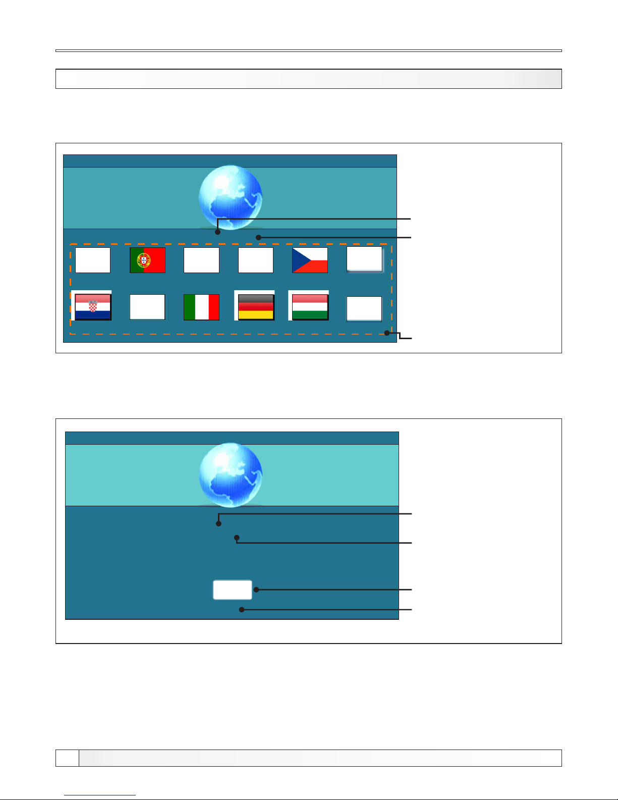
After turning on the main switch, screen will display language selection menu and software version.
To select the language, press the flag of language you want.
Software version
Language selection
SWITCHING ON
If the language selection is "disabled" (display > language sel > disabled), initial message wil appear
in the screen as long as the set in the menu "Welcome time" (display > welcome time).
Boiler power
(25, 34, 45 kW)
v2.35 L XX kW
5
Button’’OK’’
Initial message duration
(countdown)
Software version
Boiler power
(25, 34, 45 kW)
Page 3
Technical instructions REGULATION BioTec-L
3
Main Menu, Buttons
MAIN MENU
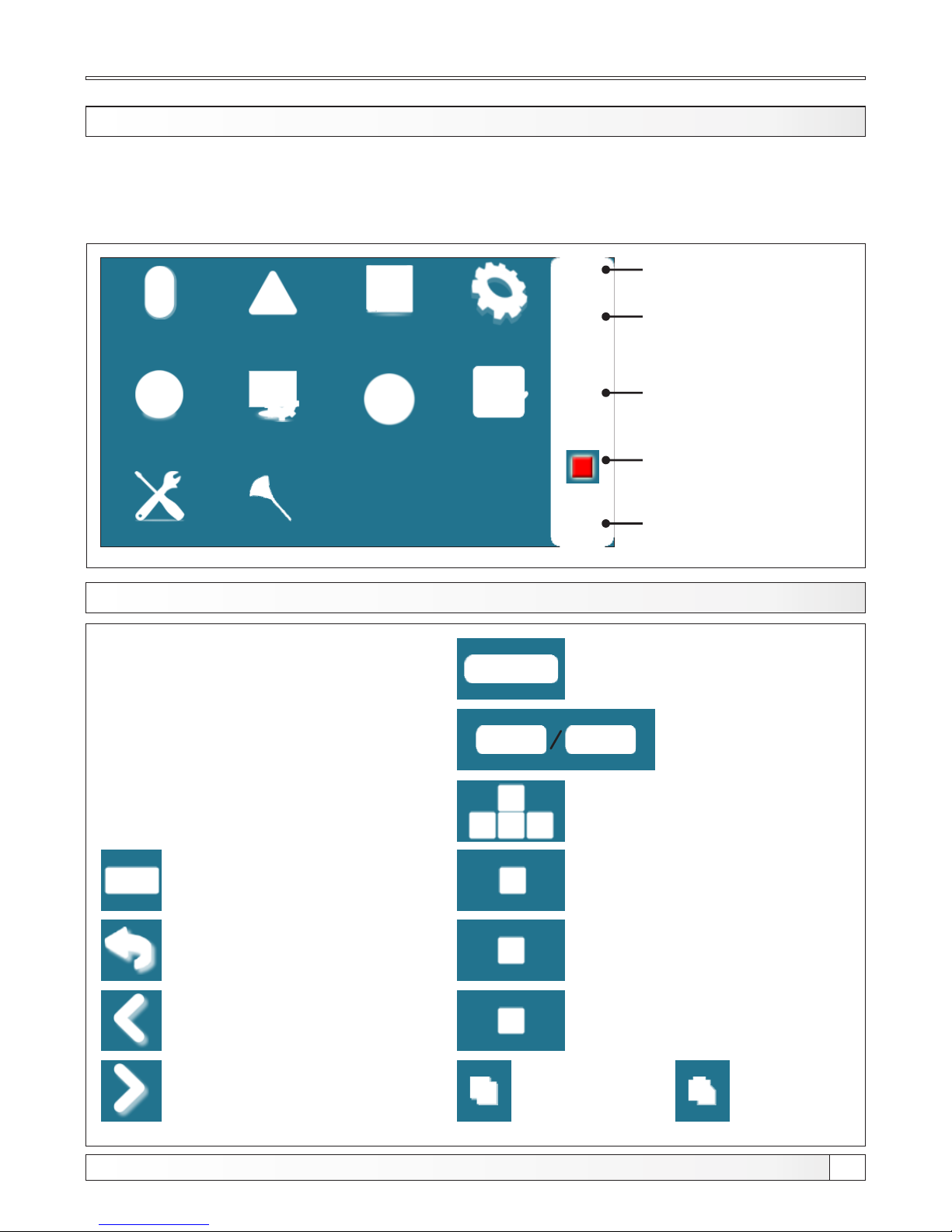
The main menu is used to select the desired submenu. To select a specific menu you must press the
appropriate icon on the screen. To switch between the ’’Main menu’’ and ’’Boiler working display’’
press the button ’’Display selection’’. To switch between graphic and numeric display of the boiler
using press ’’Boiler operation display’’.
Operation
Installation
Temperature
History
Date & Time Display
Info
File
02:11
Start/stop boiler
State of the current
boiler status
OFF
Time
Display selection:
Main menu / work
Boiler operation display :
graphic / numeric
BUTTONS
Button ’’START’’/’’STOP’’
Button ’’ON / OFF’’
options: on / off boiler operation’’
Button ’’DISPLAY SELECTION’’
options: main menu / work
Button ’’BOILER OPERATION DISPLAY’’
options: graphic / numeric
Button ’’ENTER’’
Button ’’BACK’’
Button’’PREVIOUS SCREEN’’
Button ’’NEXT SCREEN’’
Button ’’OK’’
Navigation buttons:
’’LEFT’’, ’’RIGHT’’, ’’UP’’, ’’DOWN’’
Button ’’DELETE’’
Button ’’FACTORY SETTINGS’’
Button ’’INFORMATION’’
Button ’’COPY’’ Button ’’PASTE’’
Glow
Cleaning
Page 4
Screen, Symbols
SYMBOLS
05:08
OFF
0
0.0%
0.0%
xx°C
x%xx°C
xx°C
xx°C
xx°C
1
3 4 2
5
7
8
9
10
11
12 14
6
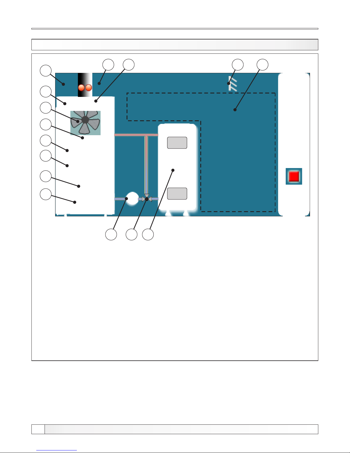
1 - Boiler BioTec-L
2 - Buffer tank
3 - Boiler pump P1
4 - 3-way thermic valve or
3-way mixing valve with
motor drive (protection valve)
5 - Symbol of fan operation
(when working, symbol is turning)
6 - Fan speed (rpm)
7 - Curent position of primary air
actuator
8 - Current position of secondary air
actuator
9 - Combustion chamber temperature
10 - Flue gas temperature sensor
11 - The percentage of oxygen in the flue gases
12 - Outer temperature sensor
13 - Glow indicator (if enabled)
14 - The symbol in this section depend ont the
selected configuration
15 - Boiler temperature
13
xx °C
15
Technical instructions REGULATION BioTec-L
4
Page 5
Configuration
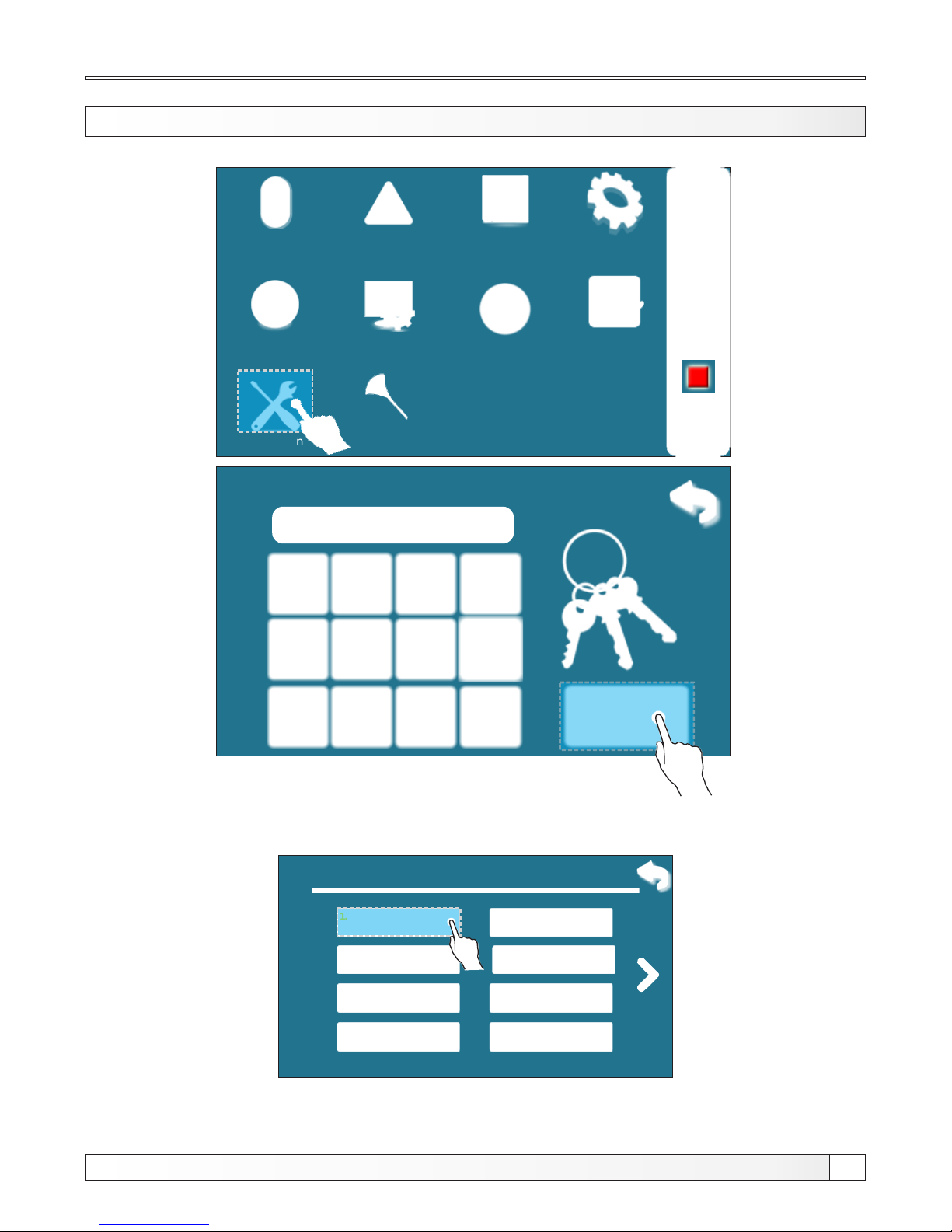
CONFIGURATION (authorized persons only)
Operation
Installation
Temperature
History
Date & Time Display
Info
File
02:11
OFF
Glow
Enter PIN
* * * *
For entry into Configuration menu press ”Installation“ button. When you press ”Installation“ button
control unit ask for pin. Enter pin and confirm it by presing “Enter“ button.
9. Installation
In installation menu press ”Configuration“ button to enter into «Configuration» menu.
Cleaning
Technical instructions REGULATION BioTec-L
5
Stabilization
Lambda probe
Temperature
Power D4
Power D3
Power D2
Power D1
8.
7.
6.
5.
4.
3.
2.
1.
Configuration
Page 6
9.1.1. Configuration
Corrector
Room thermo.Floor h.
Radiator h.
9.1.1. Configuration
Protection valve
Motor drive
DHW
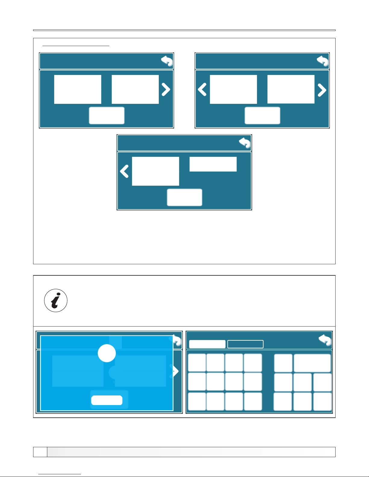
Configuration menu:
Configure the system by selecting installed components! Some components exclude others
(eg. you can choose radiator heating or floor heating, not both of them), some components
can be selected only with another component (eg. room thermostat can be selected only if
you select radiator h. or floor h., if you don't select this component room thermostat can't be
selected).
Configuration
2.Heating Cir.
9.1.1. Configuration
2.Circ. Room t.
Protection valve
2.Heating Cir.
Technical instructions REGULATION BioTec-L
6
When the configuration contains motor drive, you need to enter VALVE TIME.
This parameter defines how many seconds is required for mixing valve
opening/closing.
THIS NUMBER MUST CORRESPOND EXACTLY TO THE TIME IT TAKES THE
MOTOR DRIVE TO OPEN THE VALVE (DEPENDS ON THE TYPE OF MOTOR)
Valve time
120
120 sec
9.1.1. Configuration
Corrector
Room thermo.Floor h.
Radiator h.
Info
File
Choosing this configuration, you
should set 3-way valve time!
Page 7
Configuration 1: (Basic configuration)
9.1.1. Configuration
Corrector
Room thermo.Floor h.
Radiator h.
9.1.1. Configuration
Protection valve
Motor drive
DHW
On display is displayed:
05:08
OFF
0
0.0%
0.0%
xx°C
x%xx°C
xx°C
xx°C
xx°C
2
xx °C
1
3
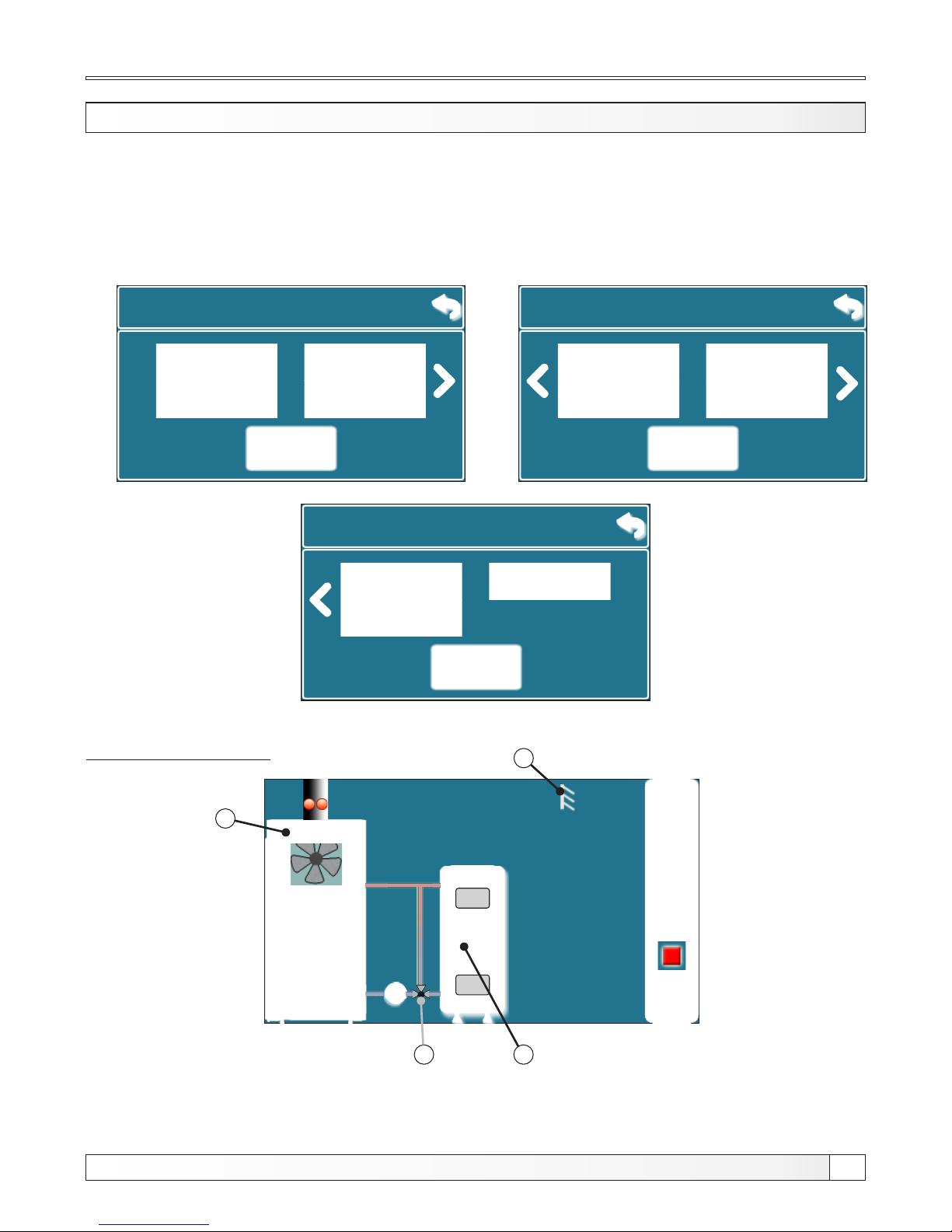
1 - Boiler BioTec-L
2 - Buffer tank
3 - Outer temperature sensor
4 - Return flow protection by 3-way termostatic valve (60°C)
VTC 531 (60°C), LTC 141 (60°C) or laddomat 21 (63°C)
Configuration 1
On this configuration all compontents are unselected.
4
2.Heating Cir.
9.1.1. Configuration
2.Circ. Room t.
Protection valve
2.Heating Cir.
Technical instructions REGULATION BioTec-L
7
GENERAL CONNECTION SCHEMES CONFIGURATION
In ”Tecnical instructions for installation of hot water boiler BioTec-L” are showned general
connection schemes.
Page 8
Configuration 2
Technical instructions REGULATION BioTec-L
8
On display is displayed:
05:08
OFF
0
0.0%
0.0%
xx°C
x%xx°C
xx°C
xx°C
xx°C
2
xx °C
1
3
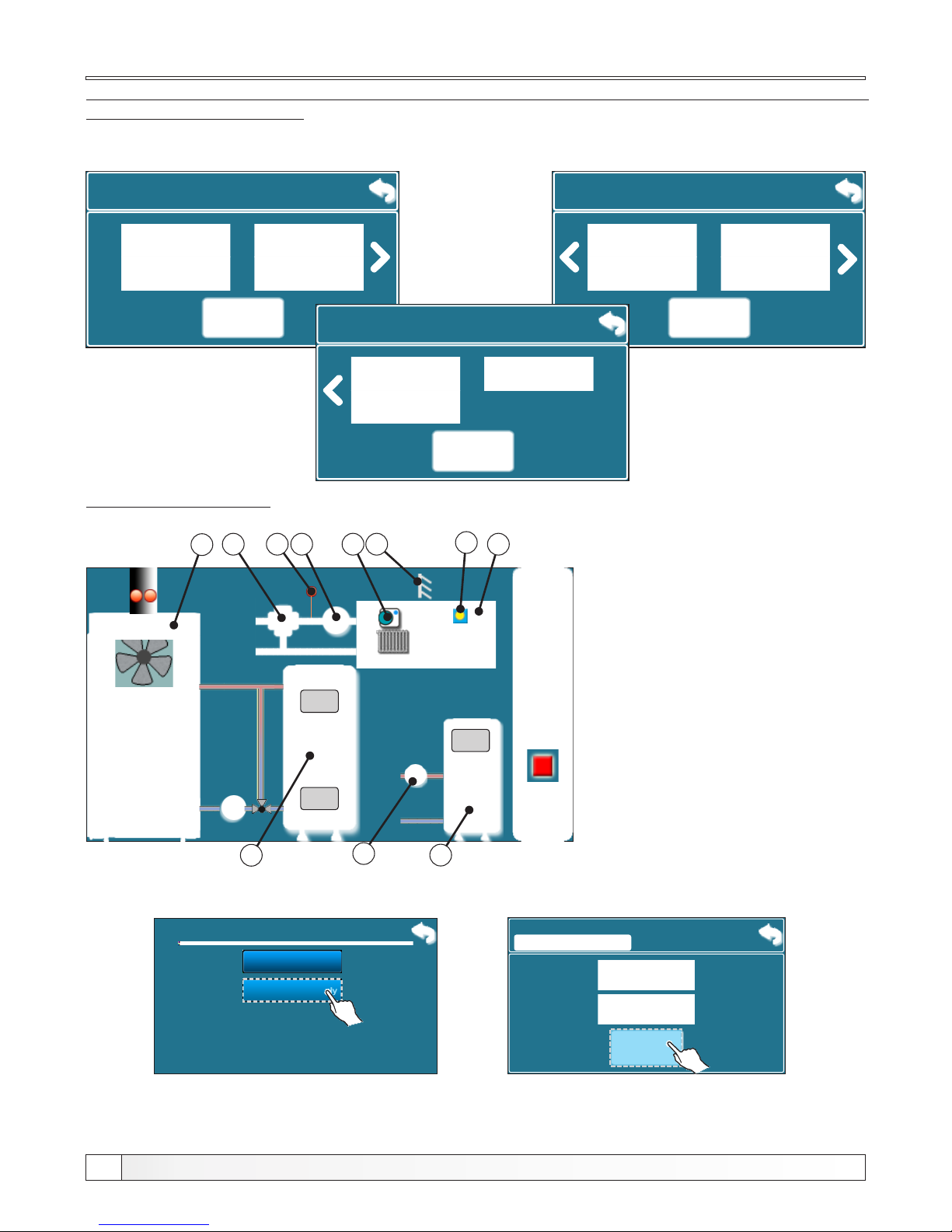
Configuration 2 is from scheme 4 and scheme 5 from ”Tecnical instructions for installation of
hot water boiler BioTec-L”
25.0°C
20.0-0.0°C
20.0°C
-°C
8
5 4
67
xx°C
9
10
1 - Boiler BioTec-L
2 - Buffer tank
3 - Outer temperature sensor
4 - Heating etage (radiator h.)
5 - Room corrector
6 - Heating pump P3
7 - Main flow sensor
8 - Mixing valve with el. actuator
of heating circuit (motor drive)
9 - DHW boiler
10 - DHW pump P2
11 - Day/night temperature
indicator
In this configuration the following components are selected:
- radiator heating, corrector, motor drive (heating circuit), DHW (domestic hot water)
11
9.1.1. Configuration
Room thermo.Floor h.
9.1.1. Configuration
DHW
9.1.1. Configuration
2.Circ. Room t.
2.Heating Cir.
2.Heating Cir.
Motor drive Protection valve
Protection valve
CorrectorRadiator h.
9.1.2. Pump DHW continously
ON
factory:
OFF
OFF
ON
9.1 Configuration
Configuration
Pump DHW continously
1.
2.
When DHW sensor (ERROR 1) occurs, regulation cannot automatically turn ”ON/OFF“ DHW pump.
For intervention work serviceman can turn ”ON“/“OFF“ DHW pump manually. In this case, the pump
DHW work all the time until serviceman manually turn it ”OFF“.
In this configuration, on the previous screen, a new button is displayed (Pump DHW continously)
Page 9
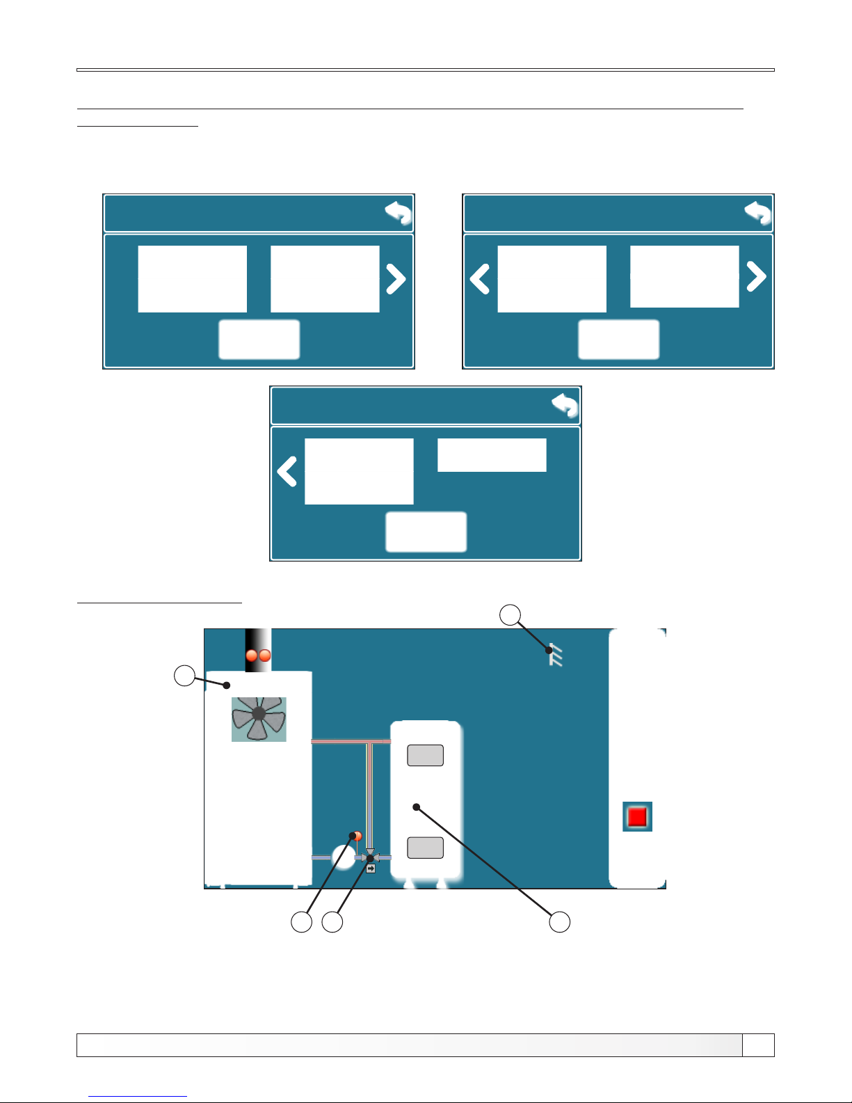
On display is displayed:
05:08
OFF
0
0.0%
0.0%
x%xx°C
xx°C
xx°C
xx°C
2
xx °C
1
9.1.1. Configuration
Room thermo.Floor h.
9.1.1. Configuration
Radiator h.
Corrector Motor drive
DHW
Protection valve
-°C
4
5
xx°C
3
1 - Boiler BioTec-L
2 - Buffer tank
3 - Outer temperature sensor
4 - Mixing valve with el. actuator
(return flow protection) (protection valve)
5 - Return flow sensor
Configuration 3
Configuration 3 is from scheme 6 from ”Tecnical instructions for installation of hot water
boiler BioTec-L”
In this configuration the following components are selected: - protection valve (return flow protection)
2.Heating Cir.
9.1.1. Configuration
2.Circ. Room t.
2.Heating Cir.
Protection valve
Technical instructions REGULATION BioTec-L
9
Page 10
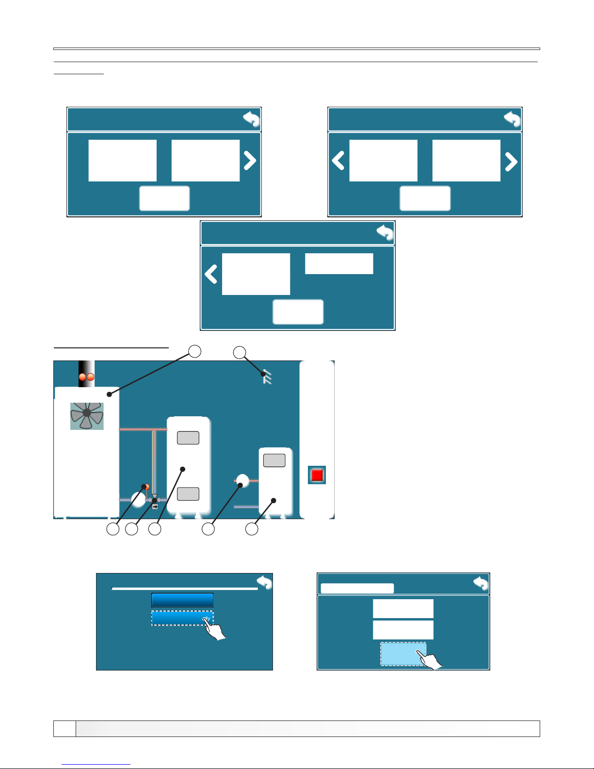
Configuration 4
Technical instructions REGULATION BioTec-L
10
On display is displayed:
9.1.1. Configuration
Room thermo.Floor h.
9.1.1. Configuration
Radiator h. Corrector Motor drive Protection valve
1 - Boiler BioTec-L
2 - Buffer tank
3 - Outer temperature sensor
4 - Mixing valve with
el. actuator
(return flow protection)
(protection valve)
5 - Return flow sensor
6 - DHW tank
7 - DHW pump
DHW
05:08
OFF
0
0.0%
0.0%
x%xx°C
xx°C
xx°C
xx°C
2
xx °C
1
-°C
4
5
xx°C
3
xx°C
67
Configuration 4 is from scheme 7 from ”Tecnical instructions for installation of hot water boiler
BioTec-L”
In this configuration the following components are selected: - protection valve (return flow protection)
- DHW (domestic hot water)
9.1.1. Configuration
2.Circ. Room t.
2.Heating Cir.
Protection valve
2.Heating Cir.
9.1.2. Pump DHW continously
ON
factory:
OFF
OFF
ON
9.1 Configuration
Configuration
Pump DHW continously
1.
2.
When DHW sensor (ERROR 1) occurs, regulation cannot automatically turn ”ON/OFF“ DHW pump.
For intervention work serviceman can turn ”ON“/“OFF“ DHW pump manually. In this case, the pump
DHW work all the time until serviceman manually turn it ”OFF“.
In this configuration, on the previous screen, a new button is displayed (Pump DHW continously)
Page 11
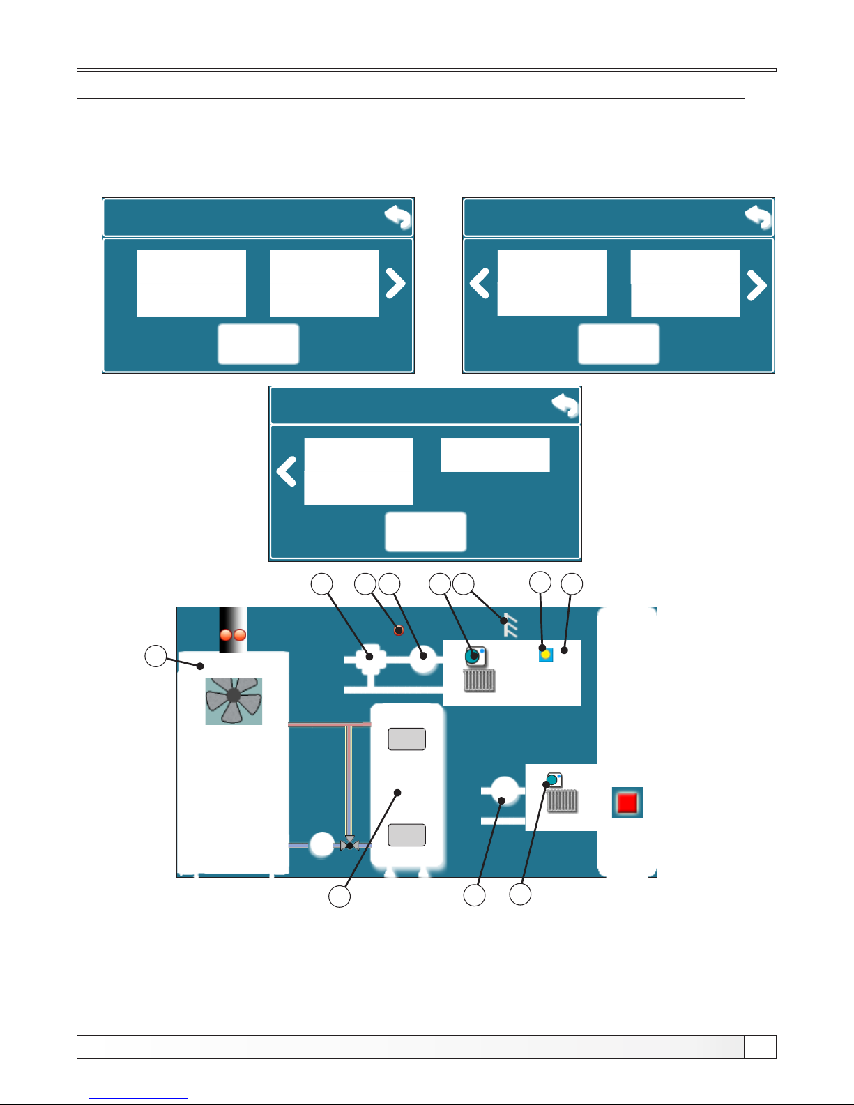
Configuration 5
Configuration 5 is from scheme 8 and 9 from ”Tecnical instructions for installation of hot
water boiler BioTec-L”.
9.1.1. Configuration
Room thermo.Floor h.
9.1.1. Configuration
Radiator h.
Corrector Motor drive Protection valve
In this configuration the following components are selected: radiator heating, corrector
motor drive (heating circuit), 2.Heating Circuit, 2.Circuit room thermostat
9.1.1. Configuration
Protection valve
2.Heating Cir.
On display is displayed:
05:08
OFF
0
0.0%
0.0%
xx°C
x%xx°C
xx°C
xx°C
xx°C
2
xx °C
1
3
25.0°C
20.0-0.0°C
20.0°C
-°C
8
5 4
67
1 - Boiler BioTec-L
2 - Buffer tank
3 - Outer temperature sensor
4 - Heating etage (radiator h.)
5 - Room corrector
6 - Heating pump P3 (circuit 1)
7 - Main flow sensor
8 - Mixing valve with
el. actuator of heating
circuit (motor drive)
DHW
2.Circ. Room t.
2.Heating Cir.
9
10
Technical instructions REGULATION BioTec-L
11
11
9 - Heating pump
(circuit 2)
10 - Room thermostat
(circuit 2)
11 - Day/night temperature
indicator
Page 12
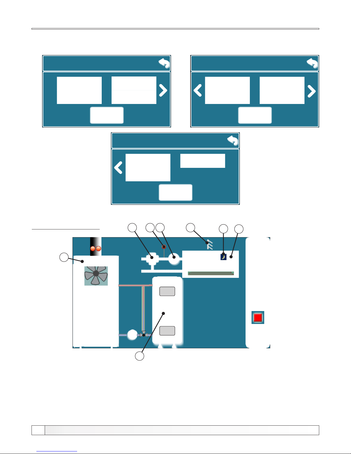
Configuration 6
Technical instructions REGULATION BioTec-L
12
On display is displayed:
02:08
OFF
0
0.0%
0.0%
xx°C
x%xx°C
xx°C
xx°C
xx°C
2
xx °C
1
3
9.1.1. Configuration
Room thermo.
9.1.1. Configuration
Radiator h.
Motor drive Protection valve
20.0°C
-°C
8
4
67
1 - Boiler BioTec-L
2 - Buffer tank
3 - Outer temperature sensor
4 - Heating etage (floor h.)
5 - Day/night temperature
indicator
6 - Heating pump P3
7 - Main flow temperature sensor
8 - Mixing valve with el. actuator
of heating circuit (motor drive)
In this configuration the following components are selected: - floor heating
- motor drive (heating circuit)
9.1.1. Configuration
2.Circ. Room t.
Protection valve
2.Heating Cir.
2.Heating Cir.
Floor h.
Corrector
DHW
5
Page 13
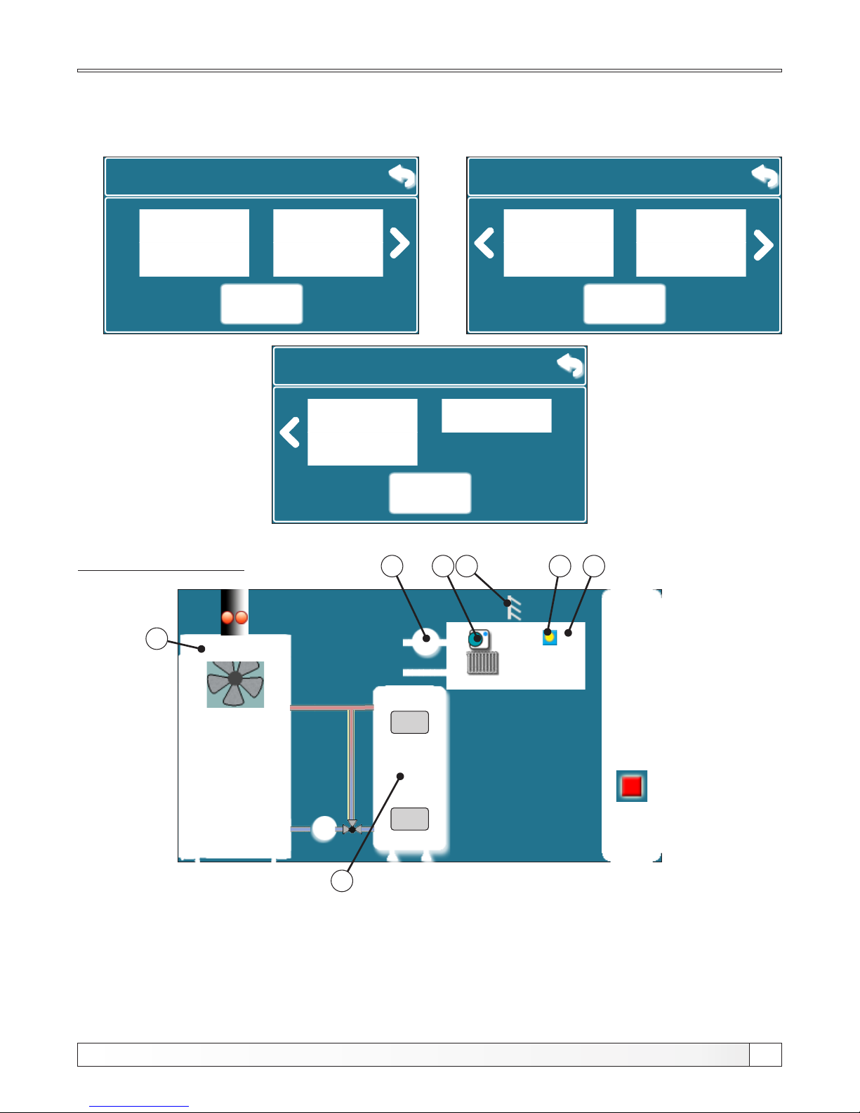
Configuration 7
On display is displayed:
05:08
OFF
0
0.0%
0.0%
xx°C
x%xx°C
xx°C
xx°C
xx°C
2
xx °C
1
3
9.1.1. Configuration
Room thermo.Floor h.
9.1.1. Configuration
Radiator h.
Corrector Protection valve
25.0°C
20.0-0.0°C
5 4
6
1 - Boiler BioTec-L
2 - Buffer tank
3 - Outer temperature sensor
4 - Heating etage (radiator h.)
5 - Room corrector
6 - Heating pump P3
7 - Day/night temperature indicator
In this configuration the following components are selected: - radiator heating
- room corrector
9.1.1. Configuration
2.Circ. Room t.
Protection valve
2.Heating Cir.
2.Heating Cir.
Motor drive
DHW
7
Technical instructions REGULATION BioTec-L
13
Page 14
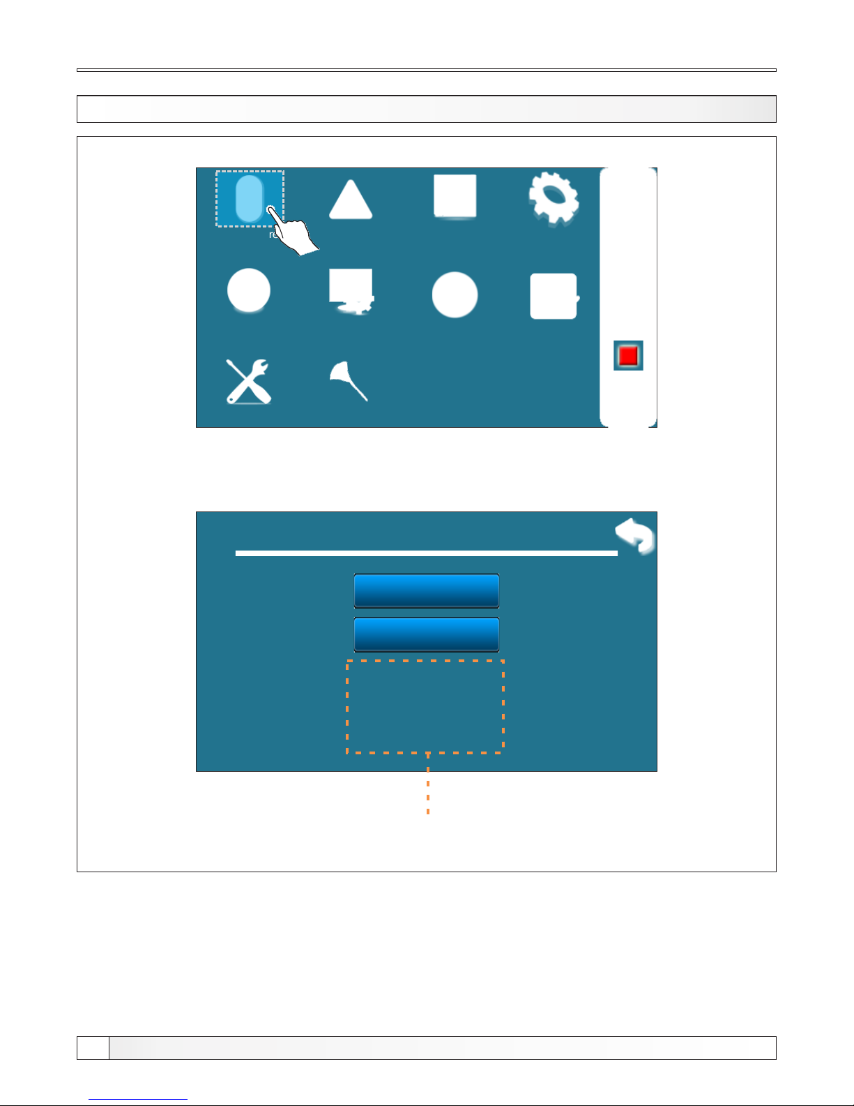
1. TEMPERATURES
Operation
Installation
Temperature
History
Date & Time Display
Info
File
02:11
OFF
Glow
To enter in Temperature menu press ”Temperature“ button. Content of this menu
depends on selected configuration.
1. Temperature
Diff. Boiler
2.
Boiler temp.
1.
Temperatures
Cleaning
Items located within this framework depends on the selected configuration
Technical instructions REGULATION BioTec-L
14
Page 15
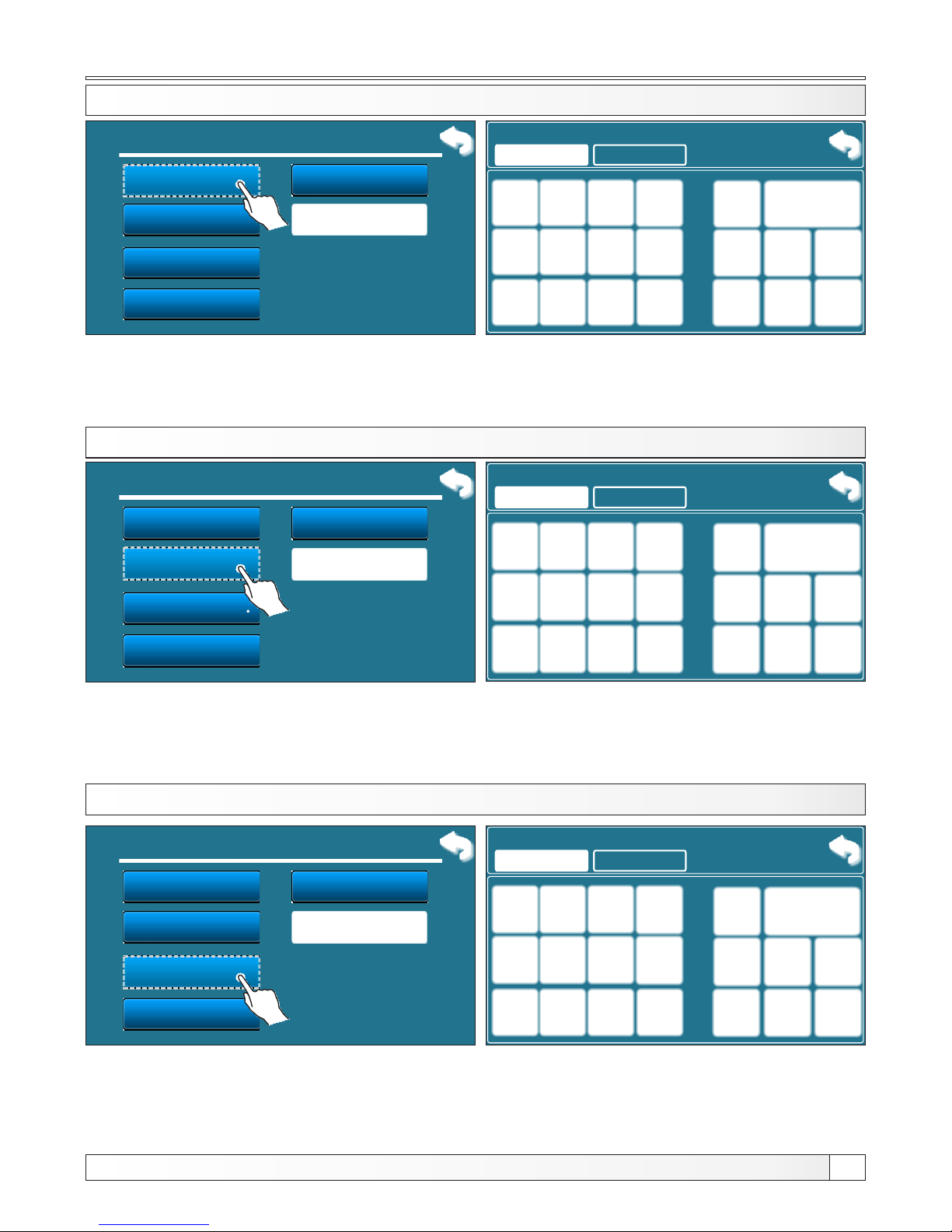
Temperatures
1.1 BOILER TEMPERATURE
Boiler temp.
Diff. Boiler
DHW temp.
Min buf.tank temp.
1. Temperature
1.
2.
3.
4.
5.
Differential of DHW
6.
Heating circuit M.D
1.1 Boiler temp.
85
85
Possible selection: - factory: 85 °C
- Minimum: 75 °C
- Maxsimum: 90 °C
The possibility of setting boiler working temperature
1.2 DIFFERENTIAL OF BOILER TEMPERATURE
Boiler temp.
Diff. Boiler
DHW temp.
Min buf.tank temp.
1.
2.
3.
4.
5.
Differential of DHW
6.
Heating circuit M.D
1.2 Diff. Boiler
5
5
Possible selection: - factory: 5 °C
- Minimum: 5 °C
- Maxsimum: 7 °C
The possibility of setting differential of boiler temperature.
1.3 MINIMUM BUFFER TANK TEMPERATURE
Boiler temp.
Diff. Boiler
DHW temp.
Min buf.tank temp.
1.
2.
3.
4.
5.
Differential of DHW
6.
Heating circuit M.D
1.3. Min buf.tank temp.
20
20
Possible selection: - factory: 20 °C
- Minimum: 5 °C
- Maxsimum: 64 °C
The possibility of setting minimum buffer tank temperature
1. Temperature
1. Temperature
°C
°C
°C
Technical instructions REGULATION BioTec-L
15
Page 16
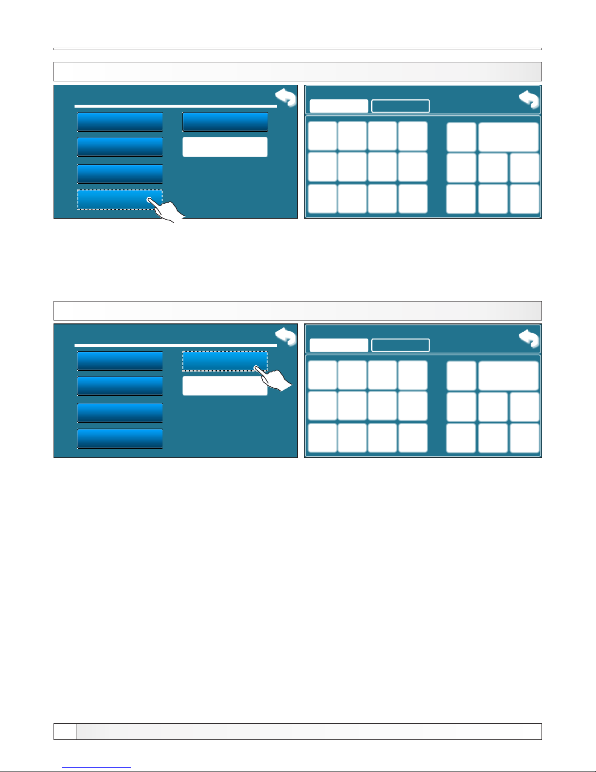
Temperatures
1.4 DOMESTIC HOT WATER TEMPERATURE
Boiler temp.
Diff. Boiler
DHW temp.
Min buf.tank temp.
1.
2.
3.
4.
5.
Differential of DHW
6.
Heating circuit M.D
1.4 DHW temp.
50
50 °C
Possible selection: - factory: 50 °C
- Minimum: 40 °C
- Maxsimum: 80 °C
The possibility of setting domestic hot water temperature.
1. Temperature
1.5 DOMESTIC HOT WATER DIFFERENCE
Boiler temp.
Diff. Boiler
DHW temp.
Min buf.tank temp.
1.
2.
3.
4.
5.
Differential of DHW
6.
Heating circuit M.D
1.5 Differential of DHW
5
5 °C
Possible selection: - factory: 5 °C
- Minimum: 4 °C
- Maxsimum: 40 °C
The possibility of setting domestic hot water difference.
1. Temperature
Technical instructions REGULATION BioTec-L
16
Page 17
Temperatures
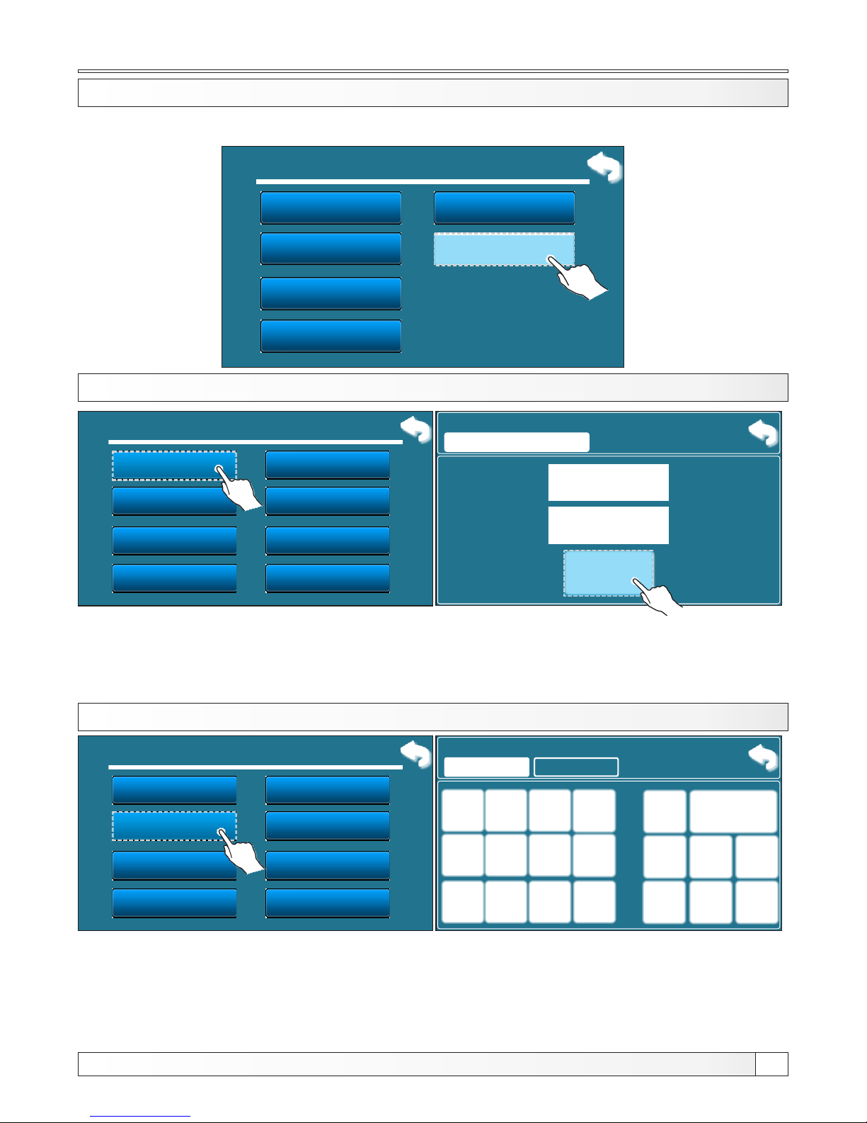
1.6 TEMPERATURES IN HEATING CIRCUIT MOTOR DRIVE
Boiler temp.
Diff. Boiler
DHW temp.
Min buf.tank temp.
1.
2.
3.
4.
5.
Differential of DHW
6.
Heating circuit M.D
1. Temperature
1.6.1 HEATING CIRCUIT MOTOR DRIVE
Possible selection: - factory: ON
-OFF, ON
By using this option ”heating circuit M.D“ can be turned off/on.
1.6.1. Heating circuit M.D
ON
factory:
On
OFF
ON
Heating circuit M.D
Heating curve
Day room temp.
Correction coeff.
1.6 Heating circuit M.D
1.
2.
3.
4.
Transition Time
Table 1
5.
6.
7.
8.
Night room temp.
Day/Night Temp.
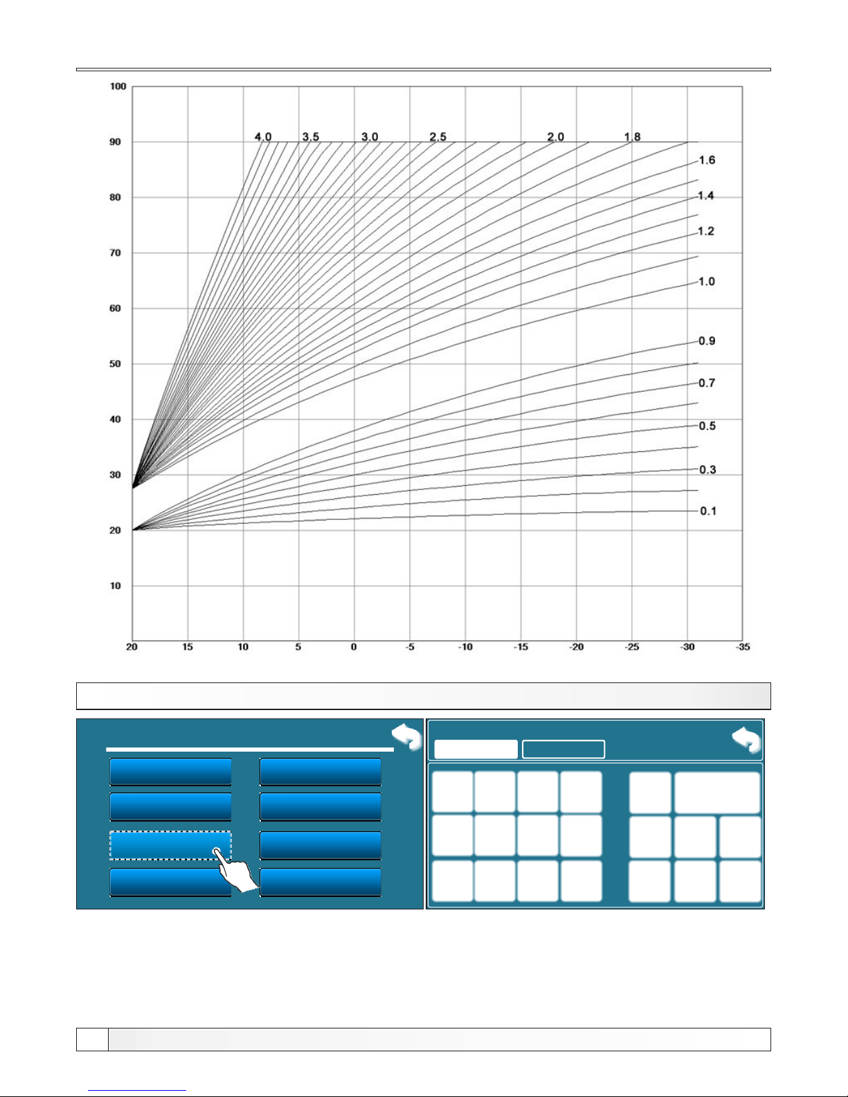
1.6.2 HEATING CURVE
Heating circuit M.D
Heating curve
Day room temp.
Correction coeff.
1.6 Heating circuit M.D
1.
2.
3.
4.
Transition Time
Table 1
5.
6.
7.
8.
Night room temp.
Day/Night Temp.
1.6.2 Heating curve
1.0
1.0
Possible selection - Factory: 1,0
- Minimum: 0,1
- Maximum: 4,0
This parameter determine the coefficient of the heating curve. The regulation calculate required
flow temperature according to the heating curve and outside temperature to achieve the desired
room tempearature.
Technical instructions REGULATION BioTec-L
17
This option is only available when configuration contains motor drive.
Page 18
Temperatures
Outside temperature
Flow temperature
Coefficient
Coefficient
1.6.3 CORRECTION COEFFICIENT
Heating circuit M.D
Heating curve
Day room temp.
Correction coeff.
1.6 Heating circuit M.D
1.
2.
3.
4.
Transition Time
Table 1
5.
6.
7.
8.
Night room temp.
Day/Night Temp.
1.6.3 Correction coeff.
1.0
1.0
Possible selection: - Factory: 1.0
- Minimum: 0,1
- Maximum: 5,0
This parameter determines coefficient of room corrector influence. If is moved 1 step on the room
corrector scale, how many degrees will be changed in regulation.
Technical instructions REGULATION BioTec-L
18
Page 19
Temperatures
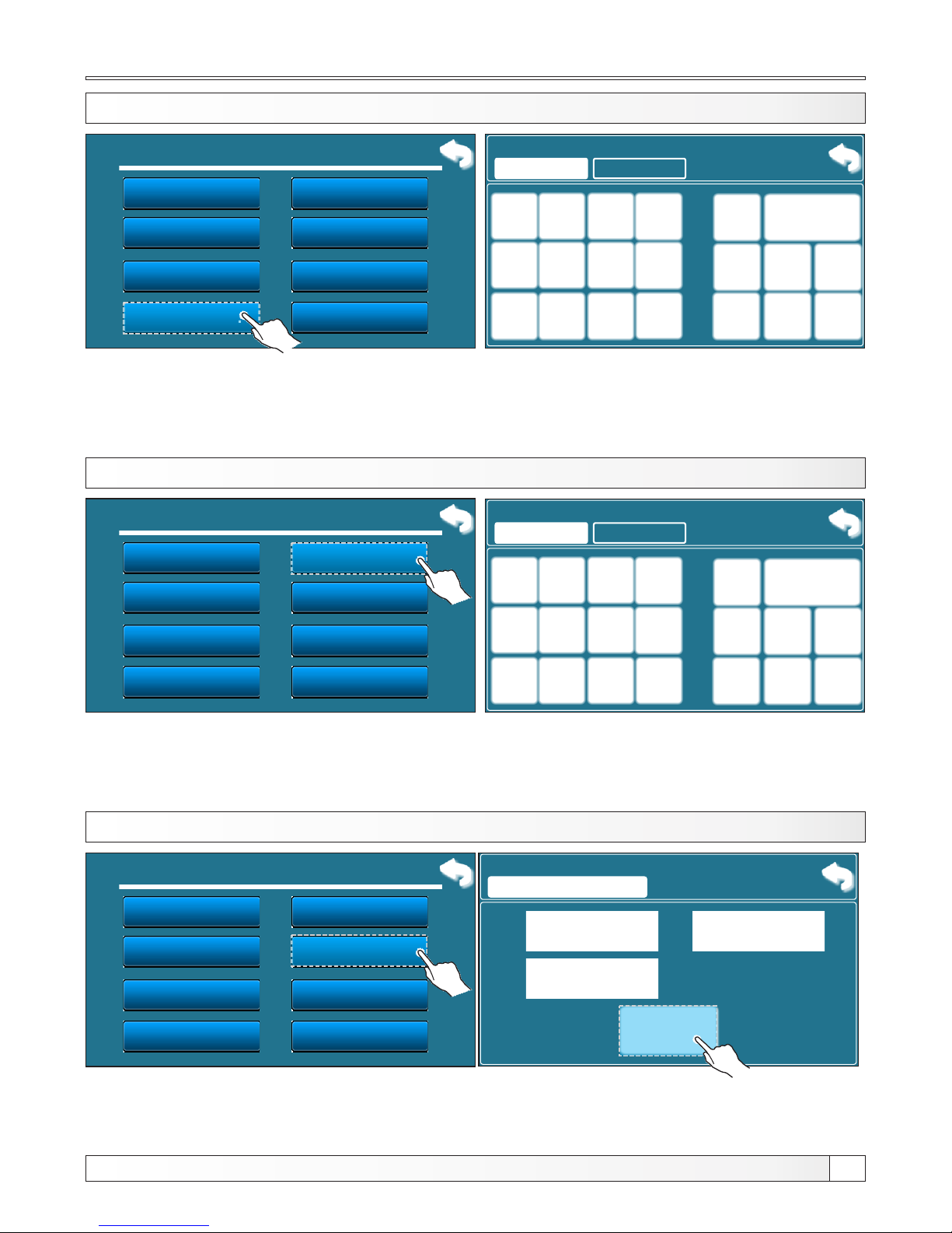
1.6.4 VALUE OF DAY ROOM TEMPERATURE
Heating circuit M.D
Heating curve
Day room temp.
Correction coeff.
1.6 Heating circuit M.D
1.
2.
3.
4.
Transition Time
Table 1
5.
6.
7.
8.
Night room temp.
Day/Night Temp.
Possible selection: - factory: 20,0°C
- Minimum: 5°C
- Maximum: 30,0°C
This parameter determines the value of day room temperature.
1.6.4 Day room temp.
20.0
20.0
°C
1.6.5 VALUE OF NIGHT ROOM TEMPERATURE
Heating circuit M.D
Heating curve
Day room temp.
Correction coeff.
1.6 Heating circuit M.D
1.
2.
3.
4.
Transition Time
Table 1
5.
6.
7.
8.
Night room temp.
Day/Night Temp.
Possible selection: - factory: 20,0°C
- Minimum: 5°C
- Maximum: 30,0°C
This parameter determines the value of night room temperature.
1.6.5 Night room temp.
20.0
20.0
°C
1.6.6 DAY/NIGHT TEMPERATURE CHOICE
Heating circuit M.D
Heating curve
Day room temp.
Correction coeff.
1.6 Heating circuit M.D
1.
2.
3.
4.
Transition Time
Table 1
5.
6.
7.
8.
Night room temp.
Day/Night Temp.
Possible selection: - factory: Day temperature
Day temperature, Night temperature, Table
This option enables you to choose type of desired temperature (day, night or table.) In next page you
can see how to fill a table.
1.6.6 Day/Night Temp.
Day Temp.
Factory:
Day Temp.
Day Temp.
Night Temp.
Table
Technical instructions REGULATION BioTec-L
19
Page 20
Temperatures
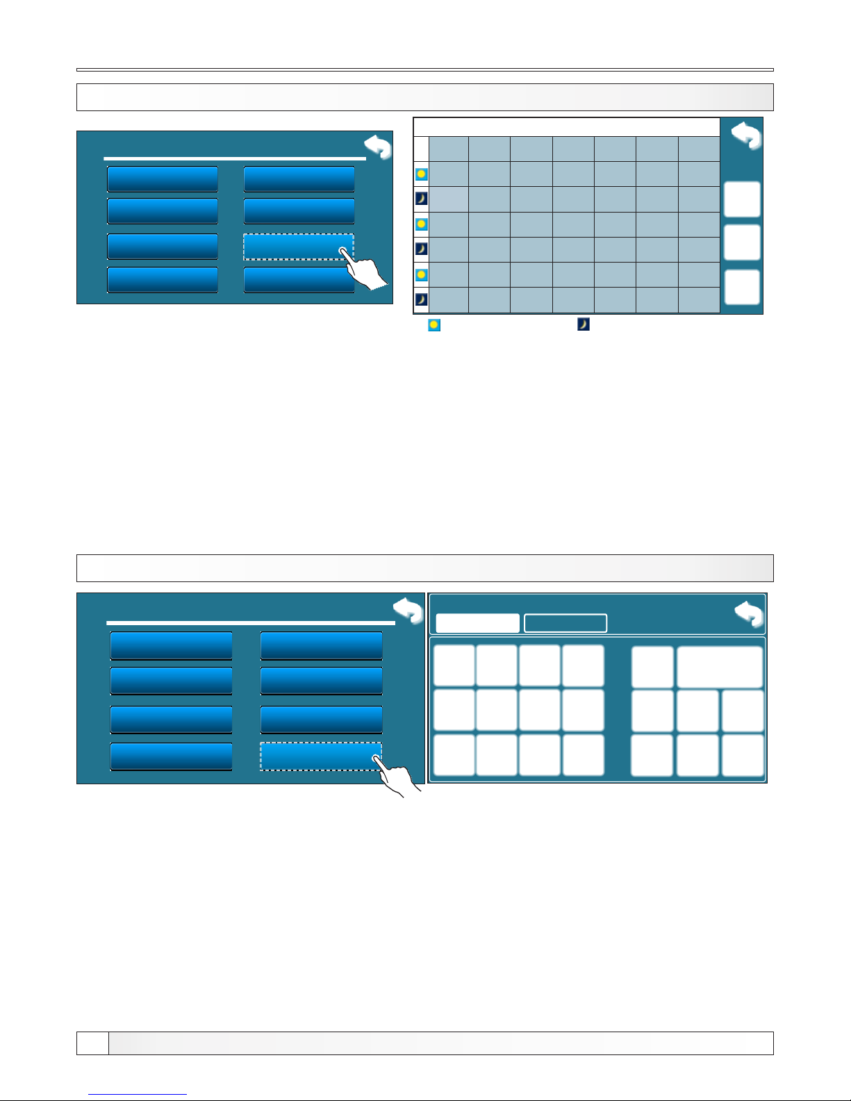
1.6.7 DAY/NIGHT TEMPERATURE TABLE
1. circuit - Table 1
MON
TUE
WED
THU
FRI SAT
SUN
06:00
22:00
06:00
22:00
06:00
22:00
06:00
22:00
06:00
22:00
05:00
10:00
06:00
22:00
14:00
23:00
Day temperature
Night temperature
Each cell marks the beginning of some type (day/night) of selected room temperature.
According to this table every day from monday at 06:00 am is activated day room temperature,
until 22:00 pm when is activated night room temperature until tuesday, when at 06:00 am
is again activated day room temperature.
On saturday, the day temperature is activated at 05:00 am and works until 10:00 am when is
switched to night temperature. At 14:00 pm is again activated day room temperature up to 23:00 pm
when is again switched to night temperature.
When passed one cycle (week) circle starts again from the beginning. The values of a day/night
room temperature can be selected as is described in previous pages.
1.6.8 TRANSITION TIME (is used only when the configuration doesn’t contain room corrector)
Possible selection: - factory: 3600sec
- Minimum: 0 sec
- Maximum: 18000 sec
This parameter is used only when configuration doesn’t contain room corrector, because
regulation doesn’t have information of room temperature.
This parameter is time which is presumed that the system will achieve a given room temperature
in a transition from day to night mode, and vice versa. So, this is time in which will
”flow temperature“ be optimally adjusted to achieve quick transition.
1.6.8 Transition Time.
3600
3600
sec
Heating circuit M.D
Heating curve
Day room temp.
Correction coeff.
1.6 Heating circuit M.D
1.
2.
3.
4.
Transition Time
Table 1
5.
6.
7.
8.
Night room temp.
Day/Night Temp.
Heating circuit M.D
Heating curve
Day room temp.
Correction coeff.
1.6 Heating circuit M.D
1.
2.
3.
4.
Transition Time
Table 1
5.
6.
7.
8.
Night room temp.
Day/Night Temp.
Technical instructions REGULATION BioTec-L
20
Page 21
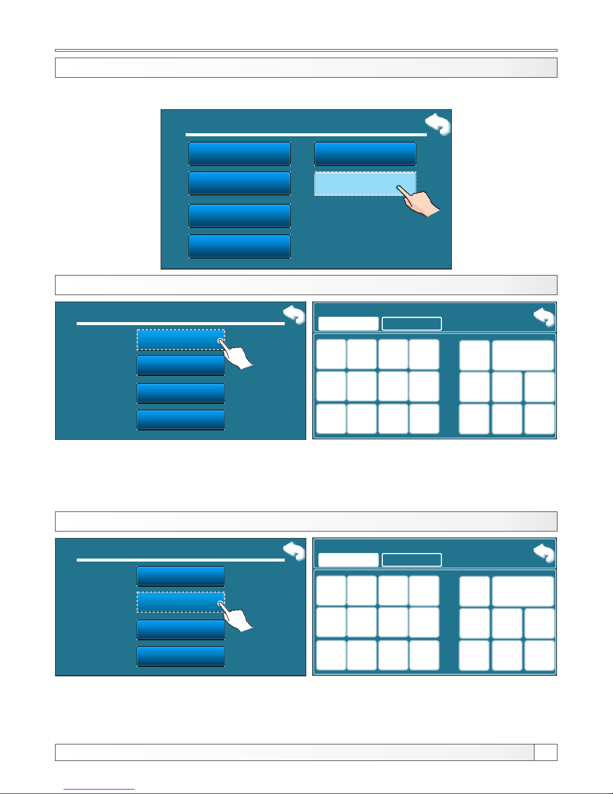
Temperatures
Technical instructions REGULATION BioTec-L
21
1.7 CORRECTOR
Boiler temp.
Diff. Boiler
DHW temp.
Min buf.tank temp.
1.
2.
3.
4.
5.
Differential of DHW
1. Temperature
6.
Corrector
1.7.1 VALUE OF DAY ROOM TEMPERATURE
1.7 Corrector
Day room temp.
Night room temp.
Table 1
Day/Night Temp.
1.
2.
3.
4.
Possible selection: - factory: 20,0°C
- Minimum: 5°C
- Maximum: 30,0°C
This parameter determines the value of day room temperature.
1.7.1 Day room temp.
20.0
20.0
°C
1.7.2 VALUE OF NIGHT ROOM TEMPERATURE
1.7 Corrector
Day room temp.
Night room temp.
Table 1
Day/Night Temp.
1.
2.
3.
4.
Possible selection: - factory: 20,0°C
- Minimum: 5°C
- Maximum: 30,0°C
This parameter determines the value of night room temperature.
1.7.2 Night room temp.
20.0
20.0
°C
This option is only available when the selected components are from configuration 7 (selected
corrector, floor or radiator heating, motor drive is not selected.
Page 22
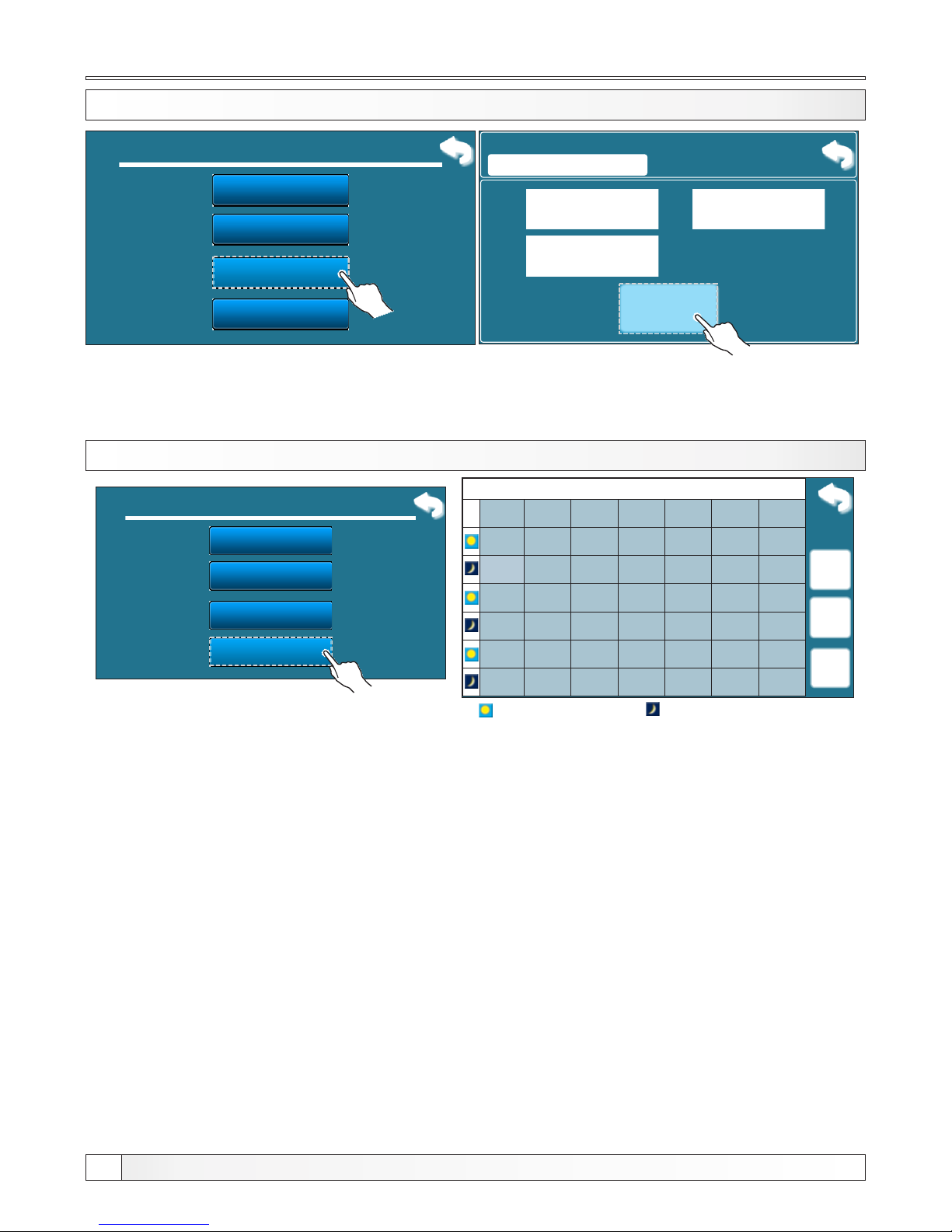
Temperatures
Technical instructions REGULATION BioTec-L
22
1.7.3 DAY/NIGHT TEMPERATURE CHOICE
1.7 Corrector
Day room temp.
Night room temp.
Table 1
Day/Night Temp.
1.
2.
3.
4.
Possible selection: - factory: Day temperature
Day temperature, Night temperature, Table
This option enables you to choose type of desired temperature (day, night or table.)
1.7.3 Day/Night Temp.
Day Temp.
Factory:
Day Temp.
Day Temp.
Night Temp.
Table
1.7.4 DAY/NIGHT TEMPERATURE TABLE
1. circuit - Table 1
MON
TUE
WED
THU
FRI SAT
SUN
06:00
22:00
06:00
22:00
06:00
22:00
06:00
22:00
06:00
22:00
05:00
10:00
06:00
22:00
14:00
23:00
Day temperature
Night temperature
Each cell marks the beginning of some type (day/night) of selected room temperature.
According to this table every day from monday at 06:00 am is activated day room temperature,
until 22:00 pm when is activated night room temperature until tuesday, when at 06:00 am
is again activated day room temperature.
On saturday, the day temperature is activated at 05:00 am and works until 10:00 am when is
switched to night temperature. At 14:00 pm is again activated day room temperature up to 23:00 pm
when is again switched to night temperature.
When passed one cycle (week) circle starts again from the beginning. The values of a day/night
room temperature can be selected as is described in previous pages.
1.7 Corrector
Day room temp.
Night room temp.
Table 1
Day/Night Temp.
1.
2.
3.
4.
Page 23
History
Technical instructions REGULATION BioTec-L
23
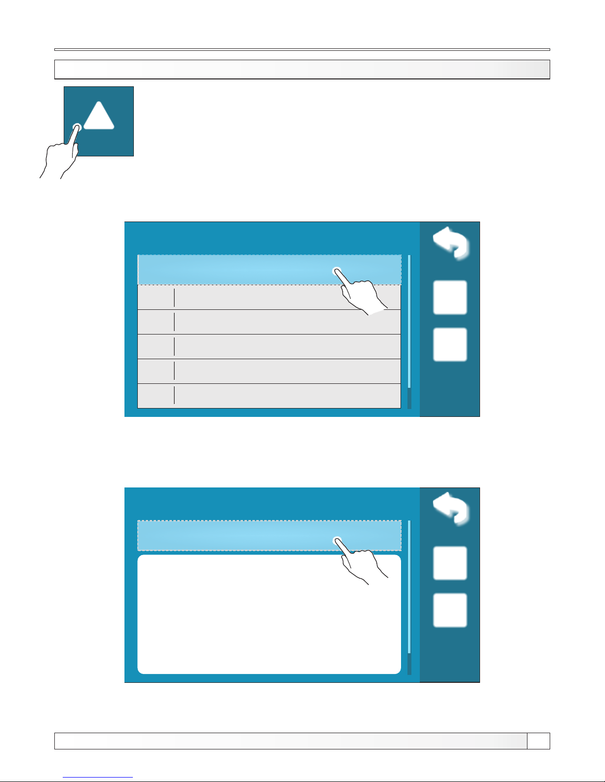
2. HISTORY
History
By pressing this option on the main screen you will see Errors/warnings/
informations list used in order to have an insight into the errors/warnings/
informations that have occurred.
2. HISTORY
History
E6
MAIN FLOW
SENSOR ERROR
OFF
16-Feb-2015 13:53:01
02-Jan
07-Jan
15-Jan
26-Jan
29-Jan
E14
W5
I2
E24
E5
LAMBDA PROBE ERROR
INTERVENTION WORK
(Lambda sensor)
IGNITION AUTOMATICLY
PROCEEDED
ROOM CORRECTOR
ERROR
OUTSIDE TEMPERATURE
SENSOR ERROR
History
E6
MAIN FLOW
SENSOR ERROR
OFF
16-Feb-2015 13:53:01
Empty
The first press on the field error/warning/information field is indicated, in addition
to see and date generated errors/warnings/information
1x
The second press on the selected error/warning/information, prints a detailed description
of the error/warnings/information and corrective action errors/warnings/information. If for
some error/warning/information there is no description on current software version, on
the screen will be displayed ”empty“.
2x
Written is:
- time of occurrence errors/ warnings/ informations
- error/warning/information code
- description of the error/warning/information.
Page 24
File
File
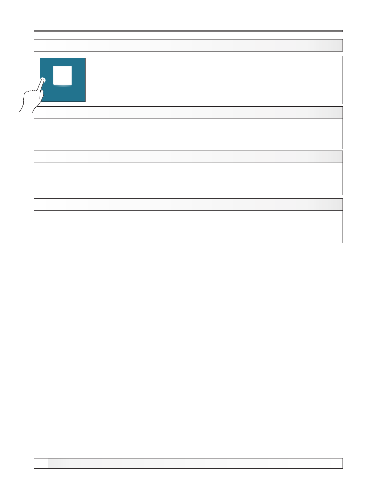
3. FILE
3.1. LOAD FACTORY
3.2. SAVE
3.3. LOAD
3. FILE: By pressing this option on the main screen you will see menu with:
After pressing ''LOAD FACTORY'' you will see a message ''LOAD FACTORY SETTINGS?''.
Pressing button ''OK'' will load the default settings of regulation. Pressing the'' BACK'' will return to
the previous menu.
3.1. LOAD FACTORY
3.2. SAVE
After pressing ''LOAD’' you will see ''LOAD SAVED SETTINGS?''. Pressing button ''OK'' saved
settings (saved in option SAVE) will be loaded. Pressing the ''BACK'' will return to the previous
menu.
3.3. LOAD
After pressing ''SAVE'' you will see a 3 slots to save data (Memory 1, 2, 3). Presing to one of this three
buttons you will se message ''SAVE CURRENT SETTINGS?''. Pressing button ''OK'' the current
setting of regulation will be saved in memory. Pressing the ''BACK'' will return to the previous menu.
Technical instructions REGULATION BioTec-L
24
Page 25
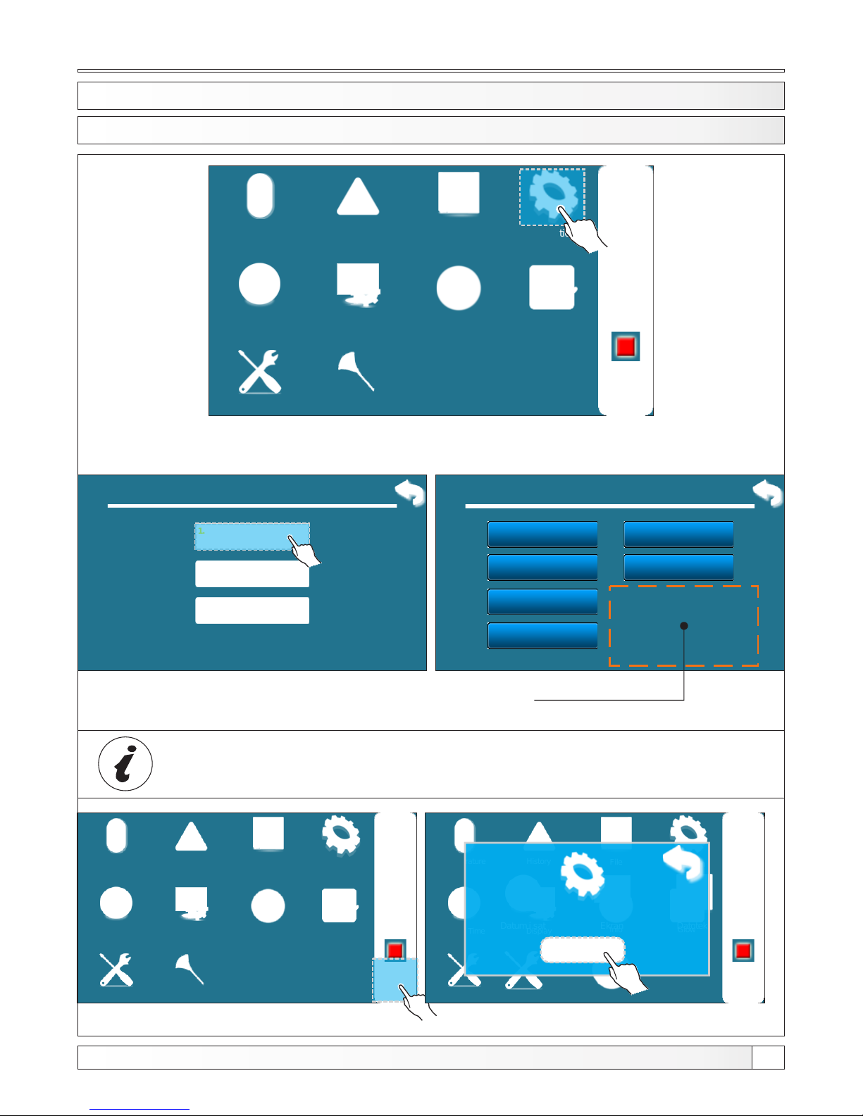
Operation
4. OPERATION
Operation
Installation
Temperature
History
Date & Time Display
Info
File
02:11
OFF
Glow
To enter in Operation menu press ”Operation” button.
4.1. Manual test
Secondary open
5.
Secondary close
4.
P1
6.
Primary open
3.
Primary close
2.
Fan
1.
4. Operation
Manual test
1.
Chimney sweeper
2.
Parts in this section depend
about heating configuration
Cleaning
Forced shutdown
3.
4.1 MANUAL TEST
Technical instructions REGULATION BioTec-L
25
Operation
Installation
Temperature
History
Date & Time Display
Info
File
02:11
OFF
Glow
Cleaning
Operation
Installation
Temperature
History
Date & Time Display
Info
File
02:11
OFF
Glow
Instalacija
Datum i sat Ekran
Informacije
Datoteka
STOP?
To be able to use manual test, you must first turn ”OFF“ the
boiler in the usual way by pressing button and then STOP.
Page 26
Info
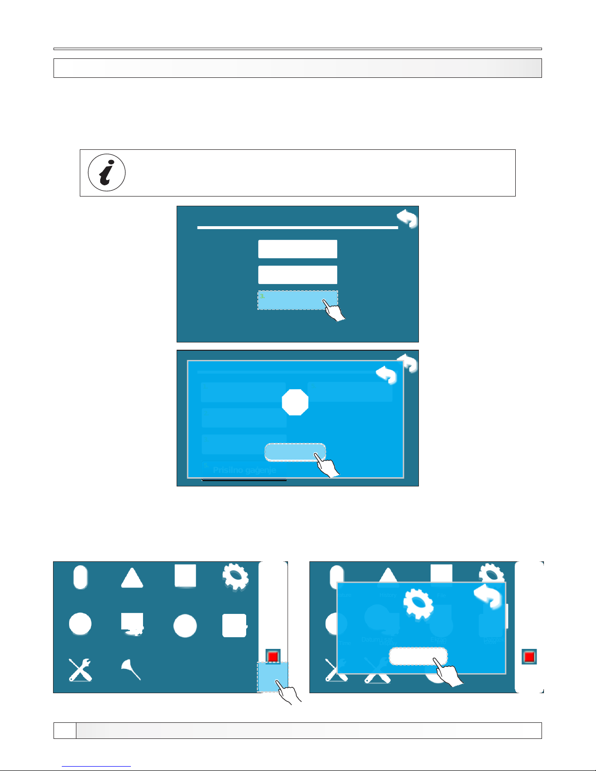
4.3 FORCED SHUTDOWN
This option is used to forced stop all processes.
First must be pressed the ON/OFF button to put the boiler in shutdown procedure and then ''forced
shutdown'' button. All processes are stopped.
IMPORTANT! To be able to stop all processes, you must first turn off the
boiler in the usual way by pressing and then STOP.
Operation
Installation
Temperature
History
Date & Time Display
Info
File
02:11
OFF
Glow
Cleaning
Operation
Installation
Temperature
History
Date & Time Display
Info
File
02:11
OFF
Glow
Instalacija
Datum i sat Ekran
Informacije
Datoteka
STOP?
5. Način rada
PTV / Grijanje
Dimnjačar
1.
Ručni test
2.
3.
Čistač dim. prolaza
5.
Prisilno gašenje
5.
Stop all processes?
4. Operation
Manual test
1.
Chimney sweeper
2.
Forced shutdown
3.
Option ”FORCED SHUTDOWN“ is not usual procedure for
turning OFF the boiler
Technical instructions REGULATION BioTec-L
26
Page 27
Date and time, display
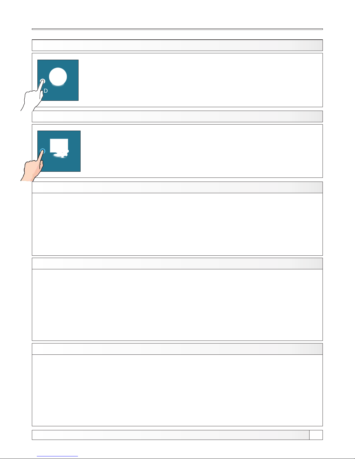
5. DATE AND TIME
By pressing this option on the main screen you can set the date and time. This
option is used to set the date and time. It is necessary for starting times, and the
recording of errors/warnings/informations (for the occurrence of errors /
warnings, remembers the date and time of occurrence). After setting the date
and time it is necessary to press the ''CONFIRM'' for saving date and time.
Date & time
6. DISPLAY
Display
6.1. Screensaver
6.2. Language selection
6.3. Init. message time
6. Display: By pressing this option on the main screen you will see menu with:
Default: 600 seconds
Minimum: 10 seconds
Maksimum: 3600 seconds
If at some time nothing was pressed on the screen, the screensaver will turn on, to prevent damage
on the screen. Once you touch the screen, the screensaver will turn of.
6.1. SCREENSAVER
Possible selection:
OFF
ON (default)
This option enables or disables screen with the choice of language regulation when you turn-on
main switch. If is marked ''OFF'', after turning-on the main switch, it will be set on before selected
language and after some time, display will show the work display of the boiler (duration of this screen
can be adjusted in Section x.x.).
Default: 5 seconds
Minimum: 0 seconds
Maksimum: 20 seconds
This option is used to set the desired duration of the initial message after turning on the main switch.
This option is only available if the option'' LANGUAGE SELECTION'' (point 7.2.) Is set to'OFF''.
6.2. LANGUAGE SELECTION
6.3. INITIAL MESSAGE TIME
Possible selection
Possible selection:
Technical instructions REGULATION BioTec-L
27
Page 28
Info
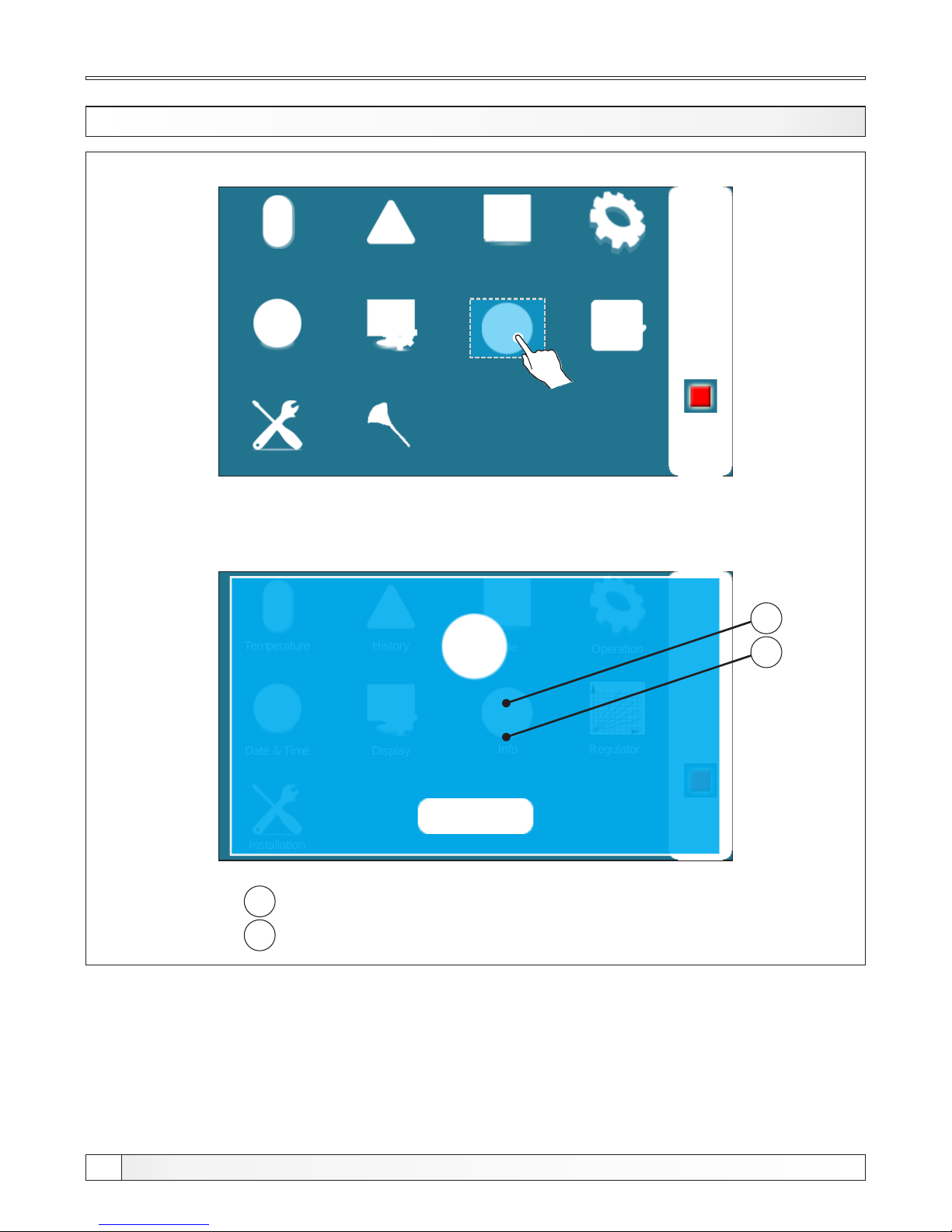
7. INFO
Operation
Installation
Temperature
History
Date & Time Display
Info
File
02:11
OFF
Glow
To view informations about boiler and software press Info button.
Operation
Installation
Temperature
History
Date & Time Display
Info
File
02:11
OFF
Regulator
v2.35L
25kW
SID: 72CDCE37
1
2
1
2
- Software version
- Boiler power
Cleaning
Technical instructions REGULATION BioTec-L
28
Page 29
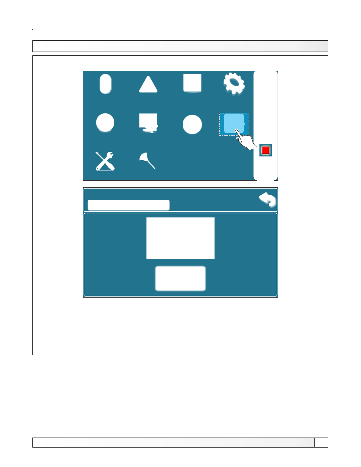
Glow
8. GLOW
Operation
Installation
Temperature
History
Date & Time Display
Info
File
02:11
OFF
Glow
7. Glow
ON
Default:
OFF
OFF
In menu "Glow” option for glow maintenance can be turned on or of.
ENABLED OPTION GLOW: when, on fuel load storage, remain only glow, boiler
can maintain remain glow for max 12h, depend about heating requirement
ON
Cleaning
Technical instructions REGULATION BioTec-L
29
Page 30
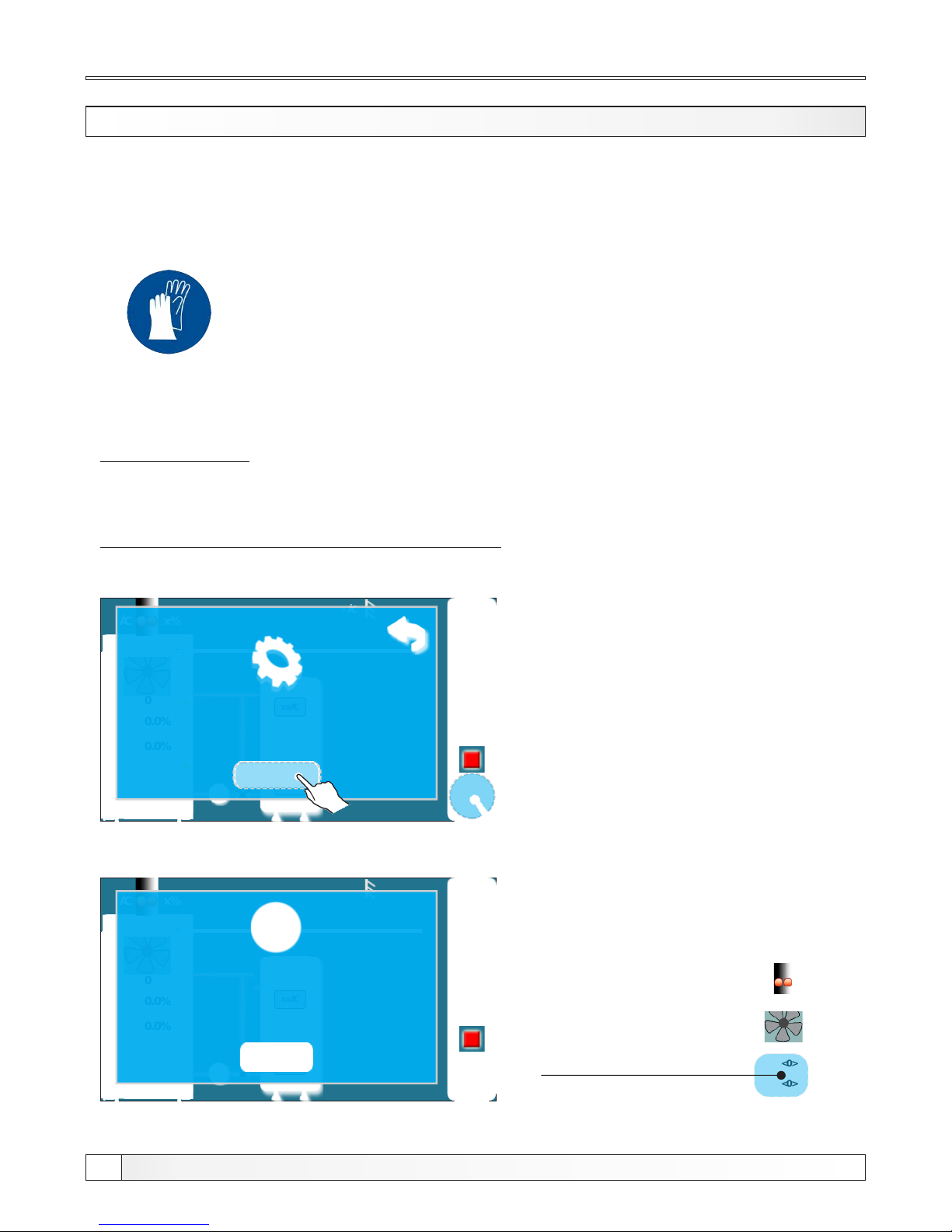
Ignition
IGNITION
Boiler must not be used in flammable and explosive environment. It must not be used by children or
disabled persons (either physically or mentally), as well as by person without knowledge or
experience, unless they are under control or trained by s person responsible for their safety.
Children must be supervised in the vicinity of the product. Protective gloves must be used!
Protective gloves must be used!
IGNITION PHASE:
- Open upper and middle boiler doors (see pages 4 i 5 in “Technical instructions for installation of
hot water boiler BioTec-L”)
Follow these steps for succesfull igniton phase:
05:08
OFF
0
0.0%
0.0%
- °C
x%xx°C
xx°C
xx°C
xx°C
2.
3.
5.
START?
- press button for boiler start
- on display will be displayed window for
boiler start
- press ”OK” button
05:08
OFF
0
0.0%
0.0%
- °C
x%xx°C
xx°C
xx°C
xx°C
Primary and secondary wings
seeking initial position. Please
wait and try again.
- if this message is shown on display than
wait for primary and secondary air actuators
- primary and secondary air is ready for work
when indicator stop blinking
0
<0>
<0>
x%xx°C
xx°C
Primary and secondary
air indicators.
Technical instructions REGULATION BioTec-L
30
Page 31
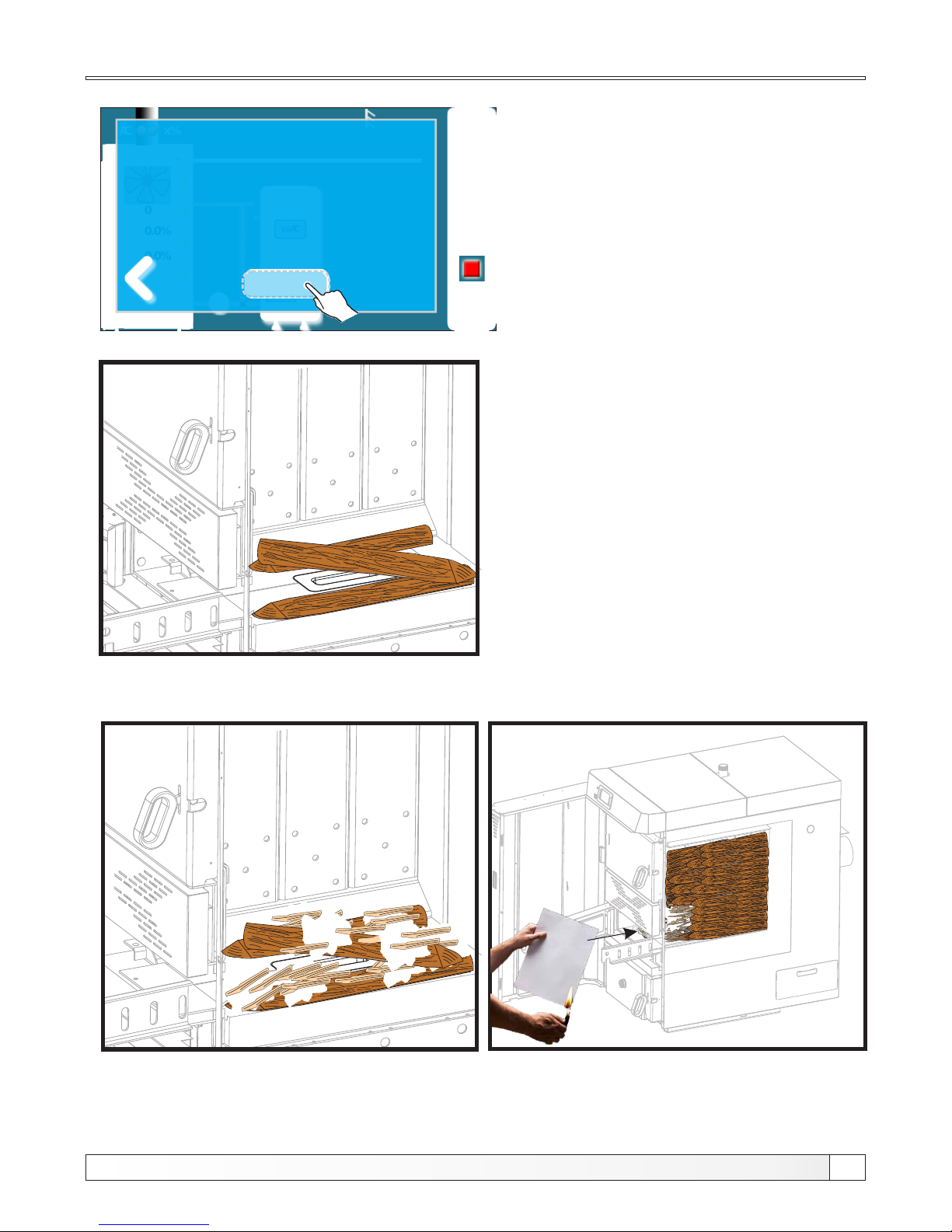
Ignition
05:08
OFF
0
0.0%
0.0%
- °C
x%xx°C
xx°C
xx°C
xx°C
1.
2.
3.
5.
IGNITION (1/3)
- Fill the boiler with wood!
- Close the upper and lower door!
- Leave middle door opened!
- Start the fire!
- on display is displayed message
"IGNITION 1/3"
- cover the refractory stone with one row
of wood logs (be careful to not plug hole
on refractory stone (detail A)
- cover the wood logs with fine chopped wood
(use enough fine chopped wood to cover
wood logs below)
- height of fine chopped wood layer must
conform a approx. height of first row of wood
logs
- cover the fine chopped wood with crumped
paper (use enough crumpled paper to cover
fine chopped wood) (detail B)
- place the wood logs on crumpled paper
- fill the fuel loading chamber with wood logs
(detail C)
- close upper and lower doors
- leave middle door opened
- ignite the fire throuh middle boiler door
(detail C)
- press enter button” “
Technical instructions REGULATION BioTec-L
31
Detail A
Detail B Detail C
Page 32
05:08
OFF
0
0.0%
0.0%
- °C
x%xx°C
xx°C
xx°C
xx°C
PTV / Grijanje
Dimnjačar
1.
Ručni test
2.
3.
Čistač dim. prolaza
5.
Prisilno gašenje
5.
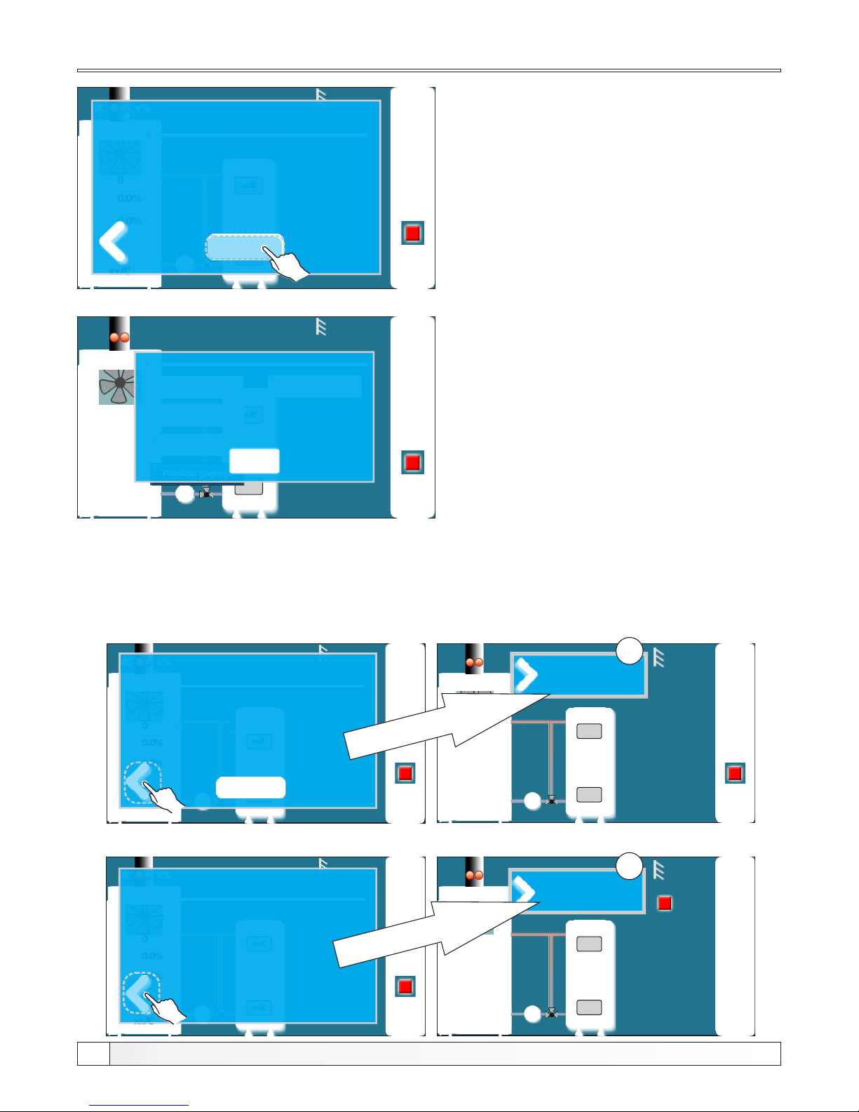
IGNITION (3/3)
When you close the middle door,
press the button
AUTOMATIC
CONTINUE:
04:41
- on display is displayed message
"IGNITION 3/3"
- close middle boiler door
- press ”enter” button
- if you don’t press ”enter” button boiler will
be automatic continue when counter count
to zero (automatic continue)
05:08
OFF
0
0.0%
0.0%
xx°C
x%xx°C
xx°C
xx°C
xx°C
IGNITION (2/3)
- Wait until the flue gas
temperature rises:
Additional:
05:08
OFF
0
0.0%
0.0%
- °C
x%xx°C
xx°C
xx°C
xx°C
1.
2.
3.
5.
IGNITION (1/3)
- Fill the boiler with wood!
- Close the upper and lower door!
- Leave middle door opened!
- Start the fire!
05:08
OFF
0
0.0%
0.0%
xx°C
x%xx°C
xx°C
xx°C
xx°C
IGNITION (1/3)
- Fill the boiler with wood!
- Close the upper and
lower door!
05:08
OFF
0
0.0%
0.0%
- °C
x%xx°C
xx°C
xx°C
xx°C
1.
IGNITION (2/3)
- Leave middle door opened!
Wait until the flue gas
temperature rises:
22°C/50°C
1
1
During ignition phase is possible to see main display. It is neccessary to press button.
Because ignition phase is on proces, display will be displayed current ignition step to (1). By
pressing button we return to full preview of ignition phase.
Technical instructions REGULATION BioTec-L
32
05:08
OFF
0
0.0%
0.0%
- °C
x%xx°C
xx°C
xx°C
xx°C
1.
IGNITION (2/3)
- Leave middle door opened!
Wait until the flue gas
temperature rises:
22°C/50°C
- on display is displayed message
"IGNITION 2/3"
- on this step is neccessary to wait until flue
gas temperature raise 50°C
- middle boiler door must be opened all time
- when is flue gas temperature higher than
50°C press ”enter“ button
xx°C
Page 33
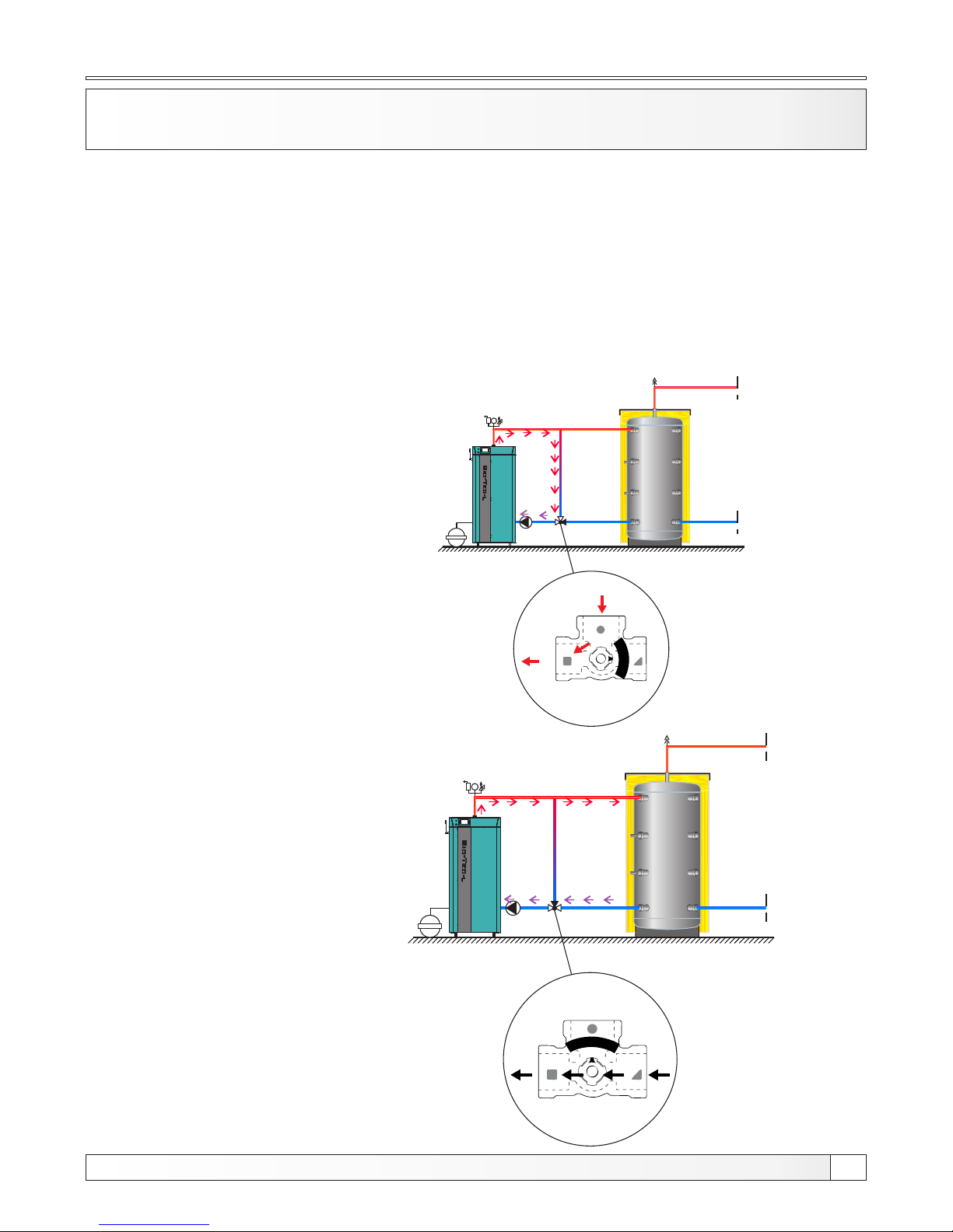
3-WAY MIXING VALVE WITH EL. ACTUATOR
(RETURN FLOW PROTECTION) (PROTECTION VALVE)
bar
bar
Case 1. Valve is 100% closed
Case 2. Valve is 100% open
3-way mixing valve must be installed according to the next steps:
- when is presed button ”Valve closing” in manual test valve must closed entry from
accumulation tank (see Case 1)
- when is pressed button ”Valve opening” in manual test valve must open entry from
accumulation tank and close bypass (see Case 2)
- depend on el. actuator type is neccessary to input valve opening time on installation menu
In below of this technical instruction see how to make manual test of protection valve
Protection valve
Technical instructions REGULATION BioTec-L
33
Page 34
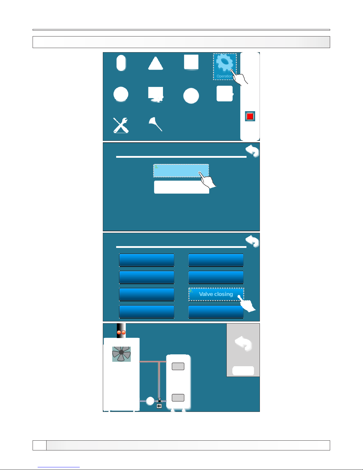
MANUAL TEST (VALVE CLOSING)
Operation
Installation
Temperature
History
Date & Time Display
Info
File
02:11
OFF
Glow
4. Operation
Manual test
1.
Chimney sweeper
2.
4.1. Operation
Fan
Primary close
Primary open
Secondary close
Secondary open
P1
Valve closing
Valve opening
1.
2.
3.
4.
5.
6.
7.
8.
0
0.0%
0.0%
x%xx°C
xx°C
xx°C
xx°C
xx °C
Manual test
Valve closing
After test, valve must be completely closed (like as shown in Case 1).
Protection valve
Cleaning
Technical instructions REGULATION BioTec-L
34
Page 35
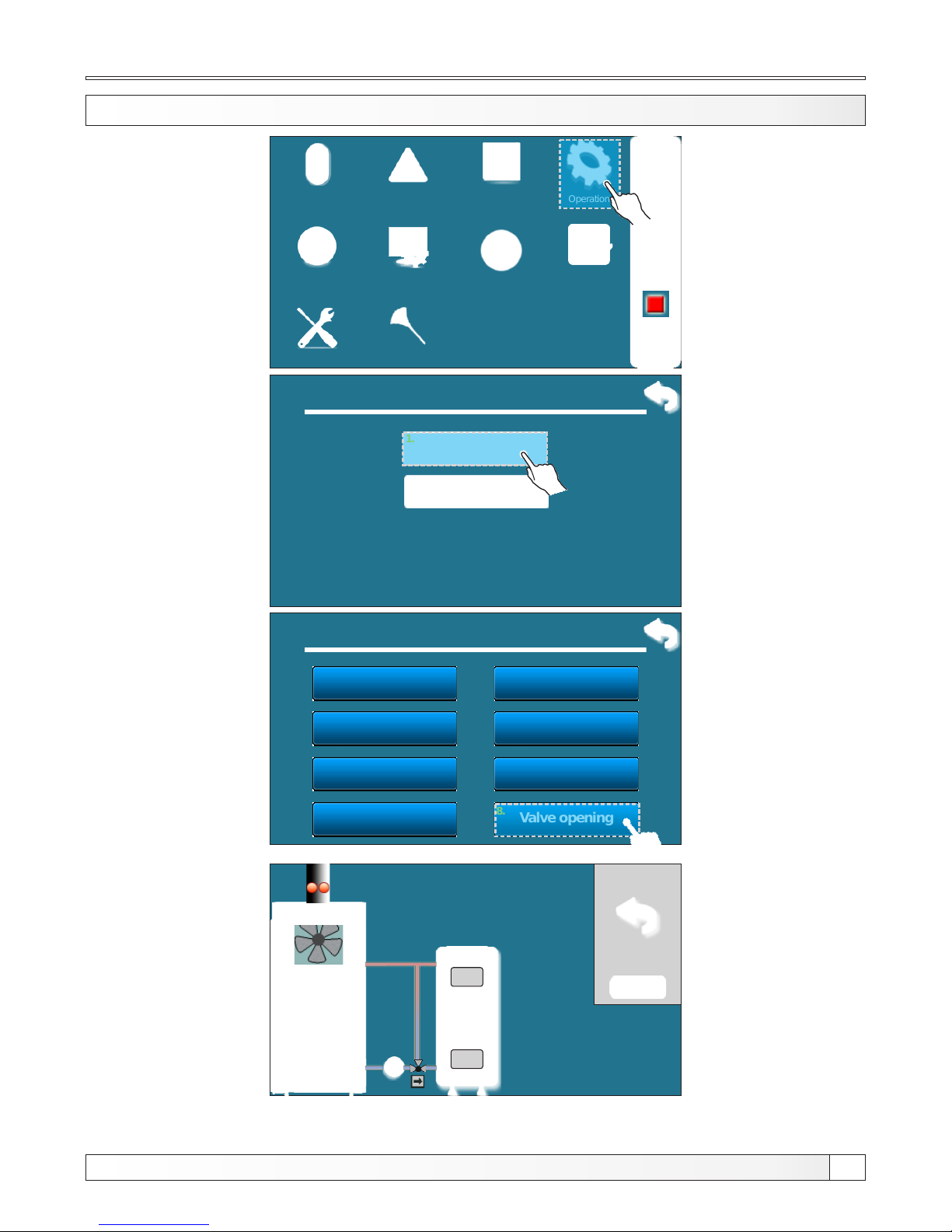
MANUAL TEST (VALVE OPENING)
Operation
Installation
Temperature
History
Date & Time Display
Info
File
02:11
OFF
Glow
4. Operation
Manual test
1.
Chimney sweeper
2.
4.1. Operation
Fan
Primary close
Primary open
Secondary close
Secondary open
P1
Valve closing
Valve opening
1.
2.
3.
4.
5.
6.
7.
8.
0
0.0%
0.0%
x%xx°C
xx°C
xx°C
xx°C
xx °C
Manual test
Valve opening
After test, valve must be completely opened (like as shown in Case 2).
Protection valve
Cleaning
Technical instructions REGULATION BioTec-L
35
Page 36
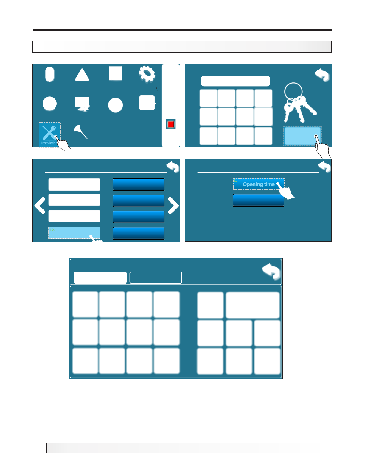
OPENING TIME (authorized persons only)
Operation
Installation
Temperature
History
Date & Time Display
Info
File
02:11
OFF
Glow
Enter PIN
* * * *
9. Installation
Display
File
Other
Heating circuit
13.
14.
15.
16.
Temp. firebox
9.
Glow
10.
Flue gas temp.
11.
Protection valve
12.
9.12 Protection valve
Opening time
Timebase
1.
2.
9.12.1 Opening time
270
270
sec
In this step is neccessary to input el. actuator opening time (labeled on el. actuator by
manufacturer. This step is crucial for proper operation of el. actuator.
Protection valve
Cleaning
Technical instructions REGULATION BioTec-L
36
Page 37
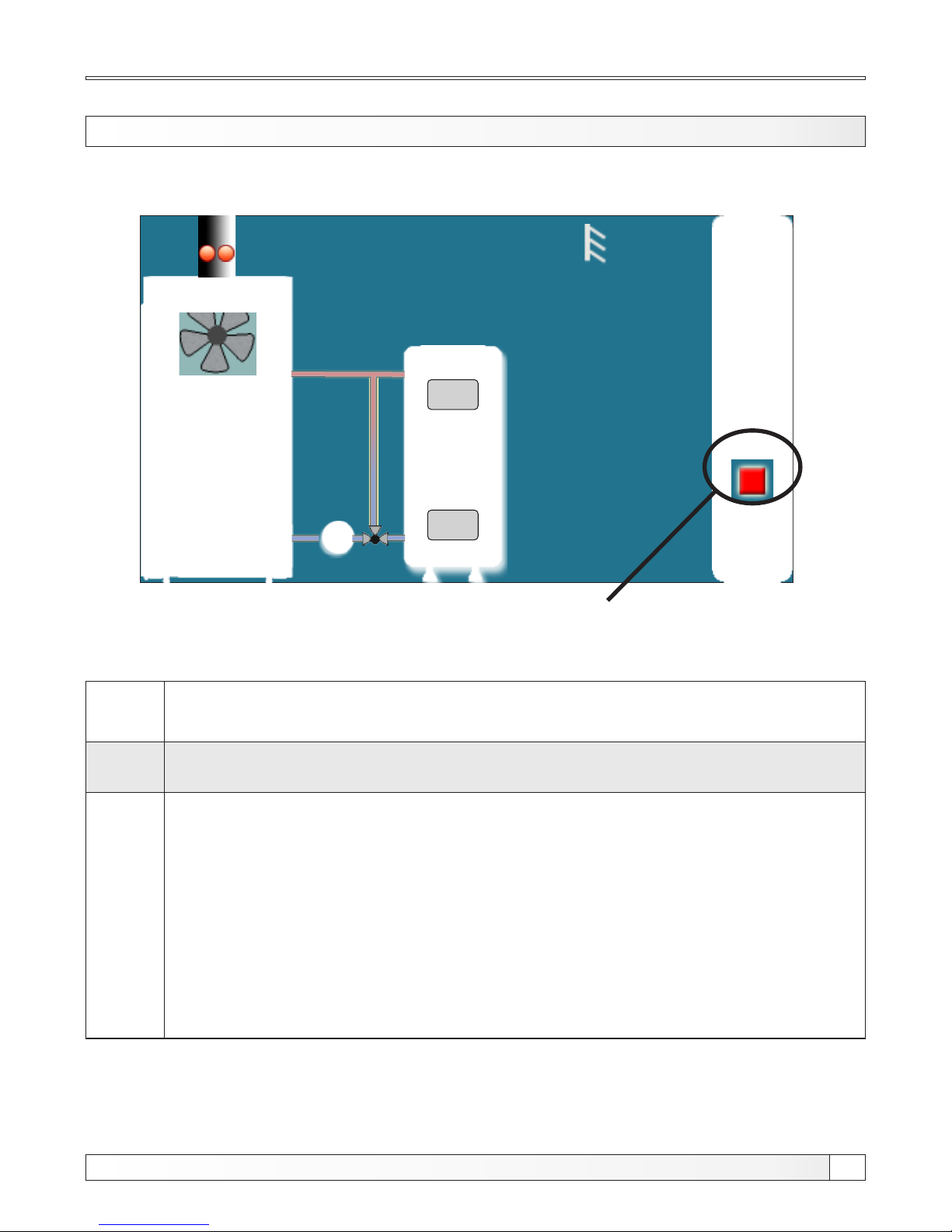
Operation phases
OPERATION PHASES (SHOWN ON THE SCREEN)
05:08
OFF
0
0.0%
0.0%
xx°C
x%xx°C
xx°C
xx°C
xx°C
xx °C
Operation phases
OFF
The boiler is switched off (standby boiler until the next start).
Operation
phase
Description
S0
- The message on the screen: "IGNITION 1/3".
- Fan works on max. speed
- Primary / secondary is positioning themselves.
- The process continues to the next phase "S1" after the user confirms the
message or automatically if the Tdp (flue gas temperature) is higher
than 50 ° C. If Tdp is higher then 50 ° C at the time of starting the
operation of the boiler phase "S0" does not appear on the screen
(automatically skipped).
Technical instructions REGULATION BioTec-L
37
Page 38

Description
Operation phases
S1
- The message on the screen: "IGNITION 2/3".
- Fan works on max. speed
- Primary / secondary is positioning themselves.
- Waiting for the Tdp> 50°C.
When Tdp> 50°C:
a) The user can confirm the message "IGNITION 2/3" then screen will
show the message "IGNITION 3/3" which user also can confirm which
exceeds the boiler in the next phase "SP1" or "SP2".
b) If the user didn’t confirm the message "IGNITION 2/3" or didn’t
confirm message "IGNITION 3/3" boiler will after 5 minutes
automatically switch to the next phase "SP1" and on the screen remains
message "IGNITION 3/3" with the inscription "automatic continuation".
This message remains on the screen until the confirmation by the user
but has no effect on the operation of the boiler.
Exceptions:
1. If upper boiler door is opened, there is no possibility of manual
confirmation of the message "IGNITION 2/3" either is not possible
to automatically move to the next message "IGNITION 3/3". Closing
the upper boiler door, boiler moves to above described (normal)
procedure phase "S1".
2. If upper boiler door is opened when on the screen is displayed message
"IGNITION 3/3" move to the next stage ("SP1") or "SP2" is only possible
by using the manual message confirmation while automatically is not
possible.
SP1
- Setting the start position primary / secondary is necessary for the next
phase "SP2".
- When the primary / secondary are adjusted boiler goes into a phase
"SP2",
- If the required position of primary / secondary had been set earlier,
this phase "SP1" doesn’t appear on the screen).
Operation
phase
Technical instructions REGULATION BioTec-L
38
Page 39

Operation phases
Description
SP2
- The time of duration this stage "SP2" is factory defined.
- Before the end of this stage regulation based on the measured
parameters of the boiler operation allows the transition to the next
phase "SD4" ("DX") or otherwise records information in history and
extends this state "SP2" for factory defined time period after which
repeats the comparison of the measured and the required
parameters and allow you to move to the next stage "SD4" ("DX")
or if the conditions are not satisfy writes an error and stops the
operation of the boiler.
SD4
- Set the power blades D4
- If the required position primary / secondary had been earlier set this
state "SD4"does not appear on the screen.
Dx
- Stage "DX" is the common name for operation phases of the boiler
on “D4","D3","D2","D1".
- phase “DX” doesn’t appear displayed on the screen but is displayed one
of the operation of the boiler “D4", "D3", "D2", "D1" which depends about
boiler modulation phase.
DOP0
(understage)
- Indicate that the upper boiler door is opened.
DIF1
- Turning off the boiler either due to reaching the set temperature of the
boiler, too low combustion chamber temperature or too high flue gas
temperature (Tdp>300 °C ).
DIF2
- The boiler wait that the temperature in boiler drops to the set temperature
of the boiler reduced by set differential.
DIF3
- Blowout while boiler is waiting that temperature in boiler drops to the set
temperature of the boiler reduced by set differential.
DIF4
- Start boiler-setting primary / secondary, after the boiler temperature
dropped to the set temperature of the boiler reduced by set differential.
Operation
phase
Technical instructions REGULATION BioTec-L
39
Page 40
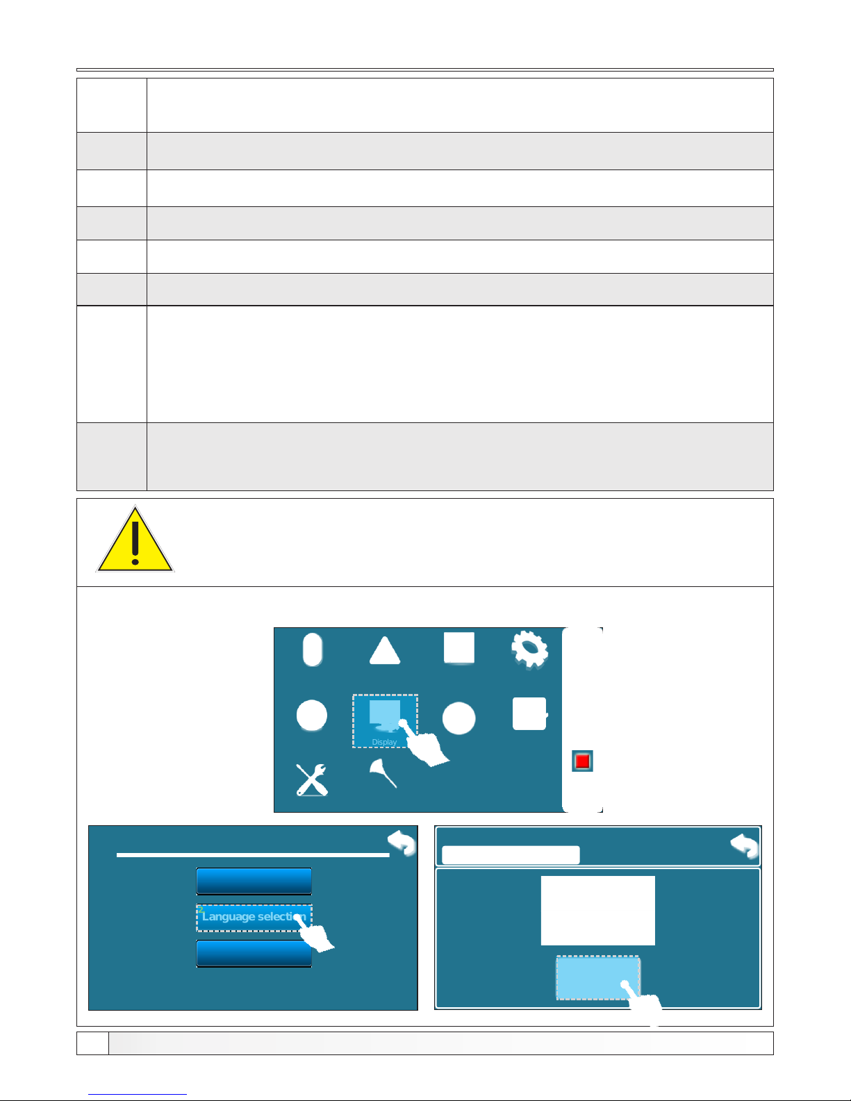
Operation phases
Description
GLW1
- Shutting down the boiler for keeping the glow.
GLW2
- Phase of keeping the glow.
GLW3
- Glow blowout in phase of keeping the glow.
GLW4
- Start a new filling, set the primary / secondary.
OFF1
- Shutting down after which the boiler goes into phase „OFF“.
PF-XXXX
- xxxx: Is any phase described above (for example PF-GLW2)
- Appears after a power off/power in if there was a power failure.
- The prefix "PF" disappears with new start of the boiler or by
using option "forced shut down"
PF-ON
- This stage is printed during zeroing primary / secondary and after
a power switch off / switch on. It indicates that after zeroing
primary / secondary boiler automatically start again.
IMPORTANT!
Automatically resume boiler operation after the disappearance
of electric power (PF phases) is not possible if language
selection option is turned on.
For turning off the ”language selection option“ follow steps below:
Operation
Installation
Temperature
History
Date & Time Display
Info
File
02:11
OFF
Glow
Cleaning
6. Display
Screensaver
Language selection
1.
2.
Init.message time
3..
6.2. Language selection
ON
Factory:
ON
OFF
ON
Operation
phase
Technical instructions REGULATION BioTec-L
40
Page 41
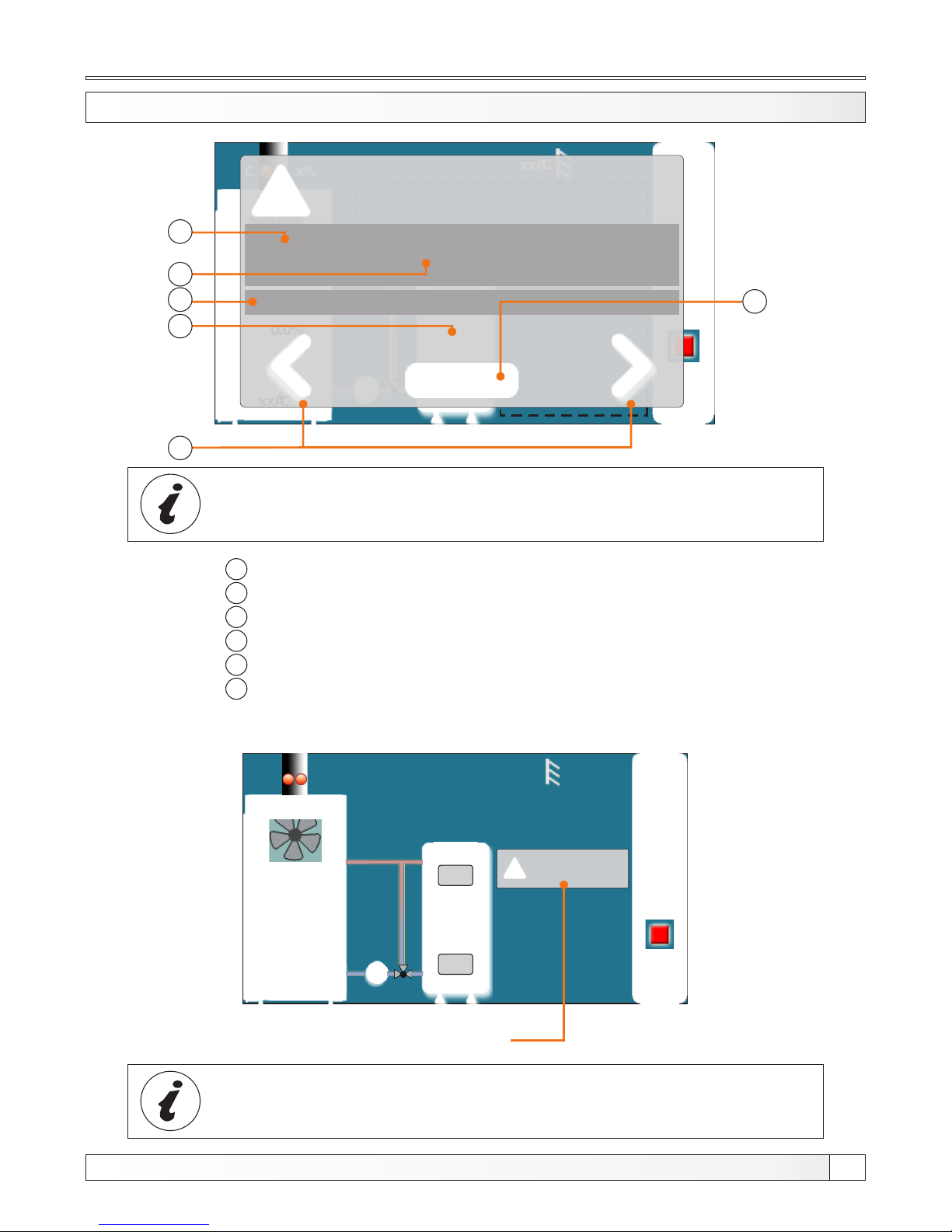
Example of the error/warning that appears on the main screen
1
2
3
4
5
6
Error / Warning / Information code
Error / Warning / Information name
Date and time of error / warning / information occurrence
Number of errors / warnings / informations
„OK” button
Buttons for scrolling through errors / warning / informations
05:08
OFF
0
0.0%
0.0%
xx°C
x%xx°C
xx°C
xx°C
xx°C
xx °C
ERRORS: X
WARNINGS: X
Minimized window on main display
By pressing „OK” button error window will be minimized and showned on main display.
ERROR/WARNING ON THE MAIN SCREEN
All errors/warnings are recorded in history (see point 2.History)
05:08
OFF
0
0.0%
0.0%
xx°C
x%xx°C
xx°C
xx°C
xx°C
xx °C
ERRORS - WARNINGS
x/x
E1
DHW SENSOR
ERROR
Appear: 15.09.2014. 11:30:46
1
2
3
4
6
5
Technical instructions REGULATION BioTec-L
41
When the error/warning still present, error/warning name and code
is painted red, and when error/warning is resolved, text turns green
Page 42
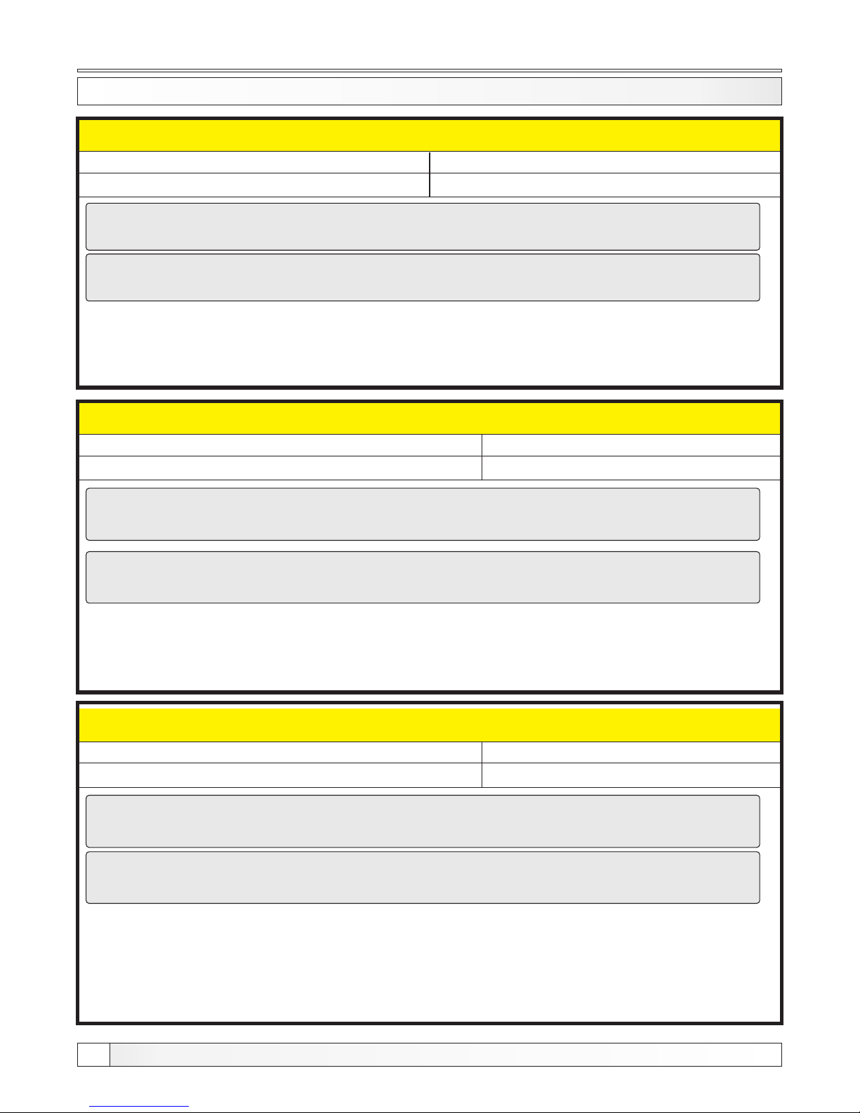
Errors, warnings
Technical instructions REGULATION BioTec-L
42
LIST AND ELIMINATION OF ERRORS / WARNINGS / INFORMATIONS
Error
Boiler status
DHW SENSOR
Intervention mode
Causes
Error in temperature sensor in sanitary water tank.
What to do?
Check sensor position, check damages of sensor and cables, check contacts on connectors.
Press „OK” button to confirm error. Boiler will continue with work but on main screen will be
showned information about error. Instead temperature, on DHW tank will be showned „-°C”.
ERROR E1
Error
Boiler status
BUFFER TANK SENSOR ERROR (UP)
Intervention mode
Causes
Error in buffer tank sensor (up).
What to do?
ERROR E2
Error
Boiler status
Boiler work normally
Causes
What to do?
ERROR E3
Intervention mode: Boiler work to content heating demand but boler has reduced possibilities.
If upper instructions didn’t help call service man.
Check sensor position, check damages of sensor and cables, check contacts on connectors.
Press „OK” button to confirm error. Boiler will continue with work but on main screen will be
showned information about error. Instead temperature, on buffer tank (up) will be shown „-°C”
and the request for AKU-tank temperature will not working.
Intervention mode: Boiler work to content heating demand but boler has reduced possibilities.
If upper instructions didn’t help call service man.
BUFFER TANK SENSOR ERROR (DOWN)
Error in buffer tank sensor (down).
Check sensor position, check damages of sensor and cables, check contacts on connectors.
If upper instructions didn’t help call service man.
Press „OK” button to confirm error. Boiler will continue with work but on main screen will be
showned information about error. Instead temperature, on buffer tank (down) will be shown „-°C”
and pump P1 works whenever the temperature in the boiler exceeds 65°C.
Page 43
Error
Boiler status
FLUE GAS SENSOR ERROR
Causes
Error on flue gas sensor.
What to do?
Press „OK” button to confirm error. Boiler will continue with work but on main screen will be
showned information about error. Instead flue gas temperature will be showned „-°C”.
ERROR E4
If is this error present it is neccesary to hold open middle boiler door
during ignition phase (as much is necessary for good iginition (no
longer)).
DON’T OPEN MIDDLE BOILER DOOR DURING BOILER WORK!!
WARNING!!!
Error
Boiler status
OUTSIDE TEMPERATURE SENSOR ERROR
Boiler work normally
Causes
Error on outer sensor.
What to do?
Press „OK” button to confirm error. Boiler will continue with work but on main screen will be
showned information about error. Instead outer temperature will be showned „-°C”.
If is configuret configuration with motor drive in heating circuit system can’t work toward
heating curve because don’t have information about outer temperature.
In other configuration boiler work normally except displaying outer temperature.
ERROR E5
Errors, warnings
Intervention mode
Check sensor position, check damages of sensor and cables, check contacts on connectors.
Intervention mode: Boiler work to content heating demand but boler has reduced possibilities.
If upper instructions didn’t help call service man.
Check sensor position, check damages of sensor and cables, check contacts on connectors.
Technical instructions REGULATION BioTec-L
43
Page 44
Error
Boiler status
MAIN FLOW SENSOR ERROR
Boiler work normally (depend about config.)
Causes
What to do?
Press „OK” button to confirm error. Boiler will continue with work but on main screen will be showned
information about error. Instead main flow temperature will be showned „-°C” If upper instructions
didn’t help call service man.
ERROR E6
Error
Boiler status
RETURN FLOW SENSOR ERROR
Boiler go to extinction phase
Causes
What to do?
When boiler show this error boiler go to extinction phase and can’t be started until error will not be
resolved. If upper instructions didn’t help call service man.
ERROR E7
- If is configuret configuration with motor drive in heating circuit system will not work!!
- In other configurations system work normally except displaying main flow temperature.
Error
Boiler status
BOILER SENSOR ERROR
Causes
Error on boiler sensor.
What to do?
ERROR E8
Errors, warnings
Error on main flow sensor.
Check sensor position, check damages of sensor and cables, check contacts on connectors.
Error on return flow sensor.
Check sensor position, check damages of sensor and cables, check contacts on connectors.
Boiler go to extinction phase
Check sensor position, check damages of sensor and cables, check contacts on connectors.
When boiler show this error boiler go to extinction phase and can’t be started until error will not be
resolved. If upper instructions didn’t help call service man.
Error
Boiler status
UNKNOWN BOILER POWER
Boiler can’t be started
Causes
Key for power loading are not inserted or it is not recognized.
What to do?
CALL SERVICE MAN!
ERROR E9
Technical instructions REGULATION BioTec-L
44
Page 45
Error
Boiler status
FAN ERROR
Causes
Invalid fan or rpm counter.
What to do?
Check if is rpm counter placed, check possible damages on rpm counter or on cables, check
contacts on connectors.
When boiler show this error boiler go to extinction phase. Boiler can be started but if error shown
again boiler go to extinction phase again.
If upper instructions didn’t help call service man.
ERROR E10
Errors
Boiler go to extinction phase
Error
Boiler status
LAMBDA PROBE ERROR
ERROR E14
Intervention mode
Intervention mode: Boiler work to content heating demand but boiler has reduced possibilities.
Call service man.
Press „OK” button to confirm error. Boiler will continue with work but on main screen will be showned
information about error.
Technical instructions REGULATION BioTec-L
45
Error
Boiler status
SENSOR REG. 1+ CIRCUIT
Causes
Error on flow temperature sensor of 1+ heating circuit (on regulator CM2K)
What to do?
ERROR E17
Check sensor position, check damages of sensor and cables, check contacts on connectors.
If upper instructions didn’t help call service man.
Error
Boiler status
CORRECTOR REG. 1+ CIRCUIT
Causes
What to do?
ERROR E18
If upper instructions didn’t help call service man.
Error on room corrector of 1+ heating circuit (CM2K regulator), bad corrector connection
to the CM2K or room corrector failure.
Check damages of corrector and cables, check contacts on connectors.
(May occur only when installation contain CM2K (additional equipment)).
(May occur only when installation contain CM2K (additional equipment)).
Page 46
Errors, warnings
Technical instructions REGULATION BioTec-L
46
Error
Boiler status
SENSOR REG. 2+ CIRCUIT
Causes
Error on flow temperature sensor of 2+ heating circuit (on regulator CM2K)
What to do?
ERROR E19
Check sensor position, check damages of sensor and cables, check contacts on connectors.
If upper instructions didn’t help call service man.
Error
Boiler status
CORRECTOR REG. 2+ CIRCUIT
Causes
What to do?
ERROR E20
If upper instructions didn’t help call service man.
Error on room corrector of 2+ heating circuit (CM2K regulator), bad corrector connection
to the CM2K or room corrector failure.
Check damages of corrector and cables, check contacts on connectors.
(May occur only when installation contain CM2K (additional equipment)).
(May occur only when installation contain CM2K (additional equipment)).
Error
Boiler status
FIREBOX SENSOR
ERROR E21
Intervention mode
Intervention mode: Boiler work to content heating demand but boler has reduced possibilities.
Call service man.
Press „OK” button to confirm error. Boiler will continue with work but on main screen will be showned
information about error.
Error
Boiler status
IGNITION ERROR, TRY AGAIN!
Causes
Bad ignition, too damp wood, non-closed middle or lower door, non-closed side covers
for cleaning or rear top cover for cleaning), impassable flue pipe from the fan to the chimney ,
blocked passes for the primary or secondary air between the upper and middle boiler door.
What to do?
Check and close the insufficiently sealed openings and if necessary fill and start the boiler
again, if you don’t help these actions, call an authorized service to check primary / secondary
openings.
ERROR E23
OFF (Boiler operation phase)
Page 47
Errors
Technical instructions REGULATION BioTec-L
47
COMMUNICATION ERROR WITH MOTHERBOARD
ERROR E12
COMMUNICATION ERROR WITH SENSOR BOARD
ERROR E13
COMMUNICATION ERROR WITH CMREG
ERROR E16
For errors below call service man!
Error
Boiler status
FAN is OFF, flue gas temp too high,
Close the upper door!
Causes
Too high flue gas temperature with the open upper boiler door.
What to do?
Close the uper door and restart the boiler (load fuel if necessary).
ERROR E25
Error
Boiler status
FIREBOX SENSOR DISCONNECTED
ERROR E26
Intervention mode
Intervention mode: Boiler work to content heating demand but boler has reduced possibilities.
Call service man.
Press „OK” button to confirm error. Boiler will continue with work but on main screen will be showned
information about error.
Error
Boiler status
ROOM CORRECTOR ERROR
Causes
Interruption in electric cables between room corrector and boiler, bad connection to the
boiler or room corrector failure.
What to do?
Check electric cables between the room corrector and boiler, and connection to the boiler.
ERROR E24
If upper instructions didn’t help call service man.
OFF (Boiler operation phase)
Page 48

Informations
(recorded in history)
Informations
W1 - Factory settings loaded
Warnings
(displayed on the screen and recorded in history)
W2 - Flue gas temp. high, close the upper door!
W3 - Fan protection
Appear always when fan decrease rotating speed or if turning ”OFF“ itself because of high flue
gas temperature.
W4 - Flue gas temp. high, close the upper door!
The boiler operates without using the firebox sensor
W5 - Intervention work (lambda probe)
The boiler operates without using the lambda probe
W6 - Intervention work (flue gas sensor)
The boiler operates without using the flue gas sensor
W7 - Intervention work (RPM sensor)
The boiler operates without using the RPM (rotates per minute) sensor
I1 - OFF during ignition
Recorded into history whenever the boiler goes into shutdown phase due to reaching the set
temperature of the boiler or too high flue gas temperature during phase S1 (ignition phase).
I2 - ignition automaticly proceeded
The boiler is after 5 minutes since the flue gas temperature reached 50 °C in operation phase S1
continued to work in stabilization phase (SP1,SP2).
I3 - bad ignition
Measured parameters of combustion in the boiler during ignition/stabilization were bad but still
continued to work in conditions of work (DX) and the possible bad combustion of wood and the
rest of unburned wood at the end of the operation (OFF).
I4 - OFFduring stabilization
Recorded into history whenever the boiler goes into shutdown phase due to reaching the set
temperature of the boiler or too high flue gas temperature during phases SP1,SP2 (stabilization
phases)
I5 - power up (power down)
Return power (230 V) after electric failure during boiler operation.
I6 - glow after power up
End of the boiler operation with "turned on" option "glow" when in the process of work occured
electric failure (230 V).
I7 - ”OFF“ after power up
End of the boiler operation when in the process of work occurred electric failure (230 V).
Technical instructions REGULATION BioTec-L
48
Page 49

Technical instructions REGULATION BioTec-L
49
Notes
Page 50

HEATING TECHNIQUE
www.centrometal.hr
e-mail: [email protected]
Centrometal d.o.o. Glavna 12, 40306 Macinec, Croatia
central tel: +385 40 372 600, fax: +385 40 372 611
service tel: +385 40 372 622, fax: +385 40 372 621
Company Centrometal d.o.o. assumes no responsibility for possible inaccuracies in this book originated typographical errors or rewriting, all the pictures and diagrams are principal and it is necessary to adjust
each actual situation on the field, in any case the company reserves the right to enter their own products such modifications as considered necessary.
 Loading...