

Page 1
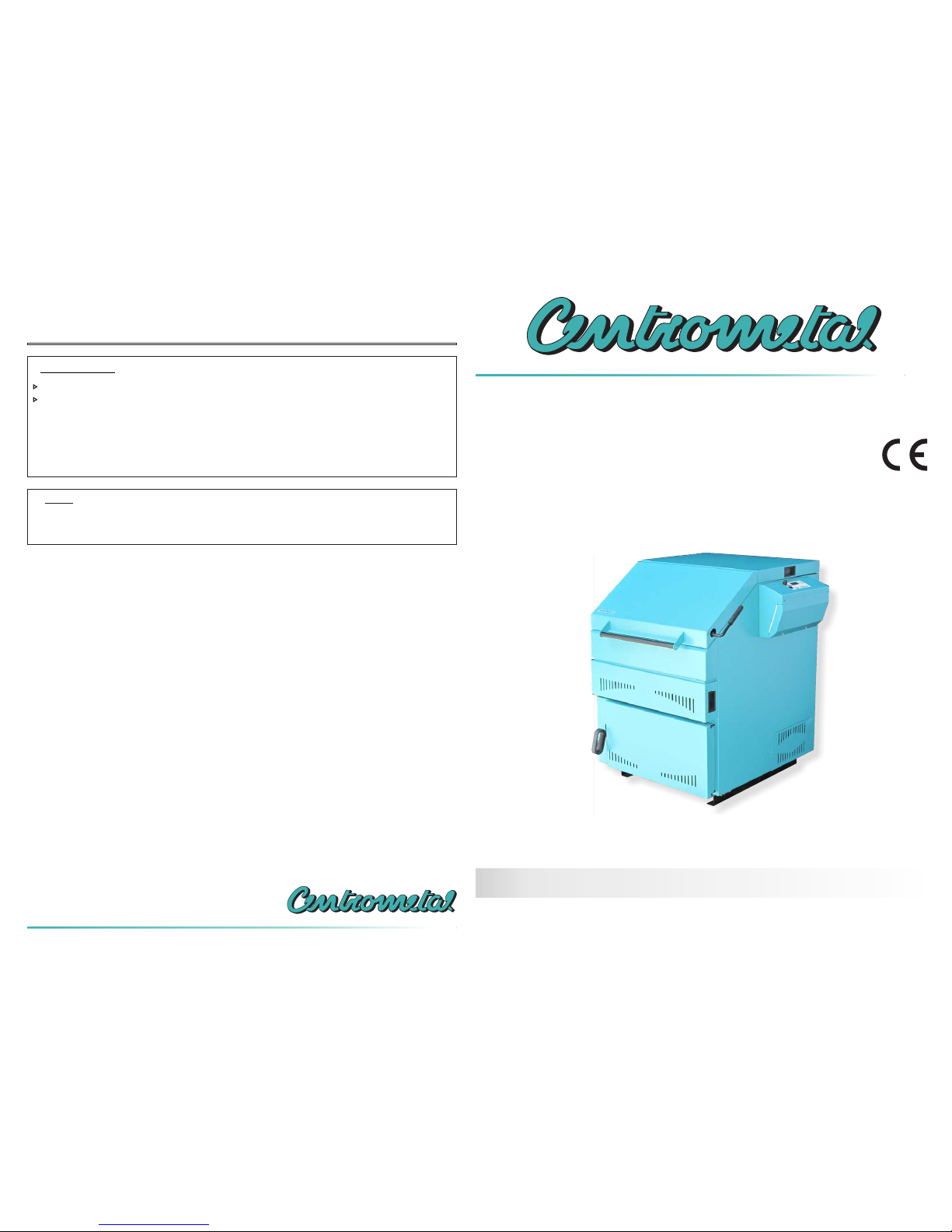
The fuel to be used is only wood under 25% humidity content (wood dried min. 1 year).
The outlet temperature always has to be over 60°C. This can be reached by obligatory connection of the
3-way thermic valve ESBE VTC 512, VTC 531 or Laddomat 21, which blocks the boiler temperature fall
under the 60°C level if the boiler is connected to the central heating system through an appropriate
number of the CAS accumulation tanks or manual 4-way mixing valve if the boiler is connected direct to
the central heating system.
IMPORTANT !
During the process of refilling the fuel the main switch of the boiler and the button ‘’START/STOP’’have
to be turned on.
NOTE:
www.centrometal.hr
e-mail: [email protected]
Centrometal d.o.o. Glavna 12, 40306 Macinec, Croatia
central tel: +385 40 372 600, fax: +385 40 372 611
servce tel: +385 40 372 622, fax: +385 40 372 621
Centrometal d.o.o. shall not be responsible for possible incorrect data caused by printing errors or error made in transcription and all figures and
diagrams are for explanatory purposes only and relevant adjustment have to be made at the spot. In any case, it reserves the right to modify its products
as deemed to be required and useful without any prior notification.
TUCPlus-10_1/2010-eng
BioSolid
TECHNICAL INSTRUCTIONS
for installation, use and maintenance
of hot water boiler
and installation of additional equipment
HEATING TECHNIQUE
Centrometal d.o.o. - Glavna 12, 40306 Macinec, Croatia, tel: +385 40 372 600, fax: +385 40 372 611
HEATING TECHNIQUE
Page 2
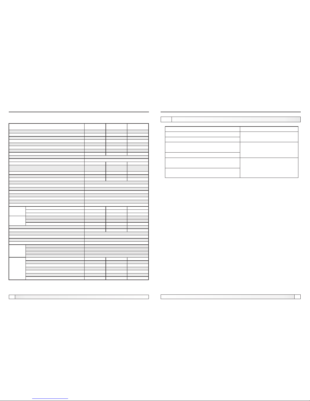
Technical data
Technical data
BioSolid 26
(mm)
max.
330x150x150
BioSolid 17 BioSolid 34
max.
500x150x150
max.
500x150x150
TYPE
Fuel size
26
3
16
72
180
0,026
0,620
10
2,5
wood logs
12-20
80
530x255
91
250
670
596
1050
1070
840
1050
390
430
150
165
340
675
915
450
850
227
(kW)
(Pa)
(lit.)
(°C)
(kg/s)
(kW)
(mbar)
(h)
(%)
(l)
(mm)
(l)
(lit./kW)
(W)
(°/bar)
(V~)
(Hz)
(W)
(mm)
(mm)
(mm)
(mm)
(mm)
(mm)
(kg)
(kg)
(bar)
(bar)
(°C)
(mm)
(R)
(R)
(R)
(R)
(mm)
(mm)
(mm)
(mm)
(mm)
(mm)
(mm)
underpressure
by EN 303-5 point 4.2.5
10-15°C, 2 bar
230
50
~
150
2,5
5,5
90
5/4"
1/2"
3/4"
1/2"
34
3
18
98
180
0,034
0,669
15
12-20
103
530x255
117
736
596
1150
1140
840
1150
489
534
165
340
775
1015
610
950
227
17
3
14
54
180
0,017
0,476
6
12-20
64
370x255
70
670
436
1050
1085
680
1050
288
318
165
340
505
915
450
850
275
Nominal heat output
Boiler class
Required chimney underpressure
Water amount in boiler
Exhaust gas temperature at nominal heat output
Exhaust mass flow at nominal heat output
Standby heat losses
Boiler resistance on water side at nominal output
Combustion period at nominal output
Fuel type
Fuel moisture content
Firebox volume
Wood feeding opening AxB
Combustion chamber volume
Combustion chamber type
Required minimum accumulation next to boiler
Electrical power input
Temp. and press. of water from water supply line into heat exchanger
Supply voltage
Frequency
Current type
Fan power
Boiler body mass
Total mass - (boiler with casing and accessories)
Max. operating overpressure
Test pressure
Max. operating temperature
Uptake tube – external diameter
Dimensions of
the boiler
body
Dimensions
in total
Total depth
Total width
Total height
Lenght
Width
Height
(D)
(E)
(F)
(A)
(B)
(C)
Flow and return pipe (male thread)
Charge/discharge (female thread)
Heat exchanger connector (male thread)
Connector of exchanger sensor (female thread)
H1
H2
H3
H4
H5
H6
L1
Other
dimensions
Boiler
connections
2
31
Technical instructions BioSolid Technical instructions BioSolid
12.0. ERRORS AND POSSIBLE CAUSES
ERROR
E1-1 - short circuit of the boiler sensor
E2-1 - short circuit of flue gas sensor
E2-2 - flue gas sensor interrupted
E3-1 - short circuit of the heating
accumulation tank sensor
E3-2 - heating accumulation tank sensor
interrupted
E1-2 - boiler sensor interrupted
WHAT TO DO
Replace the boiler sensor
Replace the flue gas sensor
Replace the heating
accumulation tank sensor
Errors and possible causes
Page 3
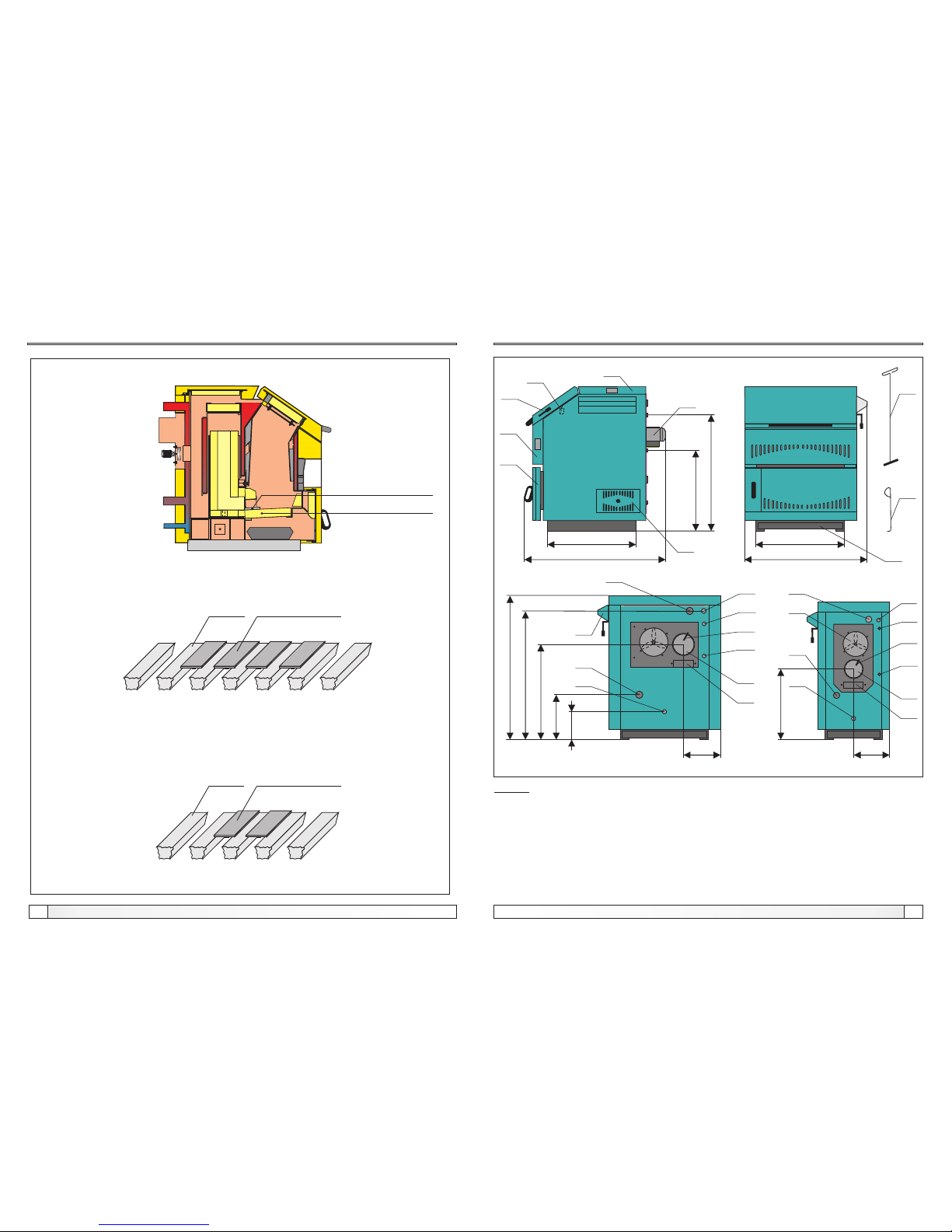
3
Dimensions and basic parts of the boiler
30
LEGEND:
KR - Digital boiler regulation
GV - Upper boiler door for cleaning
VL - Door of the combustion chamber
DV - Lower boiler door
PL - PInlet line
DM - Chimney connection
VT - Fan
PV - Outlet line
PP - Filling / draining
GR - Scraper for cleaning
KA - Heat exchanger connection - draining to the sewage
TO - Thermal safety valve sensor connection
TV - Heat exchanger connection - thermal safety valve connection point
DO - Lower opening for flue gas chamber cleaning / opening for the secondary air
OZ - Air opening lid
OD - Place for the temperature sensor of flue gases
SV - Microswitch
ZP - Zipper
IP - Base protection
Technical instructions BioSolid Technical instructions BioSolid
Grate
Metal sheet for grate
Figure 10. Metal sheets for grate
Grate
Metal sheet for grate
BioSolid 26 / 34 :
BioSolid 17:
Boiler cleaning and maintenance
Grate
Metal sheet for grate
E
B
H1
H2
H4
H3
C=F
D
A
L1
KR
GV
VL
VT
DM
OC
PL
PV
PP
DV
OZ
DO
TV
TO
KA
DM
OC
TV
TO
KA
PV
PP
PL
BioSolid 26 i BioSolid 34 BioSolid 17
VT
H3
H5
H6
L1
SV
OD
OD
GR
ZP
IP
Page 4
4
General, boiler description, delivery, additional equipment
29
1.0. GENERAL
1.1. BOILER DESCRIPTION
1.2. DELIVERY OF BioSolid BOILER
1.3. OBLIGATORY ADDITIONAL EQUIPMENT OF BOILER BioSolid
INSTALLED TO CLOSED CENTRAL HEATING SYSTEM
-Thermal shut off valve (such as CALEFFI 543 513)- 1 piece
Technical instructions BioSolid Technical instructions BioSolid
Hot water boiler BioSolid have modern design, is made of proofed high-quality
materials, welded by state-of-the art technology and meets all requirements for
connection to central heating system.
Steel boilers BioSolid, with an rated thermal output 17, 26, and 34 kW are
constructed for wood firing. They are intended for heating of small and middle sized
premises. Widely sized combustion chamber enables the firing with wood pieces of
500 mm for boilers 26 and 34 kW and 330 mm for boilers 17 kW. One filling period
lasts min. 2 hours, with the possibility of prolonging it to the whole day, if the heating
requirement is decreased. The functioning of the boiler is steered by the built-in
digital regulation system. The boiler must be connected to the central heating
system through an appropriate number of the CAS water accumulators or directly to
the central heating system. Boiler cleaning is very simply and can be done from the
front and back side.
The boiler BioSolid (covered by the casing with an thermal insulation and with builtin the digital boiler regulation), sensor for accumulation tank and scraper for
cleaning (scraper, zipper), base protection.
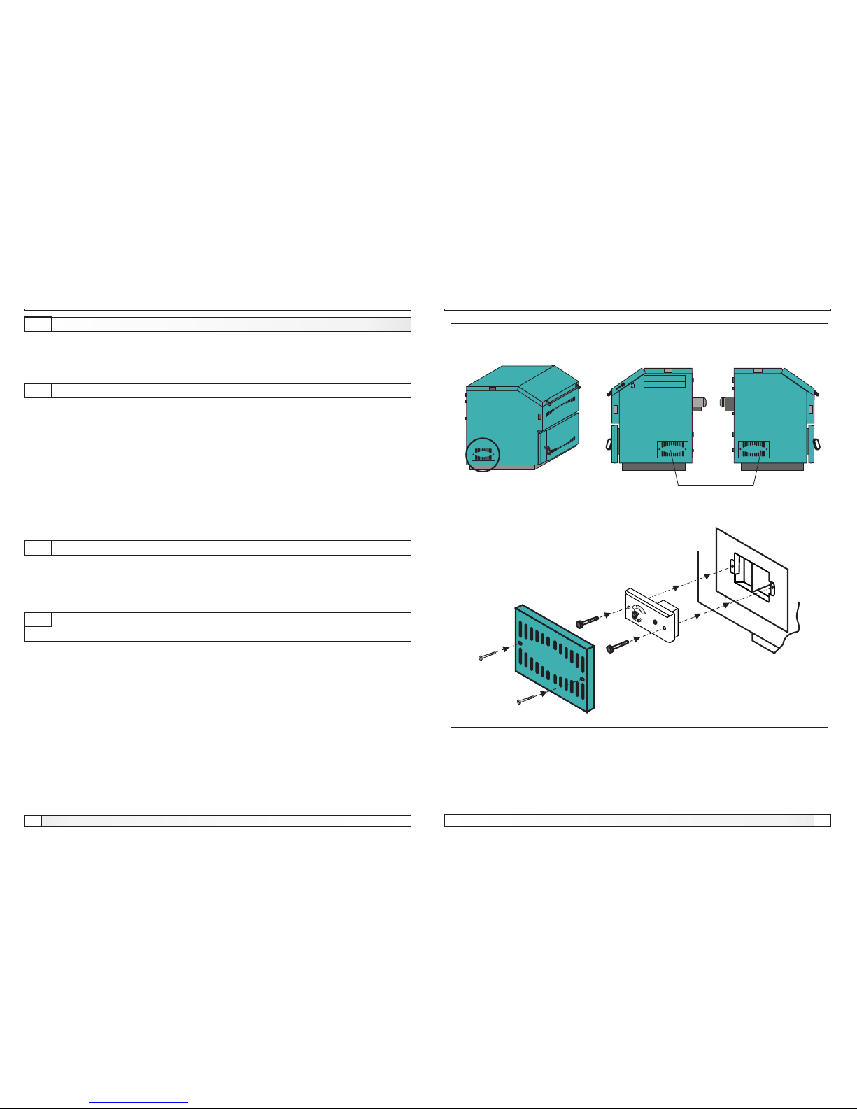
Detail A
Figure 9. Openings for cleaning flue gas chamber
openings for cleaning
flue gas chamber
Boiler cleaning and maintenance
A
Page 5
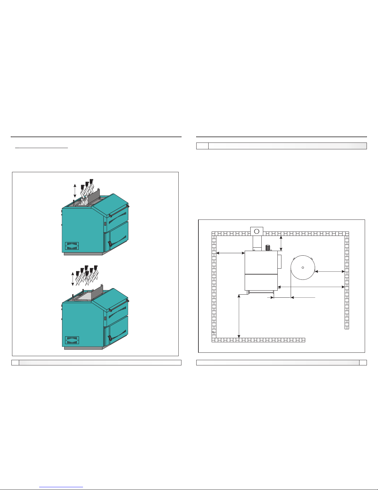
2.0. BOILER POSITIONING AND ASSEMBLY
min. 1000 mm
min.
500
mm
min. 1000 mm*
min. 1500 mm
min. 700 mm*
Figure 1. Minimum distance from the room walls
5
Boiler positioning and assembly
28
min. 1000 mm**
* - If the boiler is installed in the heating system
via the accumulation
** - If the boiler is directly installed on the heating
system
Technical instructions BioSolid Technical instructions BioSolid
The boiler's body is covered by the casing with an thermal insulation on wooden box
and packed in a protective PVC foil. Before placing boiler body onto its location in
the boiler room, it should be removed from palette. Boiler positioning and assembly
and building in of additional equipment must be performed by a qualified person.
We recommend that boiler is placed on a concrete base with height of 50 to 100 mm
above the floor. Boiler room must be frost-proof and well ventilated. Boiler has to be
positioned so that it can be properly connected to the chimney (see point 4.0) and
simultaneously, enabling tending of boiler and additional equipment, control during
operation, and cleaning and maintenance (see Figure 1).
WARNING!
Flammable items must not be placed on the boiler and within the minimum
distances shown in Figure 1.
Figure 8. Extraction turbulators
BioSolid 26
BioSolid 34
Boiler cleaning and maintenance
5.Cleaning of the fan box:
- unscrew two M8 nuts and remove the fan box lid.
- remove ash and impurities from the fan box.
- place back the fan box lid on two M8 screws and tighten them with two M8 nuts to
get good air tightness during operation.
Page 6
6
27
Technical instructions BioSolid Technical instructions BioSolid
11.0. BOILER CLEANING AND MAINTENANCE
Boiler cleaning and maintenance
Protective gloves must be used (see Figure 7).
Ash remaining in boiler after solid fuel firing should be disposed into metal
containers with a cover. First, main switch at boiler control unit has to be turned off.
Combustion chamber have to be clean on daily basis with scraper for cleaning. If
the metal sheet, which that lie on the grid, are clipped or removed at cleaning, they
need be put back (see Figure 10). Flue gas chamber should be cleaned as required.
Fan box should be cleaned as required. Fan blades should be cleaned as required.
Flue ducts should be cleaned as required. Ash tray in the lower boiler part should be
cleaned as required. Checking of all control and safety elements once per year by
authorised serviceman / fitter is recommended.
1. Cleaning a flue ducts
- open the upper boiler door (see Point 8.0 and Figure 5.3)
- take out turbulators from the flue ducts (only for BioSolid 26 and 34) (see Figure 8.)
- with scraper clean a dirt which are stuck on the wall of flue ducts
- bring back turbulators to the flue duct (only for BioSolid 26 and 34) (see Figure 8.)
- close upper boiler door (see Point 8.0 and Figure 5.3, Figure 5.4)
2. Cleaning a combustion chamber:
- combustion chamber can be cleaned through door of the combustion chamber
and the lower boiler door with cleaning set (delivered with boiler)
- take care to clean thoroughly its lateral sides to ensure as better heat exchange
and maximum boiler utilisation rate as possible.
3. Cleaning flue gas chamber:
- flue gas chamber can be clean through side openings (see page3 and Figure 9.)
- remove the cover
- remove the dirts which are stuck during the boiler operation i boiler cleaning
- bring cover back
4. Cleaning of fan blades:
- unscrew four M8 nuts by which the fan flange is fixed to the boiler.
- pull out the fan with the flange along the flange holder and turn it to the left to
access the fan blade.
- then, remove all deposits of ash and impurities from the blade.
- put the fan together with the flange back on four M8 screws and tighten them with
four M8 nuts to get good air tightness during operation.
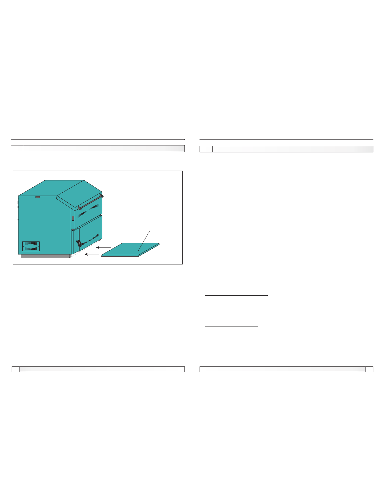
2.1. BASE PROTECTION MOUNTING
Base protection (Page 3, IP) coming with the boiler and it is necessary set
in the provided place after boiler positioning (see Figure 1.1.).
Figure 1.1. Base protection mounting
base protection
Base protection mounting
Page 7
7
26
Technical instructions BioSolid Technical instructions BioSolid
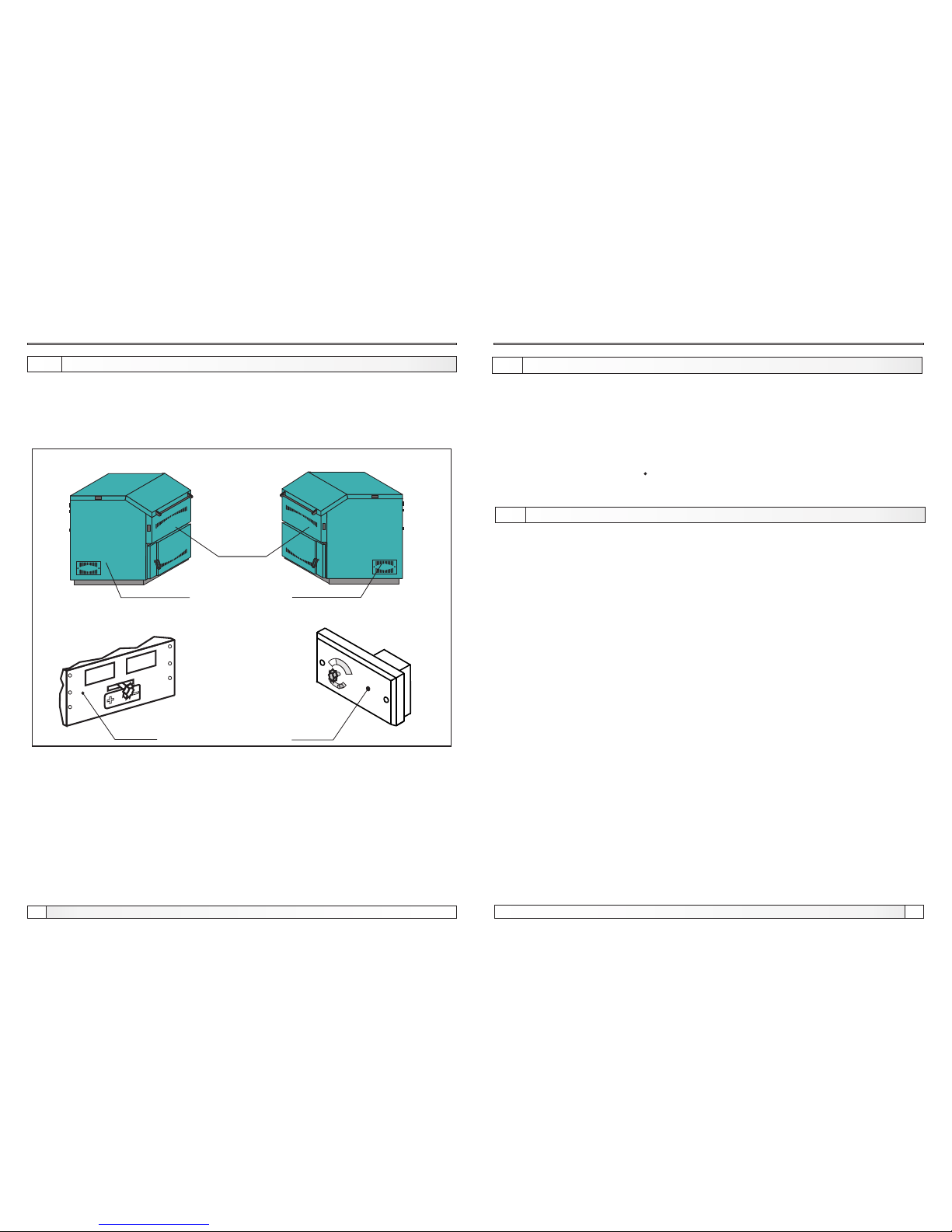
Figure 8. Primary and secondary air setup
Secondary air
Primary air
Secondary air
Manual primary air regulator:
Manual secondary air regulator
10.1. PRIMARY / SECONDARY AIR SETUP
Primary air setup
For the regulation primary or secondary air use MANUAL PRIMARY /
SECONDARY AIR REGULATOR, (see Figure 8).
It is recommended to use the boiler to the factory defaults.
For a possible change in the setting of primary and secondary air is necessary to
remove the screw M5 (Figure 8).
Factory defaultFactory default
Screw M5 Screw M5
4.0. CONNECTION TO CHIMNEY
3.0. MAKE UP AIR OPENING
Make up air opening, connection to chimney
Q - boiler output in kW
2
A - opening area in cm
A = 6,02 Q
Each boiler room must be equipped with an opening for supply of make up air
which is dimensioned in accordance with boiler output (minimum opening area
according to the below shown equation). Such opening must be protected with a net
or grate. All installation works have to be performed in accordance with valid
national and European standards. Boiler must not operate in flammable and
explosive environment.
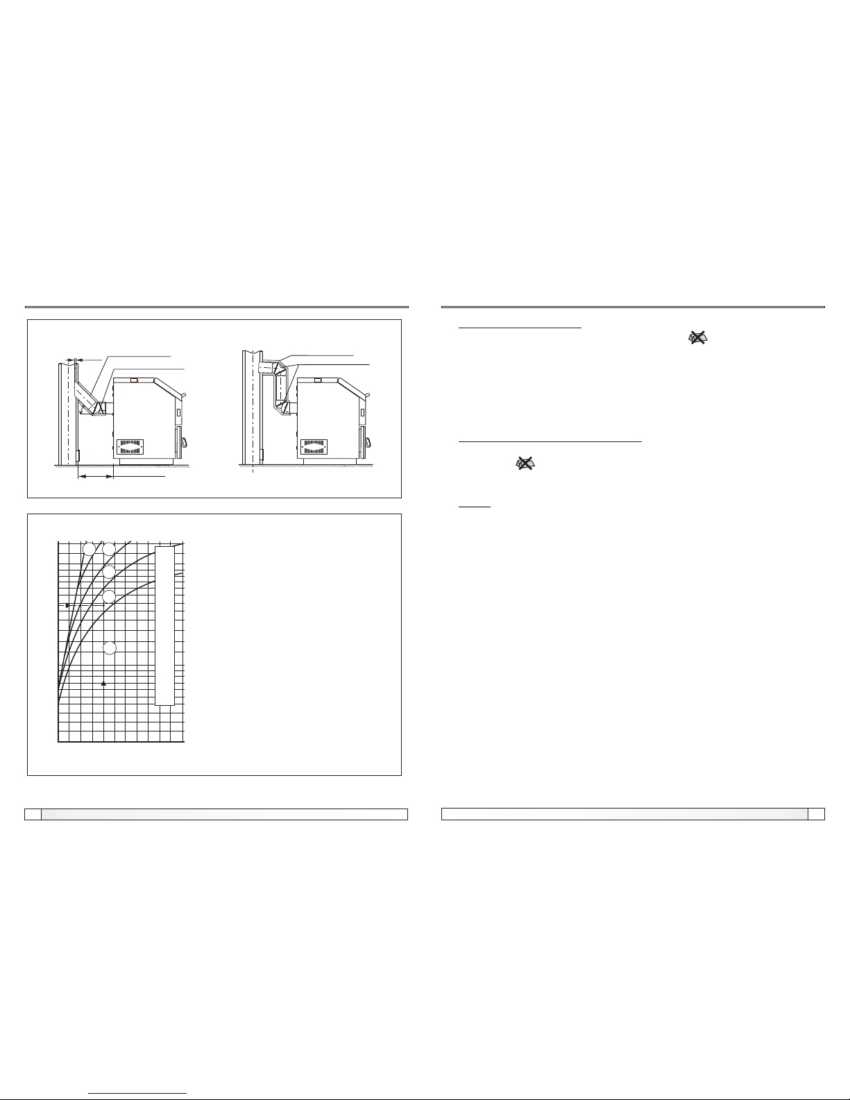
Properly dimensioned and built chimney is a precondition for safe boiler operation
and heating efficiency. A chimney must be thermally insulated, gas-tight and
smooth. Cleaning door must be made in the lower part of a chimney. Chimney made
of bricks must include 3 layers with central insulation layer made of mineral wool.
Thickness of thermal insulation should be min. 30 mm of chimneys is built against to
interior wall, and min. 50 mm if it is built on the outer side. Internal dimensions of
the chimney light diameter depend on chimney height and boiler output and
they have to be selected in accordance with diagram shown in Figure 3. The
chimney usable height is the measure from connection spot of smoke pipe to the
chimney top. As these boilers can be fired with solid fuel, chimney has to be selected
according to the solid fuel diagram. Fuel gas temperature at the chimney exist must
be min. 30°C higher than condensation temperature of combustion gases.
Selection and building of a chimney must be made by a professional. Required
maximum distance from boiler to chimney is 1000 mm, and minimum distance is
500 mm. Uptake tube must be installed at an angle (min. 5°) with a gradient from
chimney to boiler (Figure 2). In order to prevent condensate from chimney to enter
the boiler, uptake tube must be placed 10 mm deeper into chimney. Connecting
uptake tube between boiler and chimney must be thermally insulated with a
mineral wool layer having thickness of 30 to 50 mm.
All installation works must be made in accordance with valid national and European
standards.
Page 8
8
25
Technical instructions BioSolid Technical instructions BioSolid
FUEL REFILLING PHASE:
- After the regulation starts to display the lack of fuel , the fuel should be
refilled (if it is necessary to continue the heating process)-BEFORE REFILLING,
press START button. (see Point 6.1.1).
- open the boiler door of combustion chamber (see point 8.0. and Figure 5.)
- align glow with poker
- insert fuel (recommended to fill the full firebox) (see Figure 6.)
- close the upper boiler door (see point 8.0. and Figure 5.)
TURNING OFF DIGITAL REGULATION:
- If we dont continues with heating proces, after the control indicator-no fuel
switches on , wait until the boiler is cooled down below 65°C and until there
is no glow in the chamber. Only then the main switch on the boiler digital regulation
may be turned off (see 6.1.1.).
NOTE:
During the process of refilling the fuel the main switch of the boiler and the button
‘’START/STOP’’have to be turned on.
Boiler use
Connection to chimney, selection of a chimney
5 10 15
10
15
20
25
30
35
40
45
50
60
6 7 8 9
20
22
2530
18
Figure 3. Chimney dimensioning for boilers BioSolid
Useful chimney height (m)
Boiler nominal output (kW)
Light chimney diameter (cm)
An example of selection of a chimney:
- Boiler heat output: 34 kW
- Fuel: wood
- Required usable chimney height: H = 8 m
- Required chimney light diameter: 20 cm
- Usable chimney height - chimney height
from connection spot of smoke pipe to the
chimney top.
- Light chimney diameter - interior chimney
diameter.
min. 500 mm
max. 1000 mm
10mm
Figure 2. Possible ways of connections of boilers BioSolid to chimney
Thermal insulation
Opening for cleaning
Thermal insulation
Opening for cleaning
RECOMMENDATION
Page 9

9
24
Technical instructions BioSolid Technical instructions BioSolid
Boiler use
Check if the pump of heating system is connected to boiler control unit BioSolid.
Check whether boiler control unit BioSolid is connected to power supply.Fuel with
max. 25% moisture content may be used. Check if the fresh air access to the boiler
room is available (Point 3.0) Check if globe valves toward heating bodies are open.
Check if the safety elements are properly connected and are functioning
perfectly:
- closed central heating systems should have safety valve of max. 2,5 bar, thermal
safety valve and expansion vessel of min. volume which is not less then 10% of the
total water quantity in the system.
- open central heating systems should have an open expansion vessel of min.
volume which is not less then 7% of the total water quantity in the system situated
enough over the level of the highest radiator in the system and insulated, if it is
mounted outside of heated space.
Check if the mobile elements of the boiler are properly positioned:
- sheet metal protecting cover (ZL-Figure 5.2.) have to be fixed to the carriers in the
combustion chamber.
- air damper check if it is able to move.
- primary/secondary air door cover.
- firing has to be performed according to the instructions described in this manual
If you are sure that energy from boiler will be consumed, made firing up for one filling
of the firebox.
IGNITION PHASE AND FIRST FUEL CHARGING:
- Open boiler door of the combustion chamber (and close bottom if they open) (see
point 8.0. and figure 5).
- Put small pieces of wood (chips), crumpled paper then again small pieces of
wood (chips) to the combustion chamber (Figure 6.), on grate trought the door of
the combustion chamber (Figure 6.). To all this put smaller logs (max. 25%
moisture) to max. height 1/2 firebox.
- Close boiler door of the combustion chamber (see point 8.0. and Figure 5.).
- Turn the MAIN SWITCH on.
- Push the button ’’START / STOP’’ (the LED diode light).
- Open the lower boiler door (see point 8.0. and Figure 5.), little back-door behind
the lower boiler door and ignite paper.
- Couple minutes after small pieces of wood (chips) starts burning, close the little
back door and lower boiler door (see point 8.0. and Figure 5.).
- Check whether heating system pump turn on/off at approx. 65°C.
- After about a half hour refill firebox with wood logs (max. 25% moisture).
Installation of boiler to the central heating installation
5.0. BOILER INSTALLATION TO CENTRAL HEATING SYSTEM
5.1. BOILER INSTALLATION TO CLOSED HEATING SYSTEM
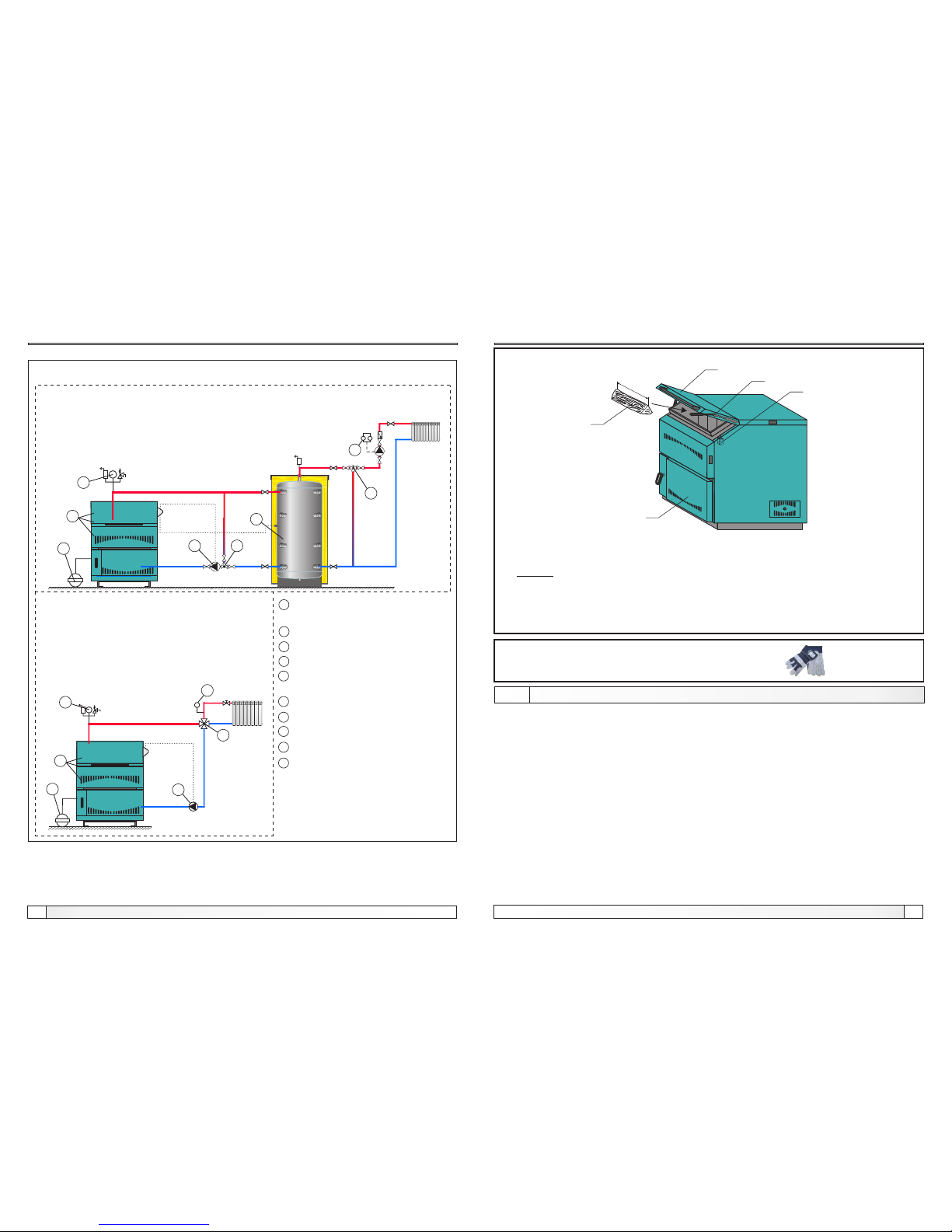
In closed heating system (as in example shown in Scheme 1a and 1b) it is
obligatory to build in certified safety valve with opening pressure of 2,5 bar,
minimum seat diameter of 15 mm, minimum inlet connection of 1/2", minimum exit
connection of 3/4" and a membrane expansion vessel. Safety valve and expansion
vessel must be built in accordance with professional rules and any valve must not
be located between safety valve and expansion vessel and boiler. In all boiler types
the heating pump must be connected to digital boiler regulation BioSolid according
to electric diagram relevant for specific boiler use (point 7 in these instructions) so
that the heating pump switching on and off would depend on water temperature in
the boiler. If boiler is connected to the heating system under Diagram 1b it is
recommended that the environment temperature control is made by a 4-ways
manual mixing valve.
All installation works must be made in accordance with valid national and European
standards.
Boiler BioSolid can be built to closed and open central heating systems. In both
cases boiler can be fired with solid fuel. Installation has to be made, in according to
technical standards, by a professional who will be responsible for proper boiler
operation. Before connecting boiler to central heating system, the system has to be
flushed to remove impurities remaining after system installation. It prevents boiler
overheating, noise within the system, disturbances at a pump and mixing valve.
Boiler should always be connected to central heating system by connectors, never
by welding. Figure 1. shows safe distances required for boiler cleaning and
maintenance.
Page 10
10
23
Technical instructions BioSolid Technical instructions BioSolid
Protective gloves are obligatory!
Figure 7. Protective gloves
Figure 6. Fuel supply method
Note: For opening the boiler doors see point 8.0. and Figure 5.
Fuel supply method, boiler use
10.0. BOILER USE
Boiler must not be used in flammable and explosive environment.
It must not be used by children or disabled persons (either physically or mentally),
as well as by person without knowledge or experience, unless they are under
control or trained by s person responsible for their safety. Children must be
supervised in the vicinity of the product. If the supply cord is damaged, it must be
replaced by the manufacturer, its service agent or similarly qualified persons in
order to avoid a hazard. Protective gloves are obligatory (Figure 7.).
Check whether boiler and equipment are installed and connected in accordance
with these Technical instructions including all points from 1.0 to this 9.0. Check
whether chimney meets requirements of point 4.0 therein. Check whether boiler
room meets all requirements therein. Check if fuel fulfils all requirements therein.
Check whether the boiler and the entire heating system are filled with water and
vented. Check whether safety elements have been correctly installed and in proper
working order (see previous points of instructions). Check whether uptake duct is
sealed and thermally insulated.
-
-
-
-
-
VL
SV
DV
PZ
DR
Boiler door of the combustion chamber
Microswitch
Lower boiler door
Lever for opening / closing the boiler door of the combustion chamber
Wood log
LEGEND:
2
bar
1
3
7
5
8
9
bar
4
1
T
6
9
2
Installation of boiler BioSolid to closed heating system
Scheme 1a. An example of building in of accumulation tank into the central heating
system required under EN 303-5
Shema 1b. An example of building in of
accumulation tank into the central
heating system not required under
EN 303-5
10
10
Closed heating system
1
5
3
4
2
6
7
8
9
-Obligatory installation of air self venting group (safety valve 2,5 bar)
-Room thermostat
-Manual 3-ways mixing valve
-Thermometer
-Thermostat valve-Temperature of
return line min. 60°C
-Thermal protection of boiler
-Manual 4-ways mixing valve
-Accumulation tank (CAS)
-Closed-type expansion vessel
10
-P1 - Pump of the heating system
L
max
SV
PZ
DR
VL
DV
Page 11
11
22
Technical instructions BioSolid Technical instructions BioSolid
IGNITION PHASE AND FIRST FUEL CHARGING:
- Open boiler door of the combustion chamber (and close bottom if they open) (see
point 8.0. and figure 5).
- Put small pieces of wood (chips), crumpled paper then again small pieces of
wood (chips) to the combustion chamber (Figure 6.). To all this put smaller logs
(max. 25% moisture) to max. height 1/2 firebox.
- Close boiler door of the combustion chamber (see point 8.0. and Figure 5.).
- Turn the MAIN SWITCH on.
- Push the button ’’START / STOP’’ (the LED diode light).
- Open the lower boiler door (see point 8.0. and Figure 5.), little back-door behind
the lower boiler door and ignite paper.
- Couple minutes after small pieces of wood (chips) starts burning, close the little
back door and lower boiler door (see point 8.0. and Figure 5.).
- Check whether heating system pump turn on/off at approx. 65°C.
- After about a half hour refill firebox with wood logs (max. 25% moisture).
FUEL REFILLING PHASE:
- After the regulation starts to display the lack of fuel , the fuel should be
refilled (if it is necessary to continue the heating process)-BEFORE REFILLING,
press START button ones, (see point 6.1.1).
- open the boiler door of combustion chamber (see point 8.0. and Figure 5.)
- align glow with poker
- insert fuel (recommended to fill the full firebox) (see Figure 6.)
TURNING OFF DIGITAL REGULATION:
- If we dont continues with heating proces, after the control indicator-no fuel
switches on , wait until the boiler is cooled down below 65°C and until there
is no glow in the chamber. Only then the main switch on the boiler digital regulation
may be turned off (see 6.1.1.).
NOTE:
During the process of refilling the fuel the main switch of the boiler and the button
‘’START/STOP’’have to be turned on.
Start up
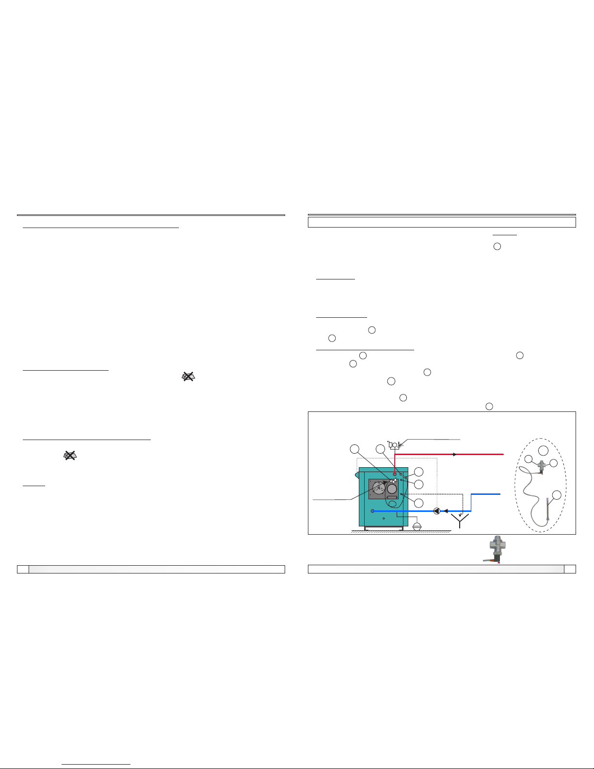
5.1.1. BOILER THERMAL PROTECTION - BioSolid
Boiler thermal protection
According to European EN standards, boiler thermal protection must be installed in closed
heating system. Boiler is factory prepared for installation of thermal protection. Heat
exchanger is built into boiler at factory, and thermal safety valve 2 is installed according to
scheme 2. In case of any damage of boiler installed in the closed heating system due to its
overheating, and boiler or system are not equipped with any thermal protection at all, or do
not have properly installed thermal protection, guarantee will not be applied.
IMPORTANT:
Thermal protection must be connected to the water supply installation of the premises
supplied from the water supply line and not from hydrophor. Namely, in case of failure of
power supply, boiler could be overheated, and then hydrophor is not able to ensure required
water supply.
THERMAL FUSE:
Thermal fuse for boiler BioSolid consists of a heat exchanger which is factory built in boiler,
and thermal valve 2 (such as CALEFFI 543 513) (see Scheme 2.).
Part 2 is installed into prepared connector (male thread 3/4") in the upper back side of boiler.
INSTALLATION (under Scheme 2.)
- Thermal valve 2 is installed onto prepared connector (male thread 3/4") 6
- Connector 5 (female thread 3/4") of thermal valve should be connected to connector of
heat exchanger factory built into boiler 6 (male thread 3/4").
- Thermal valve connector (female thread 3/4") should be connected to cold sanitary
water supply.
- Connector of heat exchanger 7 should be connected sewage system.
- Tighten thermal valve sensor (male thread 1/2") into coupling 1 (female thread 1/2”)
4
bar
7
6
3
2
3
1
2
5
4
Scheme 2. Installation of thermal protection of boiler BioSolid installed
in the closed heating system
FROM WATER
SUPPLY SYSTEM
CONNECTED TO
MUNICIPAL WATER
SUPPLY LINE
Safety valve 2.5 bar
Inlet into central
heating system
Outlet
from
central
heating
system
SEWAGE
* Position of thermal valve after installation:
(valve head downward)
Page 12
12
21
Technical instructions BioSolid Technical instructions BioSolid
9.0. START UP THE BOILER
Start up
Boiler must not be used in flammable and explosive environment.
It must not be used by children or disabled persons (either physically or mentally),
as well as by person without knowledge or experience, unless they are under
control or trained by s person responsible for their safety. Children must be
supervised in the vicinity of the product. If the supply cord is damaged, it must be
replaced by the manufacturer, its service agent or similarly qualified persons in
order to avoid a hazard.Protective gloves are obligatory (Figure 7.).
Check whether boiler and equipment are installed and connected in accordance
with these Technical instructions including all points from 1.0 to this 9.0. Check
whether chimney meets requirements of point 4.0 therein. Check whether boiler
room meets all requirements therein. Check if fuel fulfils all requirements therein.
Check whether the boiler and the entire heating system are filled with water and
vented. Check whether safety elements have been correctly installed and in proper
working order (see previous points of instructions). Check whether uptake duct is
sealed and thermally insulated. Check if the pump of heating system is connected
to boiler control unit BioSolid. Check whether boiler control unit BioSolid is
connected to power supply. Check if the boiler is connected direct to the central
heating system or throught one or more water accumulator/s, through the
appropriate pump/s and 3-way thermic valve ESBE VTC 512, VTC 531 or
Laddomat 21 according to this manual. Fuel with max. 25% moisture content may
be used. Check if the fresh air access to the boiler room is available (Point 3.0)
Check if globe valves toward heating bodies are open. Check if the safety
elements are properly connected and are functioning perfectly:
- closed central heating systems should have safety valve of max. 2,5 bar, thermal
safety valve and expansion vessel of min. volume which is not less then 10% of the
total water quantity in the system.
- open central heating systems should have an open expansion vessel of min.
volume which is not less then 7% of the total water quantity in the system situated
enough over the level of the highest radiator in the system and insulated, if it is
mounted outside of heated space.
Check if the mobile elements of the boiler are properly positioned:
- sheet metal protecting cover (ZL-Figure 5.2.) have to be fixed to the carriers in the
combustion chamber.
- air damper check if it is able to move.
- primary/secondary air door cover.
- metal sheet for grate set to providet place (see Figure 10).
- firing has to be performed according to the instructions described in this manual
Remove all objects like documents/manuals eventually laying inside the boiler.
If you are sure that energy from boiler will be consumed, made firing up for one filling
of the firebox.
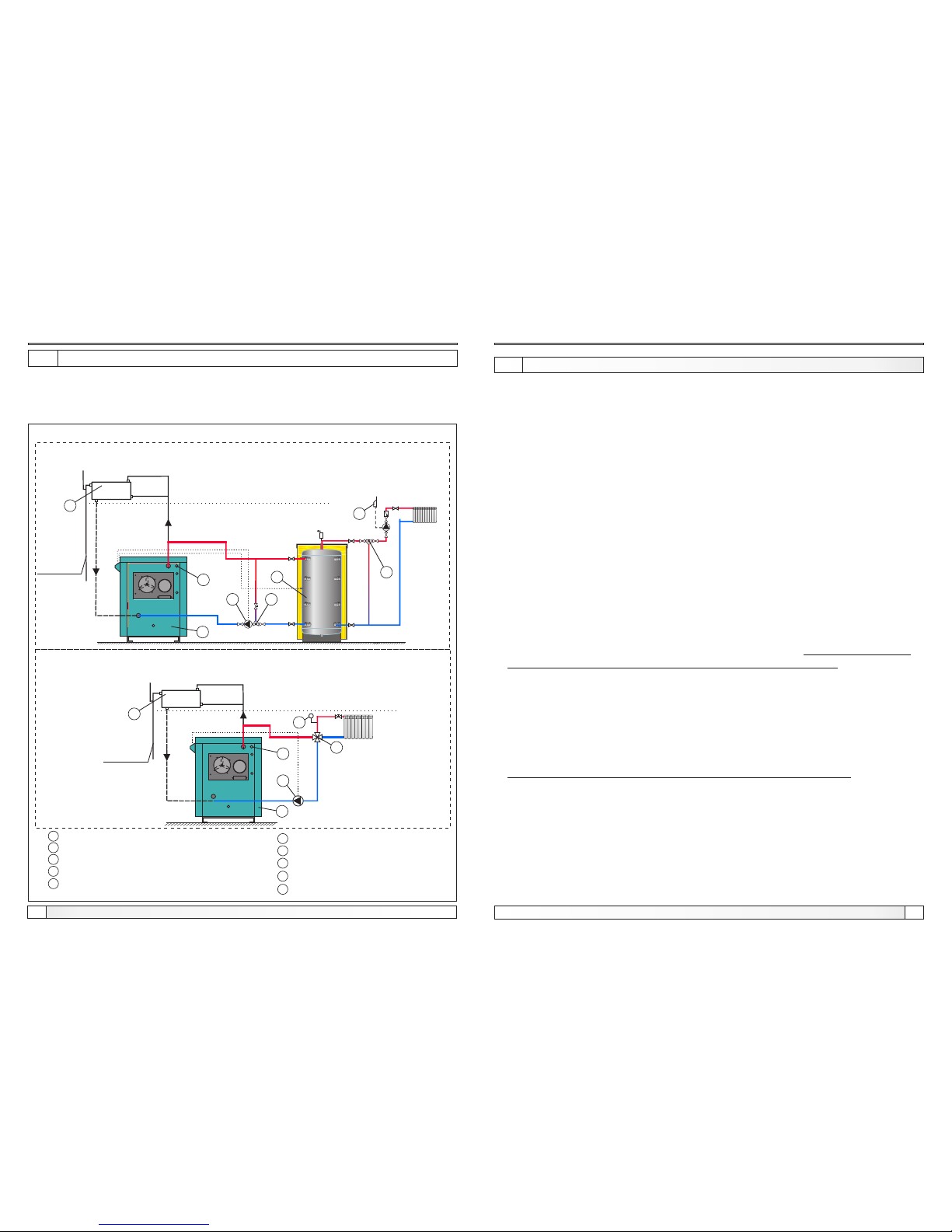
1
-Boiler BioSolid
6
-thermometer
2
3
4
5
-close tightly
-manual 3-ways mixing valve
-manual 4-ways mixing valve
8
7
9
-thermostat valve-ensures temperature
in return pipe min. 60°C
-accumulation tank (CAS)
-room thermostat
-open expansion vessel OPC
10
-P1 - pump of the heating system
5.2. BOILER INSTALLATION TO OPEN HEATING SYSTEM
OPC
9
4
2
5
8
3
7
OPC
9
2
T
6
1
1
Example of installation of boiler BioSolid in an open heating system
Scheme 3a. An example when building in of accumulation tank into the central heating
system required under EN 303-5
ABOVE THE HIGHEST HEATING BODY
U kotlovnicu
Scheme 3b. An example when building in of accumulation tank into the central heating
system is not required under EN 303-5-5
ABOVE THE HIGHEST HEATING BODY
U kotlovnicu
10
10
Open heating system
If boiler is installed in an open central heating system, it is recommended that system is made
according to Scheme 3a or 3b. In open system it is necessary to put an open expansion
vessel above the height of the highest heating body. If expansion vessel is located in a room
without heating, it should be insulated.
Page 13
13
20
Technical instructions BioSolid Technical instructions BioSolid
Figure 5.4. Use the zipper when closing boiler door of the combustion chamber
Detail A
Zipper
Boiler door opening method
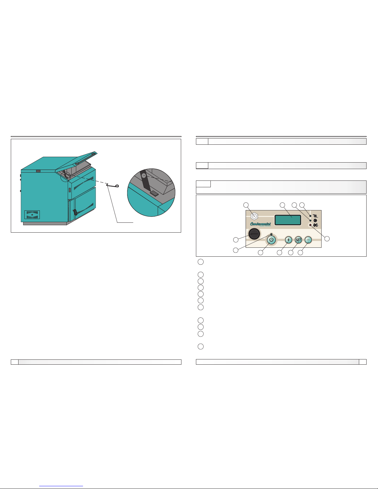
Boiler control unit
6.0. CONTROL OF BOILER TEMPERATURE
6.1. BOILER CONTROL UNIT BioSolid
- ''0/1'' the main switch (power supply switch) has the function to turn on / off the
regulator.
- Indication "START" (LED diode) shows the regulator functioning mode-turn on.
- ''START / STOP" button - turn on / turn off the fan.
- "+" button.
- "SET" button.
- "-" button.
- Indication (LED diode) "NO FUEL" indicates that the temperature of the flue gases
is below the default value after defined elapsed time of fan work.
- Indication "FAN" (LED diode) indicates that the fan is turned on/off.
- Indication (LED diode) "Pump". indicates that the pump P1 is turned on/off.
- The LED display shows the measured temperatures, paramter settings and
detection of possible errors.
- safety thermostat -turn of the supply of electricity to the boiler and turn of boiler
control unit if temperature in boiler exceeds 110°C (+0°C / -9°C)
4
1
5
6
7
8
9
2
10
11
3
Pump of heating system P1 (see scheme 1 and 2) should be connected to boiler
control unit BioSolid which control pump operation and protects boiler against
subcooling.
Fi20
Fi10
1
3
4
5
6
7
89
10
11
2
Figure 4. Control panel of boiler control unit BioSolid
6.1.1. DESCRIPTION OF THE BUTTONS AND LABELS ON BOILER
CONTROL UNIT
If the supply cord is damaged, it must be replaced by the manufacturer, its service
agent or similarly qualified persons in order to avoid a hazard.
A
Page 14
14
19
Technical instructions BioSolid Technical instructions BioSolid
Boiler door opening method
-Lower boiler door
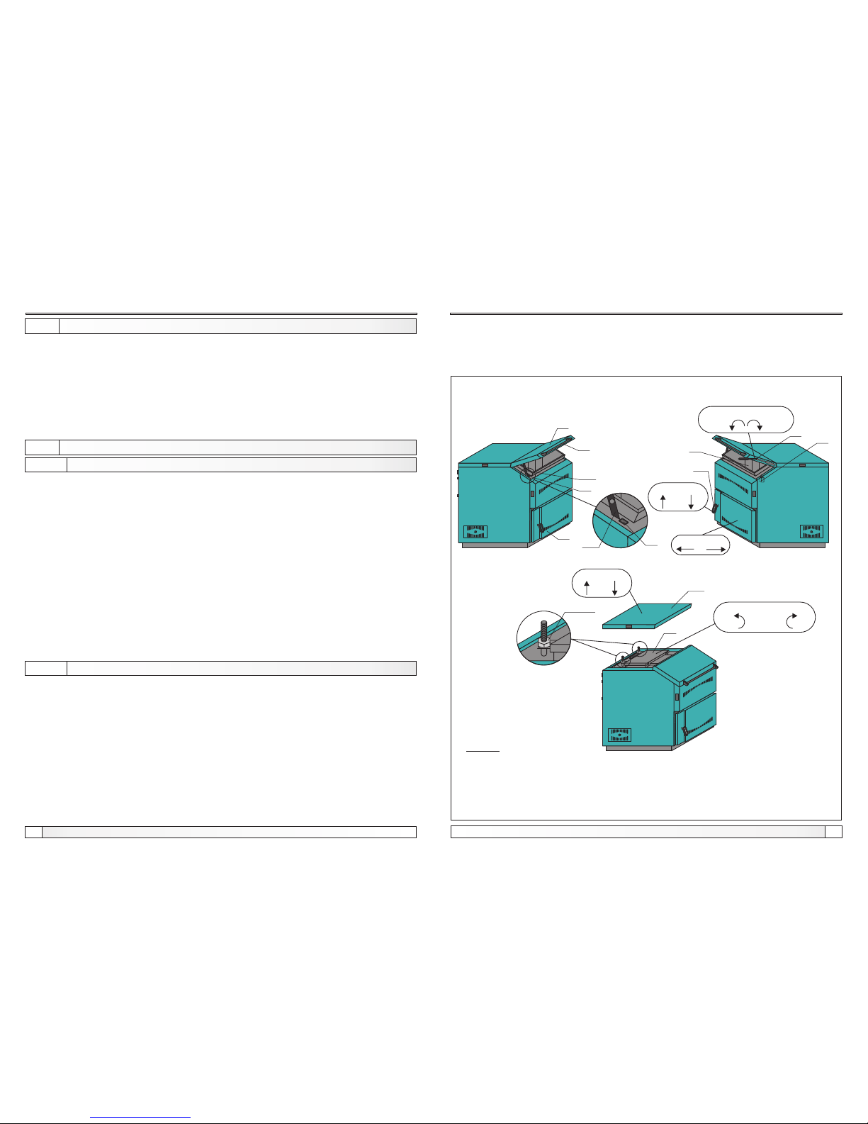
1. Pull the handle of the lower boiler door RDV in the direction of the arrow UP (Figure 5.2).
2. Press the lower boiler door DV in the direction of the arrow right (Figure 5.2).
3. Press the handle of the lower boiler door RDV in the direction of the arrow DOWN (Figure
5.2.) that te the lower boiler door DV is closed.
Figure 5. Boiler door opening method
-
-
-
-
-
-
VL
SV
DV
PZ
GR
RV
Boiler door of the combustion chamber
Microswitch
Lower boiler door
Lever for opening / closing the boiler door
of the combustion chamber
Delimiter
Handle of the boiler door of the combustion chamber
-
-
-
-
-
-
DVL
DR
PGV
GV
RDV
ZL
Holder of the boiler door of the
combustion chamber
Wood log
Cover of the upper boiler door
Upper boiler door
Handle of the lower boiler door
Sheet metal protecting cover
Setting the boiler operating parameter
6.1.2. VIEWING THE MEASURED TEMPERATURE
6.1.3. SETTING THE BOILER OPERATING PARAMETERS
6.1.3.1. BOILER SET TEMPERATURE
6.1.3.2. OTHER PARAMETERS OF THE BOILER OPERATION
For view the measured temperature using buttons ''-'' or ''+'':
-T urn on (1) the main switch (0/1)
- Holding down the button ‘’+’’ on the display is displayed ''_ _ 01''. When we relase
the button ''+'' on the display is displayed flue gases temperature without label °C.
Following holding down the button ''+'' on the display is displayed ''_ _ 02'', when
we relase the button ''+'' on the display is displayed accumulation tank
temperature without label °C. The boiler temperature with label °C is displayed on
the display after the short review. Holding down the button ''-'' the preview goes
reverse way.
Factory setting: 80°C
Available setting: min. 70°C; max. 90°C. When is boiler installed directly on heating
installation (no accumulation tank) (Figure 1b, 3b), adjust a boiler temperature max.
80°C.
Changes procedure of the set temperature of the boiler:
- Turn on (1) the main switch (0/1)
- ''SET'' and ''-'' buttons press 3 seconds, displayed ''P-01'’
- Press the button ''SET'', displayed on the display ''t 80'’
- When we pressed the buttons ''+'' or ''-'' it is posible to change the set boiler
temperature
- Press the button ''SET'', displayed on the display ''P-01'’
-Short press the button ''ON/OFF'' for input confirmation. On the display is
displayed current temperature of the boiler (if the button for change temperature or
''ON/OFF'' button is not pressed within 60 second on the display is displayed
current boiler temperature without input confirmation changes of set boiler
temperature.
FP01 - difference of the boiler temperature at which is the fan again turn on (fan turn
off when the boiler temperature is set and turn on when the boiler
temperature value is lower then set difference), Factory setting: 5°C, set
range 0-8°C.
FP02 - elapsed time from the button ''START'' was pressed or from the boiler door
was opened / closed or from the fan achieved set boiler temperature and
turned off / turned on or from the fan achieved flue gas temperature (250°C)
and turned off / turned on to beginning of comparing flue gas temperature
with boiler temperature - when is flue gas temperature is lower then water
temperature in the boiler, the fan turn off, and LED diode ''NO FUEL'’ turning
on. Factory setting: 120 (minutes), set range 0-180 (minutes).
OPEN
CLOSED
SV
VL
DV
PZ
GR
RV
GR
DVL
DVL
A
Detail A
Figure 5.1
Figure 5.2
UP
DOWN
Figure 5.3
Detail B
RDV
LEFT RIGHT
CLOSED OPEN
PGV
GV
B
Nut M10
LEGEND:
ZL
UP
DOWN
Page 15

18
15
Technical instructions BioSolid Technical instructions BioSolid
8.0. BOILER DOORS OPENING METHOD
Door opening method
Protective gloves are obligatory (Figure 7.)!
BOILER DOORS OPENING METHOD:
- Boiler door of the combustion chamber
1. Pull the lever for opening / closing the boiler door of the combustion chamber PZ in the
direction of arrow OPEN (Figure 5.2.).
2. Catch the handle of the boiler door of the combustion chamber and the door slightly open,
leave them as a couple seconds to fan draw smoke through short circuit and open them
up to the required height that the holder of the boiler door of the combustion chamber DVL
can recline on the delimiter GR (Figure 5.1., detail A).
3. Easy take down boiler door of the combustion chamber VL so that the holder of the boiler
door of the combustion chamber DVL hook to the delimiter GR (Figure 5.1., detail A).
- Upper boiler door
1. Remove the cover of the upper boiler door PGV in the direction of the arrow UP
(Figure 5.3).
2. Remove the two nuts M10 and washers (Figure 5.3., Detail B) which are attached the
upper boiler door GV.
3. Open the upper boiler door GV in the direction of arrow OPEN (Figure 5.3).
- allowed to open only at the stage of cleaning of the boiler and boiler parts.
- Lower boiler door
1. Pull the handle of the lower boiler door RDV in the direction of the arrow UP (Figure 5.2).
2. Open lower boiler door DV in the direction of arrow LEFT (Figure 5.2).
- allowed to open only at the stage of ignition phase of the boiler, cleaning of the boiler and
boiler parts.
BOILER DOORS CLOSING METHOD:
- Boiler door of the combustion chamber
1. Catch with the right hand handle of the boiler door of the combustion chamber RV and
boiler door of the combustion chamber VL pull up slightly, and with left hand and with zipper
slip away (draw to yourself) holder of the boiler door of the combustion chamber DV
(Figure 5.1.,Detail A, Figure 5.4, Detail A).
2. Take down lower boiler door of the combustion chamber VL to heights in which freely
released holder of the boiler door of the combustion chamber DV can not hook the
delimiter GR, let off the holder of the boiler door of the combustion chamber DV and close
the boiler door of the combustion chamber VL.
3. Catch with the left hand the handle of the boiler door of the combustion chamber RV, press
down the boiler door of the combustion chamber VL and close them with lever for opening
/ closing the boiler door of the combustion chamber PZ in the direction of arrow CLOSED
(Figure 5.2)..
-Upper boiler door
1. Close the upper boiler door GV boiler in the direction of arrow CLOSED (Figure 5.3).
2. Mounting the two nuts M10 and washers (Figure 5.3., Detail B) to attach the upper
boiler door GV.
3. Put the lid of the upper boiler door PGV in the direction of arrow DOWN (Figure 5.3.).
6.1.3.3. RESETTING THE BOILER CONTROL UNIT TO FACTORY SETTING
6.1.4. RELAY TEST
Other parameters of the boiler operation, resetting to factory setting, relay test
FP03 - Select operation (1) with or (0) without tempertaure sensor of heating
accumulation tank, factory setting on (1).
- turn off (0) the main switch (0/1).
- holding down button ''SET'' and main switch (0/1) turn on (1). On the display
is displayed ''pin''.
- press the button ''SET''. On the display is displayed 4 lines-down, and left line
flashing. Pressing on the buttons ''+'' or ''-'' we enter numbers, and pressing
on the button ''SET'' we confirm each digit, and move to the next digit.After
confirming the last digit on the display is displayed ''FP01''. Pin is 1234.
- press the button ''SET'' on the display is displayed value FP01.
- pressing on the buttons ''+'' or ''-'' is posible to change the value Fp01.
Values flashing when they are not factory.
- press the button ''SET'', on the display is displayed FP02.
- pressing on the buttons ''+'' or ''-'' is possible to change the value Fp02.
Values flashing when they are not factory.
- press the button ''SET'', on the display is displayed FP03.
- pressing on the buttons ''+'' or ''-'' is posible to change the value Fp03.
Values flashing when they are not factory.
- press the button ''SET'', on the display is displayed FP01 and so goes to the
circle.
- Short press the button ''ON/OFF'' for input confirmation. On the display is
displayed current temperature of the boiler (if the button for change
temperature or ''ON/OFF'' button is not pressed 60 seconds on the display is
displayed current boiler temperature, without input confirmation changes.
- turn off (0) the main switch (0/1)
- holding down button ''+'' and main switch (0/1) turn on (1). On the display is
displayed ''FS'' and a few second is displayed current boiler temperature.
- turn off (0) the main switch (0/1)
- holding down button ''ON/OFF'' and main switch (0/1) turn on (1). Fan starts to
work, light LED diode ''FAN'', on the display is displayed tESt. By pressing the
buttons ''+'' or ''-'' we select pump relay, light diode ''PUMP'' and so goes to the
circle (if the buttons is not pressed within 60 seconds the relay test be over
automatically and on the display is displayed current boiler temperature.
Page 16
16
17
Connection to electrical installations
Technical instructions BioSolid Technical instructions BioSolid
7.0. CONNECTING BOILER TO ELECTRICAL INSTALLATIONS
All electrical works must be performed by a certified professional in accordance
with valid national and European standards.
If the supply cord is damaged, it must be replaced by the manufacturer, its service
agent or similarly qualified persons in order to avoid a hazard.
A device for switching of all power supply poles must be installed in electrical
installation in accordance with the national regulations on electrical installations.
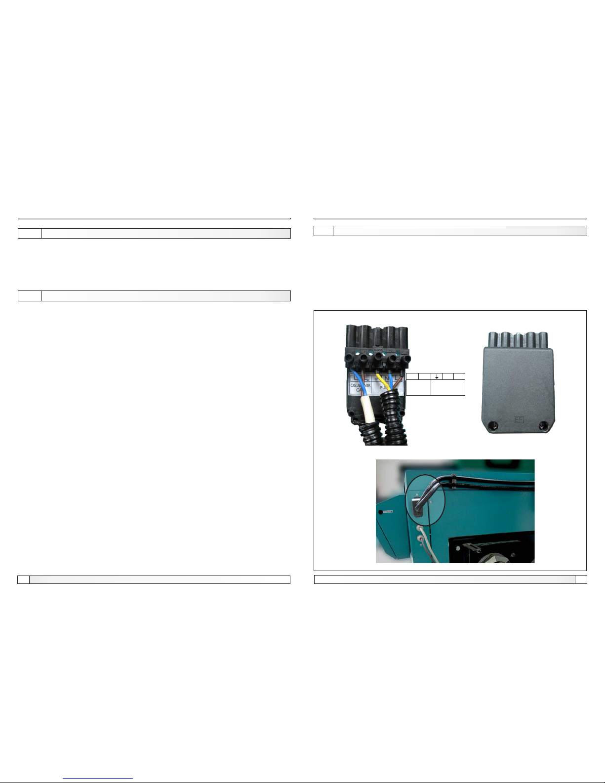
Pump of heating system should be connected to boiler control unit BioSolid
(5-bit connector on the back side of boiler)
6.1.5. ELECTRIC POWER SUPPLY INTERRUPTION
6.1.6. POSSIBLE ERRORS
Power suply interruption, posibile errors
If the electric power supply is interrupted while the boiler is operating (ON) after the
supply is re-established the boiler continues its operation.
If druing the operation phase of the boiler (ON) the main switch (0/1) has been
turned to off (0), after the new activation of the main switch (1) the boiler will work like
the electric power supply is re-established - the boiler continues its operation.
By errors on the display is dispayed label of the errors:
E1-1 - short circuit of the boiler sensor
E1-2 - boiler sensor interrupted
Fan operation disabled, pump works normally
E2-1 - short circuit of flue gas sensor
E2-2 - flue gas sensor interrupted
Fan operation disabled, pump works normaly
E3-1 - short circuit of the heating accumulation tank sensor
E3-2 - sensor of heating accumulation tank interrupted
Fan and pump works normally, reading the temperature of heating
accumulation tank impossibile
Figure 4. - Connecting pump and accumulation tank temperature sensor
L1 L2 N
L3
SENSOR
CAS
PUMP
 Loading...