

Page 1
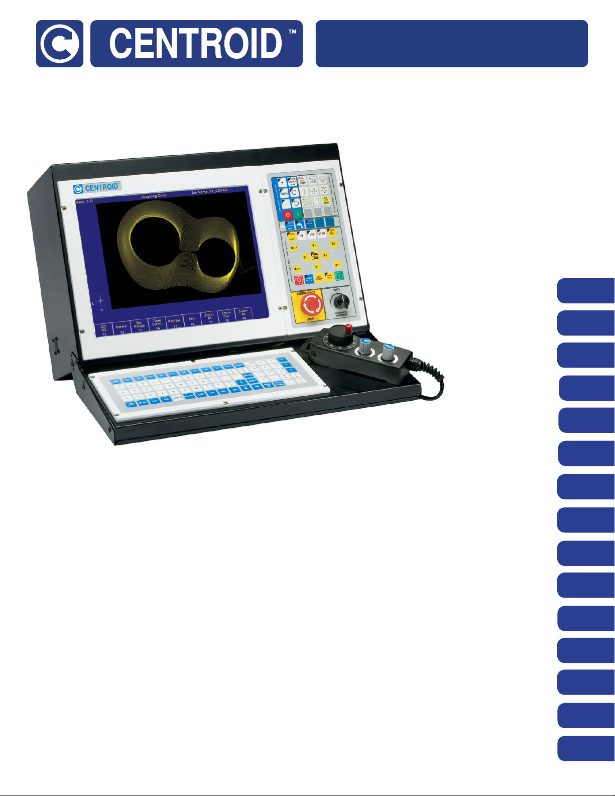
Centroid M-Series Operators Manual
CNC Software version: CNC11 V.3.12
Models: M400 & M39
M400 & M39
Operators Manual
Introduction
Operators Panel
Main Screen
Part Setup
Tool Setup
Running a Job
Utility Menu
Digitizing
Probing
1-1
2-1
3-1
4-1
5-1
6-1
7-1
8-1
9-1
Intercon Conversational Programming
www.centroidcnc.com
v3.12_CENTROID_mill_operators_manual.pdf 12-20-2013 Copyright © 2013-2014 CENTROID
U.S. Patent #6490500
CNC Program codes
G- Codes
M code functions
Conguration
CNC Software Messages
10-1
11-1
12-1
13-1
14-1
15-1
Page 2
READ THIS MANUAL BEFORE USING THIS PRODUCT.
FAILURE TO FOLLOW THE INSTRUCTIONS AND SAFETY
PRECAUTIONS IN THIS MANUAL CAN RESULT IN
SERIOUS INJURY OR DEATH.
All operators and service personnel must read this manual before operating
CENTROID CNC control equipment and all connected machine tools.
Keep this manual in a safe location for future reference.
Throughout this manual and on associated products where applicable, in accordance with
ANSI Z535, the following symbols and words are used as defined below:
DANGER
WARNING
CAUTION
NOTICE
Information provided by CENTROID relating to wiring, installation, and operation of CNC
components is intended as only a guide, and in all cases a qualified technician and all
applicable local codes and laws must be consulted. CENTROID makes no claims about the
completeness or accuracy of the information provided, as it may apply to an infinite number of
field conditions.
“DANGER” with or without a red background =
Hazard WILL cause death or serious injury if
ignored.
“WARNING” with or without an orange
background = Hazard COULD cause death or
serious injury if ignored.
“CAUTION” with or without a yellow
background = Hazard MAY cause minor to
moderate injury if ignored.
“NOTICE” with or without a blue background =
Indicates an action to prevent damage to the
product or other materials used with product.
As CNC control products from CENTROID can be installed on a wide variety of machine tools
NOT sold or supported by CENTROID, you MUST consult and follow all safety
instructions provided by your machine tool manufacturer regarding the safe operation
of your machine and unique application.
Page 3
CENTROID CNC controls provide facilities for a required Emergency Stop circuit which can
be used to completely disable your machine tool in the event of an emergency or unsafe
condition. Proper installation of your CNC control MUST include the necessary wiring
to disable ALL machine tool movement when the Emergency Stop button is pressed.
This includes machine, servo motors, tool changers, coolant pumps, and any other moving
parts. DO NOT disable or alter any safety feature of your machine or CNC control.
Never alter or remove any safety sign or symbol from your machine or CNC control
components. If signs become damaged or worn, or if additional signs are needed to
emphasize a particular safety issue, contact your dealer or CENTROID.
CNC Control Operating Specifications
Minimum Maximum
Operating Temperature 40°F (5°C) 104°F (40°C)
Ambient Humidity 30% relative, non-condensing 90% relative, non-condensing
Altitude 0 Ft. (Sea Level) 6000 Ft. (1830m)
Input Voltage (110, 220, 440 VAC,
System Dependent)
Note: Your machine may have operating conditions different than those shown above. Always consult your
machine manual and documentation.
-10% of Specified System Input
Voltage
+10% of Specified System Input
Voltage
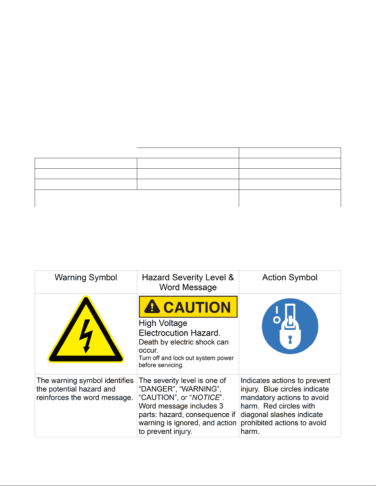
Safety signs and labels found on your machine tool, and on CNC system
components typically follow the following examples:
Page 4

CNC Machine Tool Safety
•All machine tools contain hazards from rotating parts; movement of belts, pulleys, gears, and chains;
high voltage electricity; compressed air; noise; and airborne dust, chips, swarf, coolant, and lubricants.
Basic safety precautions must be followed to reduce the risk of personal injury and property damage.
•Your local safety codes and regulations must be consulted before installation and operation of your
machine and CENTROID CNC control. Should a safety concern arise, always contact your dealer or
service technician immediately.
•Access to all dangerous areas of the machine must be restricted while the machine is in use. Ensure
that all safety guards and doors are properly in place during use. Automatically controlled machine
tools may start, stop, or move suddenly at any time. Do not enter the machining area when the
machine is in motion; death or severe injury may result.
•Personal protective equipment, particularly ANSI-approved impact safety glasses and OSHAapproved hearing protection must be used. Proper handling, storage, use, and disposal of materials
in accordance with manufacturer's instructions and Material Safety Data Sheets (MSDS, or your local
equivalent) must be followed.
•DO NOT operate your machine or CNC control in explosive atmospheres or in environmental
conditions outside of the manufacturer's specified ranges. Electrical power must meet the
specifications provided by your machine and CNC control manufacturer.
•DO NOT operate your machine or CNC control if any safety systems are damaged or missing.
Excessively scratched or damaged windows and guards must be replaced.
•ONLY authorized personnel should be allowed to operate the machine and CNC control. Improper
operation can cause injury, death, and machine or control damage, and may void applicable
warranties.
•All electrical enclosures and panels MUST be closed and secured at all times except during
installation and service. Only qualified electricians and service personnel should have access to these
locations. Hazards arising from high voltage electricity and heat exist in the control cabinet, and may
exist even after the main disconnect is turned OFF.
•Improperly clamped or fixtured parts; improperly secured tooling; and broken parts, fixtures, and
tooling resulting from machining operations at unsafe feedrates and speeds may result in projectiles
being ejected from your machine, even through safety systems such as guards and doors. Always
follow safe and reasonable machining practices and follow all safety precautions provided by your
tooling and machine manufacturer.
•Ultimate responsibility for safe operation and maintenance of your machine and CNC control rests
with shop owners and machine operators. Before performing any work or maintenance all individuals
should be thoroughly acquainted with the safe operation of BOTH machine tool AND CNC control.
•Shop owners and operators are responsible for ensuring that shop and machine safety systems such
as Emergency Stop and fire suppression systems are present and functioning properly, as required by
local codes and regulations.
Page 5
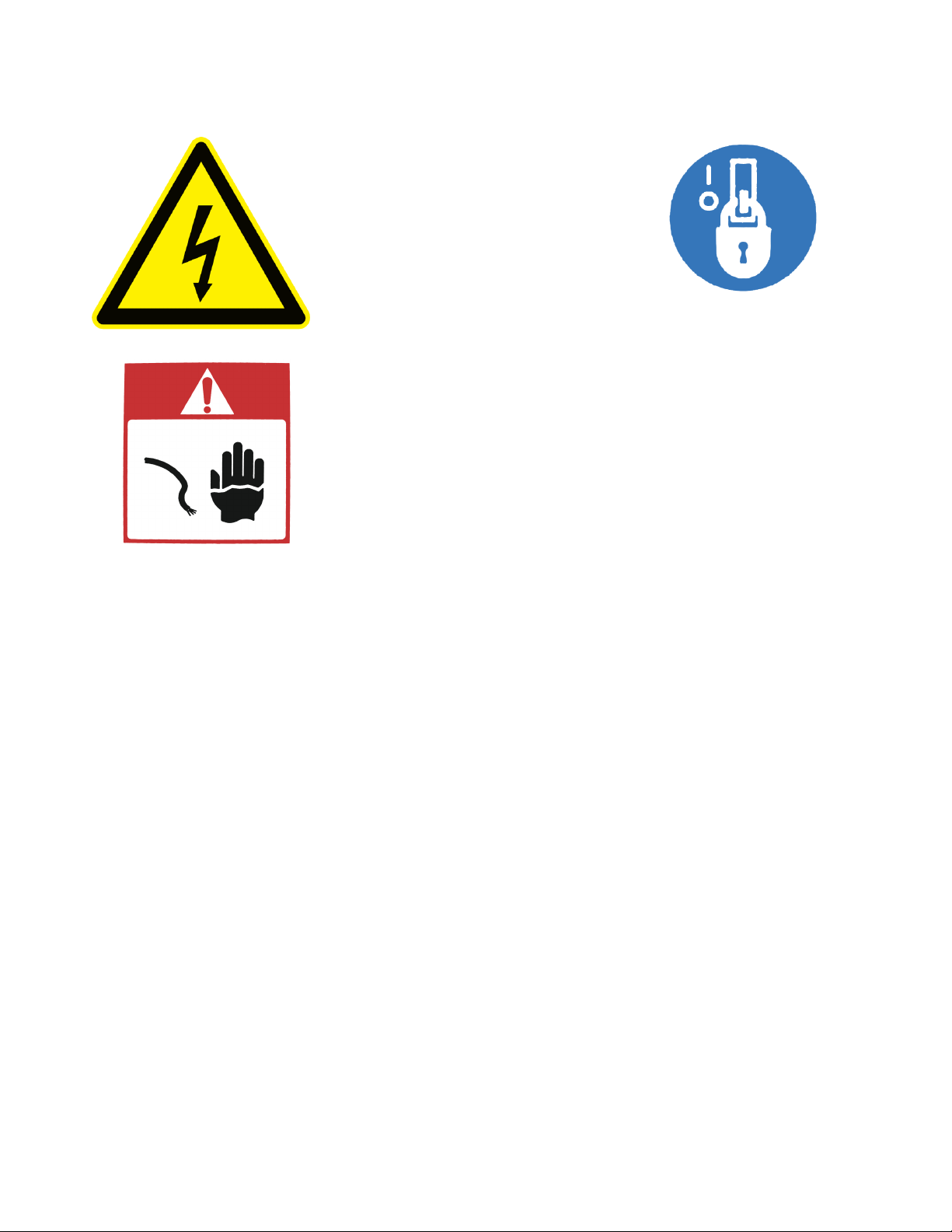
CNC Control Warning Labels
High Voltage Electrocution
Hazard.
Death by electric shock can occur.
Turn off and lock out system power before
servicing.
High Voltage Electrocution
Hazard.
Death by electric shock can occur.
Turn off and lock out system power before
servicing.
Page 6

TABLE OF CONTENTS
CHAPTER 1 - Introduction
Window Description 1-1
Conventions 1-3
Machine Home 1-4
Mill M and G Codes 1-5
Software Unlocks 1-6
CHAPTER 2 - Operator Panels
M-Series Jog Panel 2-1
Keyboard Jog Panel 2-5
Keyboard Shortcut Keys 2-7
CHAPTER 3 – CNC Software Main Screen
Option Descriptions 3-1
CHAPTER 4 - Part Setup
Operation Description 4-2
Part Setup Examples 4-4
Work Coordinate Systems Configuration 4-6
Coordinate Systems Rotation 4-7
Transformed WCS 4-8
CHAPTER 5 - Tool Setup
Offset Library 5-1
Automatic Tool Measurement 5-3
Setting up Tool Height Offsets 5-4
Tool Library 5-5
Tool Life Management 5-7
CHAPTER 6 – Running a Job
Job Run Screen with G-code Display 6-1
Run-Time Graphics 6-2
Canceling a Job in Progress 6-2
Resuming a Canceled Job 6-3
Run Menu 6-3
Power Feed 6-5
CHAPTER 7 - The Utility Menu
F2 – Update, F3 – Backup, F4 – Restore 7-1
F5 - File Ops. 7-2
F6 – User Maint, F7 – Report 7-3
F8 – Options, F9 – Logs 7-3
CHAPTER 8 – Digitize
Grid Digitize 8-2
Radial Digitize 8-6
Contour Digitize 8-10
Wall Following Digitizing 8-13
Dig to CAD 8-15
CHAPTER 9 - Probing
Part Setup with Probing 9-1
Calibrating the Probe Tip Diameter 9-2
Probing Cycles 9-2
Probe Parameters 9-7
DSP Probe Parameters 9-8
CHAPTER 10 - Intercon Software
Intercon Main Screen 10-1
File Menu 10-2
Rapid Traverse 10-7
Linear Mill 10-8
Arc Mill 10-10
Tool Functions 10-12
Canned Cycles 10-13
Drilling 10-16
Chip Breaking 10-17
Deep Hole Drilling 10-19
Boring 10-20
Tapping 10-22
Facing 10-24
Rectangular Pocket 10-25
Circular Pocket 10-27
Rectangular/Circular Frame Milling 10-29
Thread Milling 10-31
Cleanout 10-33
Subprograms 10-36
Repeat to Depth 10-38
Repeat 10-39
Mirror 10-40
Rotate 10-41
Graphics 10-42
Math Help 10-45
Importing DXF files 10-52
Intercon Tutorials 10-59
CHAPTER 11 – CNC Program Codes
Miscellaneous CNC Program Symbols 11-1
User and System Variables 11-5
Advanced Macro Statements 11-8
CHAPTER 12 - G-codes
G-Code Quick Reference 12-1
G-Code Descriptions 12-2
CHAPTER 13 - M functions
M function Quick Reference 13-1
Customizable M functions 13-2
M function Descriptions 13-3
CHAPTER 14 – Configuration
Password 14-1
Control Configuration 14-2
User Specified Paths 14-3
Machine Configuration 14-4
Machine Parameters 14-8
PID Menu 14-42
DSP Probe Configuration 14-45
Smoothing 14-47
CHAPTER 15 – CNC Software Messages
CNC Software Message Descriptions 15-1
Page 7

Page 8
Chapter 1
Introduction
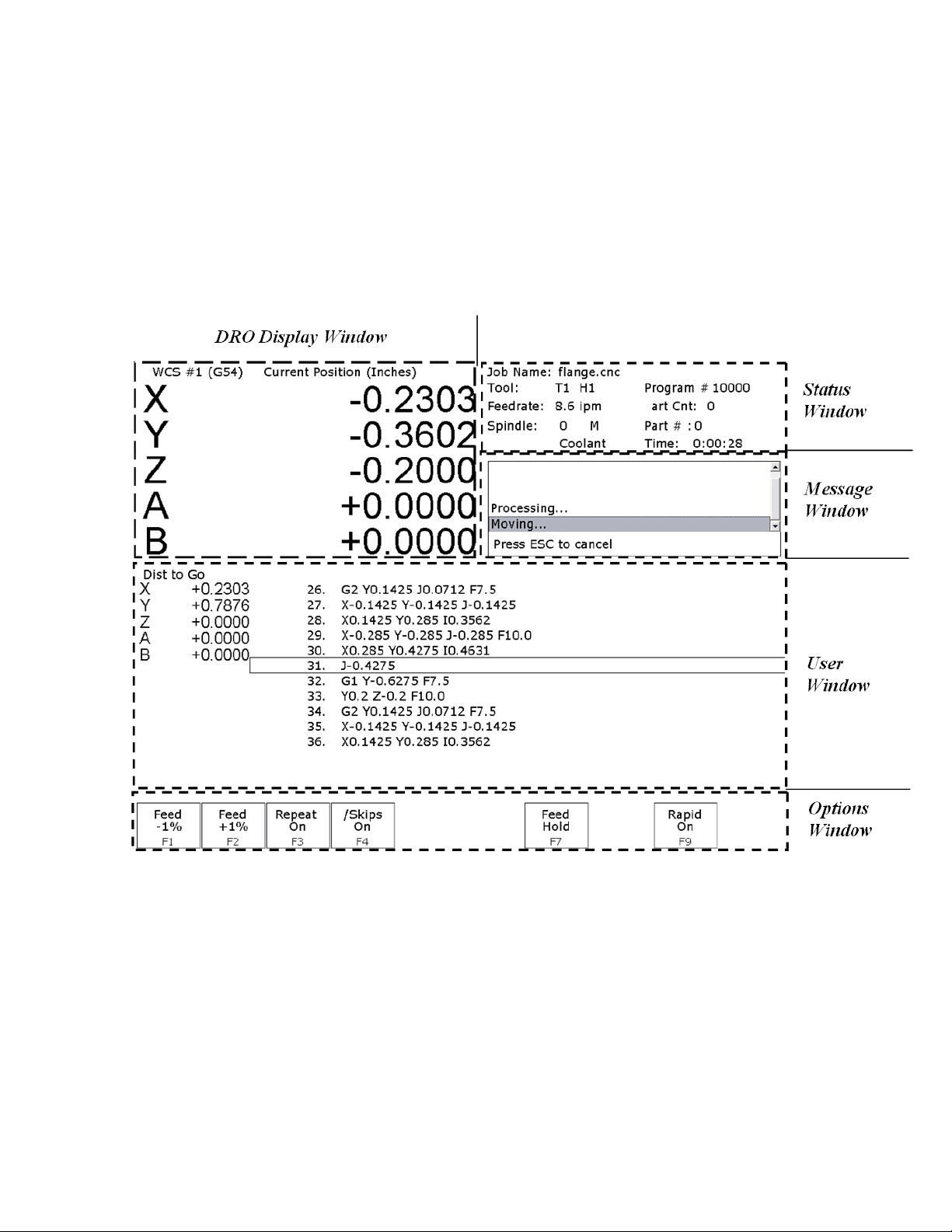
Window Description
The CNC software display screen is separated into five areas called windows. A sample screen is shown below for
reference. The five windows are the DRO display window, the status window, the message window, the options
window, and the user window. The information that each window displays is described in detail in the following
sections.
DRO display
The DRO display contains the digital read out of the current position of the tool. The display is configurable for
number of axes and desired display units of measure (see Chapter 14). The bars under each axis are the load meters
and represent the amount of power being supplied to the drive for that axis. The display of axis load meters is
configured by machine parameter 143 – see Chapter 14 for specific information.
Distance to Go DRO
The distance to go DRO is located below the main DRO. This display shows the distance to go to complete the
current movement. The display of distance to go is controlled by parameter 143. See Chapter 14 for details. See
also “Hot Keys” in chapter 2.
M-Series Operator’s Manual 12/20/13 1-1
Page 9

Status window
The first line in the status window contains the name of the currently loaded job file. Below the job name are the
Tool Number, Program Number, Feedrate Override, Spindle Speed, and Feed Hold indicators. The Feedrate
Override indicator displays the current override percentage set on the Jog Panel. The Feedrate label will turn RED
if the rapid override is turn off. If your machine is equipped with a variable frequency spindle drive (inverter), the
Spindle indicator will display the current spindle speed. The Feed Hold indicator displays the current status
(on/off) of FEED HOLD. See Chapter 2 for descriptions of the Feed Hold Button, Feedrate Override Knob, and
Spindle controls. For a description of the Program Number see G65 in Chapter 12 or M98 in Chapter 13.
The Part Cnt and Elapsed Time indicators appear when CYCLE START is pressed while a job is running. The Part
Count indicator displays the number of times the currently loaded job has been run. They count increments by one
after the completion of a run. If a job is canceled prematurely, the part count will not be incremented. The Part #
counter shows the how many parts have been run, with an up/down arrow displayed to indicate the counting
direction. See the run menu for more information on the Part Cnt and Part # setting.
The Part Time indicator displays how much time has passed since the CYCLE START button was pressed. The
indicator will help you to determine how long it takes to mill a particular part. The timer will not stop until the job
is canceled. It will continue to count for optional stops, tool changes, FEED HOLD, etc.
Message window
The message window is divided into a message section and a prompt section. The prompt section of the window is
the lowest text line in the window and will display prompts to the user. For example, the prompt 'Press CYCLE
START to start job' is displayed on the prompt line after power-up.
The message section is the top four text lines of the message window. This section will display warnings, errors, or
status messages. The newest messages always appear on the lowest of the four lines. Old messages are shifted up
until they disappear off the top of the message window. When old messages scroll out of view, a scroll bar will
appear on the right side of the window. When the scroll bar is visible you may use the up and down arrow keys to
view older messages. See Chapter 15 for a description of the CNC software error and status messages.
Options window
Options are selected by pressing the function key indicated in the box. For example, on the main screen, pressing
the function key F5 - CAM selects the CAM option.
User window
The information contained in this window is dependent upon on the operation the user is performing on the control.
If no action is being taken, the window is empty.
For instance, when the CYCLE START button is pressed and a job is processed correctly, up to 11 lines of G
codes will be displayed in this window for the user to observe during the Run of the part. All of the part zeros, the
tool library setup, and the Digitizing/Probing information are entered in by the user in this window.
M-Series Operator’s Manual 12/20/13 1-2
Page 10
Conventions
*Bold capitalized characters represent keystrokes. For example, the A key is written as A, and the enter key is
written as ENTER. The "Escape" key is written as ESC. Key combinations such as ALT- D mean that you should
press and hold ALT then press D.
*All data entry screens in the M-Series Control use F10 to save changes.
*Any menu in the M-Series Control can be exited by pressing ESC. This will take you back to the previous menu.
This also usually discards any changes you have made in that menu.
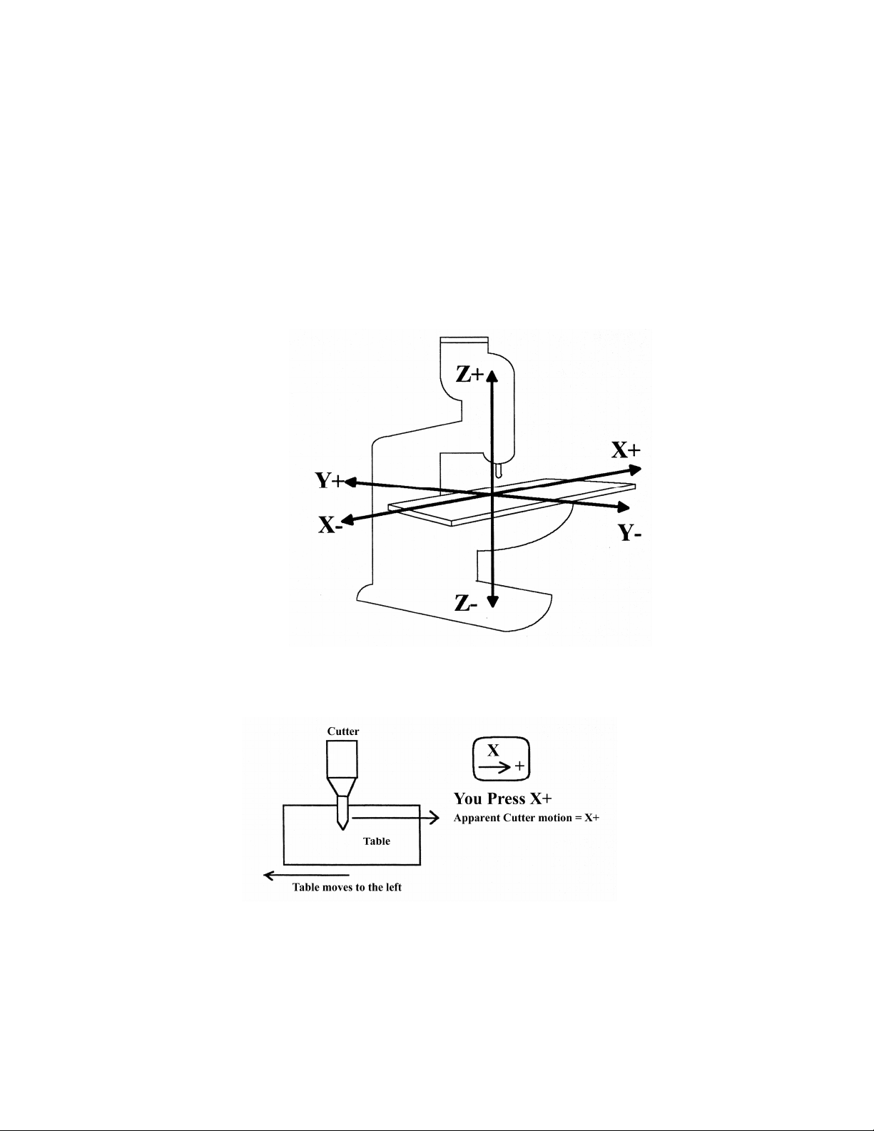
*All program examples and software use the standard Cartesian coordinate system (see the figure below). If you
are facing the mill, the X-axis is defined positive to your right; the Y-axis is defined positive to the mill; and the Zaxis is defined positive upward, perpendicular to the XY plane.
*The direction of motion is defined by the CUTTER motion, not the TABLE motion.
*CW stands for clockwise, and CCW stands for counterclockwise.
M-Series Operator’s Manual 12/20/13 1-3
Page 11
Machine Home
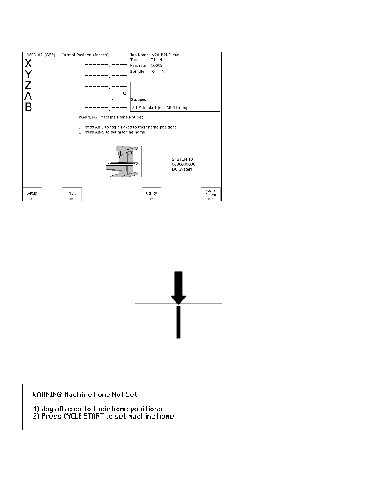
When the M-Series control is first started, the Main screen will appear as below.
Before you can run any jobs, you must set the machine home position. If your machine has home/limit switches,
reference marks or safe hard stops, the control can automatically home itself. If your machine has reference marks,
jog the machine until the reference marks are lined up, (see below), before you press CYCLE START to begin the
automatic homing sequence. The control will execute the G-codes in a file called cncm.hom in the c:\cncm
directory. By default, this file contains commands to home Z in the plus direction, then X in the minus and Y in the
plus direction.
Typical Reference Marks
If your machine does not have home/limit switches or safe hard stops, the following message will appear instead.
In this case you must move the machine to its home position yourself, using either the jog keys or the handwheels.
Once all axes are at their home positions, press CYCLE START to set machine home.
M-Series Operator’s Manual 12/20/13 1-4
Page 12

Mill M and G Codes
This is a summary list of M and G codes. See Chapters 12 – 13 for more information.
M00 Stop for Operator
M01 Optional Stop for Operator
M02 Restart Program
M03 Spindle On Clockwise
M04 Spindle On Counterclockwise
M05 Spindle Stop
M06 Tool Change
M07 Mist Coolant On
M08 Flood Coolant On
M09 Coolant Off
M10 Clamp On
M11 Clamp Off
M25 Move to Z Home
M26 Set Axis Home
M30 Customizable M-code for End of Intercon Program
M39 Air Drill
M91 Move to Minus Home
M92 Move to Plus Home
M93 Release/Restore Motor Power
M94,M95 Output On/Off
M98 Call Subprogram
M99 Return from Macro or Subprogram
M100 Wait for PLC bit (Open, Off, Reset)
M101 Wait for PLC bit (Closed, On, Set)
M102 Restart Program
M103 Programmed Action Timer
M104 Cancel Programmed Action Timer
M105 Move Minus to Switch
M106 Move Plus to Switch
M107 Output BCD (Binary Coded Decimal) Tool Number
M108 Enable Override Controls
M109 Disable Override Controls
M115,M116,M125,M126 Protected Move Probing
M120 Open data file (overwrite existing file)
M121 Open data file (append to existing file)
M122 Record local position(s) in data file
M123 Record value and/or comment in data file
M124 Record machine position(s) in data file
M127 Record Date and Time in a data file
M128 Move Axis by Encoder Counts
M129 Record Current Job file path to data file
M130 Run system command
M200/M201 Stop for Operator, Prompt for Action
M223 Write Formatted String to File
M224 Prompt for Operator Input Using Formatted String
M225 Display Formatted String for A Period of Time
M300 Fast Synchronous I/O update
M1000-M1015 Graphing Color for Feedrate movement
G00 - Rapid to Position
G01 - Linear Move
G02/G03 - CW/CCW Arc Move
G04 - Dwell
G09 - Decel and Stop
G10 - Set Parameter
G17/G18/G19 - XY/ZX/YZ Plane Selection
G20 - Inch Units
G21 - Metric Units
G22 - Work Envelope On
G23 - Work Envelope Off
G28 - Return to Reference Point
G29 - Return from Reference Point
G30 - Return to Secondary Reference Point
G40 - Cancel Cutter Compensation
G41/G42 - Cutter Compensation Left/Right
G43/G44 - Tool Length Compensation +/G49 - Cancel Tool Length Compensation
G50 - Cancel Scaling / Mirroring
G51 - Scaling / Mirroring
G52 - Offset Local Coordinate System Origin
G53 - Rapid Positioning in Machine Coordinates
G54-G59 - Select Work Coordinate System
G61 - Modal Decel and Stop
G64 - Smoothing Mode Selection / Cancel Modal Decel and Stop
G65 - Call Macro
G68 - Rotate
G69 - Cancel Rotate
G73 - High Speed Peck Drilling (Canned Cycle)
G74 - Counter Tapping (Canned Cycle)
G76 - Fine Bore (Canned Cycle)
G80 - Cancel Canned Cycle
G81 - Drilling and Spot Drilling (Canned Cycle)
G82 - Drill with dwell (Canned Cycle)
G83 - Deep hole drilling (Canned Cycle)
G84 - Tapping (Canned Cycle)
G85 - Boring (Canned Cycle)
G89 - Boring with dwell (Canned Cycle)
G90 - Absolute Positioning Mode
G91 - Incremental Positioning Mode
G92 - Set Absolute Position
G93 - Inverse Time Feedrate Mode
G94 - Cancel Inverse Time Feedrate Mode
G98 - Initial Point Return
G99 - R Point Return
G117/G118/G119 - XY/ZX/YZ Plane Selection & Rotation
G173,G174,G176,G181,G182,G183,G184,G185,G189
- Compound Canned Cycles
G180 - Cancel Canned Cycle
M-Series Operator’s Manual 12/20/13 1-5
Page 13

How to unlock software features or unlock your Control
The following are necessary to unlock software features:
1. If you are at the "Demo mode expired" screen, start at step 4.
2. Go to the Main screen of the Control software.
3. Press F7 "Utility" and then F8 "Option"
4. Press F1 "Unlock Option". (You may need to enter the password – usually 137)
5. Next, type in the Unlock # and press ENTER.
6. Then, type in the Unlock Value and press ENTER.
7. Repeat step 4, 5, and 6 for each new Unlock.
M-Series Operator’s Manual 12/20/13 1-6
Page 14
Chapter 2
Operator Panel
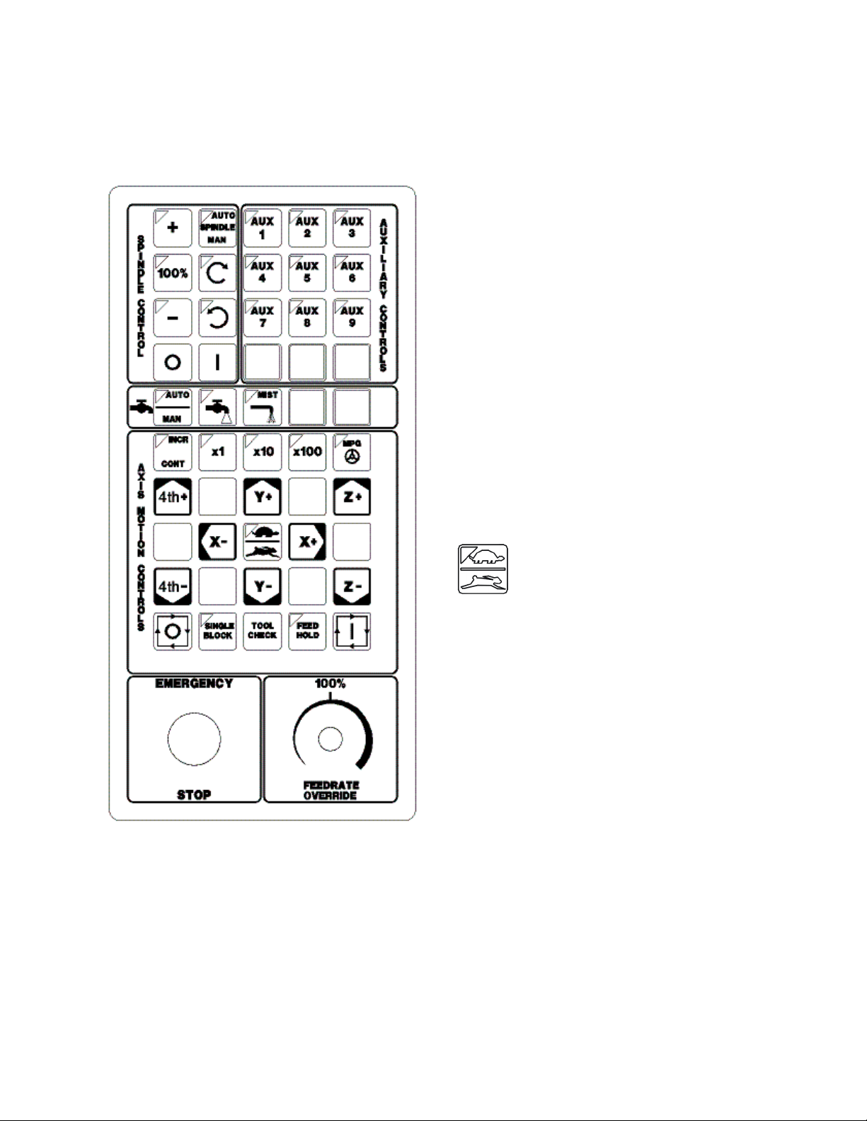
The M-Series operator panel is a sealed membrane keyboard
that enables you to control various machine operations and
functions. The panel contains momentary membrane
switches. The M-Series jog panel can be customized as to
the location of various keys. The jog panel displayed in the
figure above is representative of a default configuration
found on most M-series controls.
Axis Jog Buttons
X+ X- Y+ Y- Z+ Z- 4TH+ 4TH-
The yellow X, Y, Z, and 4TH keys are momentary switches
for jogging each of the four axes of the machine. There are
two buttons for each axis (+/-). Only one axis can be jogged
at a time.
* NOTE: The jog buttons will not operate if the M-Series
CNC software is not running, or if a job (a CNC program) is
running.
Slow/Fast
The slow/fast key is located in the center of the Axis Motion
Controls section and is labeled with the turtle and rabbit
icon shown to the right. The turtle represents slow jogging
mode. When SLOW jog is selected (LED on) and a jog
button is pressed, the axis moves at the slow jog rate. If
FAST jog is selected, the axis will move at the fast jog rate.
See Chapter 14 for information on setting the fast and slow
jog rates for each axis.
Inc/Cont
INC/CONT selects between incremental and continuous
jogging. Pressing the key will toggle between these two
Fig 1 - M-Series Jog Panel
modes. The LED is lit when INC is selected. If CONT jog
is selected and an axis jog button is pressed, the axis will
move continuously until the button is released.
x1, x10, x100
Press any one of these keys to set the jog increment amount. The amount you select is the distance the control will
move an axis if you make an incremental jog (x1=0.0001", x10=0.0010" and x100=0.0100"). You may select only one
jog increment at a time, and the current jog increment is indicated by the key that has a lit LED. The jog increment
you select is for all axes; you cannot set separate jog increments for each axis. The jog increment also selects the
distance the control will move an axis for each click of the MPG handwheel.
M-Series Operator’s Manual 12/20/13 2-1
Page 15
MPG
The MPG is housed in a separate hand-held unit. Press the MPG key to set the control jog to respond to the MPG hand
wheel, if equipped. When selected, the LED will be on. Select the Jog Increment and desired axis and slowly turn the
wheel. When the LED is not lit, the MPG is disabled and the jog panel is on.
Single Block
The SINGLE BLOCK key selects between auto and single block mode. When the SINGLE BLOCK LED is on, the
single block mode has been enabled. Single Block mode allows you to run a program line by line by pressing CYCLE
START after each block. While in block mode you can select auto mode at any time. While in auto mode and a
program is running you cannot select single block mode. Auto mode runs the loaded program after CYCLE START is
pressed. Auto mode is the default (LED off).
Cycle Start
When the CYCLE START button is pressed, the M-400/M-39 Control will immediately begin processing the current
program at the beginning and will prompt you to press the CYCLE START button again to begin execution of the
program. After an M0, M1, M2, or M6 is encountered in the program, the message “Press CYCLE START to
continue” will be displayed on the screen, and the M-400/M-39 Control will wait until you press the CYCLE START
button before continuing program execution.
WARNING
Pressing CYCLE START will cause the M-Series Control to start moving the
axes immediately without further warning. Be certain that you are ready to start
the program when you press this button. Pressing the FEED HOLD button or
the CYCLE CANCEL button will stop any movement if CYCLE START is
pressed accidentally.
Feedrate Override
This knob controls the percentage of the programmed Feedrate that you can use during feedrate cutting moves: lines,
arcs, canned cycles, etc. This percentage can be from 0% to 200%.
CAUTION
The Feerate Override knob will not work during tapping cycles (G74 and G84).
Feed Hold
Feed Hold decelerates motion of the current movement to a stop, pausing the job that is currently running. Pressing
CYCLE START will continue the movement from the stopped location.
CAUTION
FEED HOLD is temporarily disabled during tapping cycles (G74 and G84) and
automatic tool changes (M6).
Tool Check
Press TOOL CHECK while no program is running to move the Z-axis to its home position/G28 position. Press
TOOL CHECK while a program is running to abort the currently running program. The control will stop normal
program movement, pull Z to its home position, clear all M-functions, and automatically display the Resume Job
Screen. From the Resume Job Screen, you can change tool settings (height offsets, diameter offsets, etc.) and resume
the job with the new tool settings.
M-Series Operator’s Manual 12/20/13 2-2
Page 16
Cycle Cancel
Press CYCLE CANCEL to abort the currently running program. The control will stop movement immediately, clear
all M-functions, and return to the Main Screen. It is recommended that you press FEED HOLD first before CYCLE
CANCEL. If you press CYCLE CANCEL, program execution will stop; if you wish to restart the program you must
rerun the entire program or use the search function. See search function operation in Chapter 3 or Chapter 6.
Emergency Stop
EMERGENCY STOP releases the power to all the axes and cancels the current job immediately upon being pressed.
EMERGENCY STOP also resets certain faults if the fault condition has been fixed or cleared.
WARNING
On some machines, vertical axes (such as Z and/or W) may start to move due to
gravity pulling it down when motor power is cut due to EMERGENCY STOP
being pressed.
Spindle CW/CCW
The SPINDLE CLOCKWISE/COUNTERCLOCKWISE keys determine the direction the spindle will turn if it is
started manually. If the spindle is started automatically, the direction keys are ignored and the spindle runs according
to the program. The default direction is CW.
Spindle Speed +
Pressing this key will increase the spindle speed by 10% of the commanded speed in Auto spindle mode, limited by the
maximum speed or 200% of commanded speed, whichever is less. For manual spindle mode, the spindle speed is
increased by 5% of the maximum spindle speed (up to the maximum speed). The LED is on if the spindle speed is set
above the 100% point.
Spindle Speed 100%
Pressing this key will set the spindle speed at the 100% point, which is defined as the commanded speed in Auto
spindle mode, or ½ the maximum spindle speed in manual mode. The LED will be on when the spindle is at the 100%
point.
Spindle Speed -
Pressing this key will decrease the spindle speed by 10% of the commanded speed in Auto spindle mode, limited to
10% of commanded speed. For manual spindle mode, the spindle speed is decreased by 5% of the maximum spindle
speed down to 5% of maximum. The LED is on if the spindle speed is set below the 100% point.
Spindle (Auto/Man)
This key selects whether the spindle will operate under program control (automatic) or under operator control
(manual). When the LED is lit, the spindle is under automatic control. If the LED is off, the spindle is under manual
control. Pressing the SPINDLE (AUTO/MAN) key will toggle it from AUTO to MAN and back again. The default
is AUTO mode.
M-Series Operator’s Manual 12/20/13 2-3
Page 17
Spin Start
Press the SPIN START key when manual spindle mode is selected to cause the spindle to start rotating. Press SPIN
START when automatic mode is selected to restart the spindle if it has been paused with SPIN STOP.
Spin Stop
Press the SPIN STOP key when manual spindle mode is selected to stop the spindle. Press SPIN STOP when
automatic mode is selected to pause spindle rotation and can be restarted with SPIN START.
NOTICE
SPIN STOP should only be pressed during FEED HOLD or when a program is NOT
running.
Coolant Auto/Manual
This key will toggle between automatic and manual control of coolant. In automatic mode, M7 (Mist) and M8 (Flood)
can be used in G-code programs to select the coolant type to be enabled. In manual mode, flood coolant and mist
coolant are controlled by separate keys. Note: When switching from automatic to manual mode, both flood and mist
coolants are turned off automatically.
Coolant Flood
In manual coolant control mode, flood coolant can be toggled off and on by pressing this key. The LED will be on
when flood control is selected in either automatic or manual mode.
Coolant Mist
In manual coolant control mode, mist coolant can be toggled off and on by pressing this key. The LED will be on
when mist control is selected in either automatic or manual mode.
Auxiliary Function Keys (AUX1 – AUX12)
The M-Series jog panel has nine auxiliary keys, some of which may be defined by customized systems.
Notes about operator panels
The behavior of the control system in response to the functions listed above for the M-Series jog panel is dependent
upon optional software options, the PLC program, machine parameters, and hardware wiring of the system. It is
possible that the functioning explained in this chapter does not apply to a particular control system or that it may differ
in some aspects.
M-Series Operator’s Manual 12/20/13 2-4
Page 18
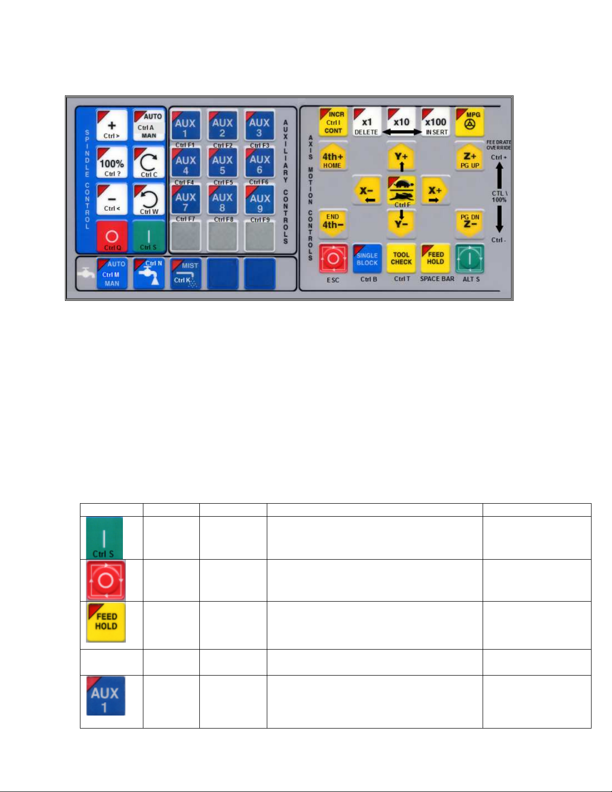
Keyboard Jog Panel
The PC keyboard may be used as a jog panel. Press Alt-J to display and enable the keyboard jog panel. The jog panel
appears as shown below:
Some controls, such as coolant on/off, spindle on/off, feedrate and spindle override will work without the “jog panel”
being displayed but for full functionality (and jogging) of the keyboard jog panel, the “jog panel” must be displayed on
the screen. To enable keyboard jogging, parameter 170 must be set to “1”.
The status window in the upper right corner of the screen displays the jogging mode (continuous/incremental),
incremental step size, and jog speed (fast/slow). In continuous mode, the jog keys start movement when pressed and
movement stops when you release the key. In incremental mode, the axis will move the indicated incremental step
amount.
As shown in the picture above, the jog keys are located in the cursor key block to the right of the main keyboard and to
the left of the numeric keypad. If a jog key controls an axis, it will be overlaid with the axis symbol (“X”, “Y”, etc.)
The jog keys are the arrow keys, Page Up, and Page Down.
The remaining keys are described below:
Legend Key(s) Function Description Availability (Notes)
Ctrl S Cycle Start Same as Cycle Start. Always, with few
Esc Cycle
Space
Cancel
Feed Hold Turns Feed Hold on and off Always, with few
Same as Cycle Cancel. During a job run;
exceptions.
otherwise, Esc is
used to exit menus.
exceptions.
Alt J Start/Exit
Panel
Ctrl F1
Ctrl F12
M-Series Operator’s Manual 12/20/13 2-5
Aux 1 –
Aux 12
Invokes or exits the jog panel. Always, with few
exceptions.
Executes the corresponding Aux function and
signals the PLC. A custom PLC program is
required to act upon jog panel signals.
Always, with few
exceptions.
Page 19
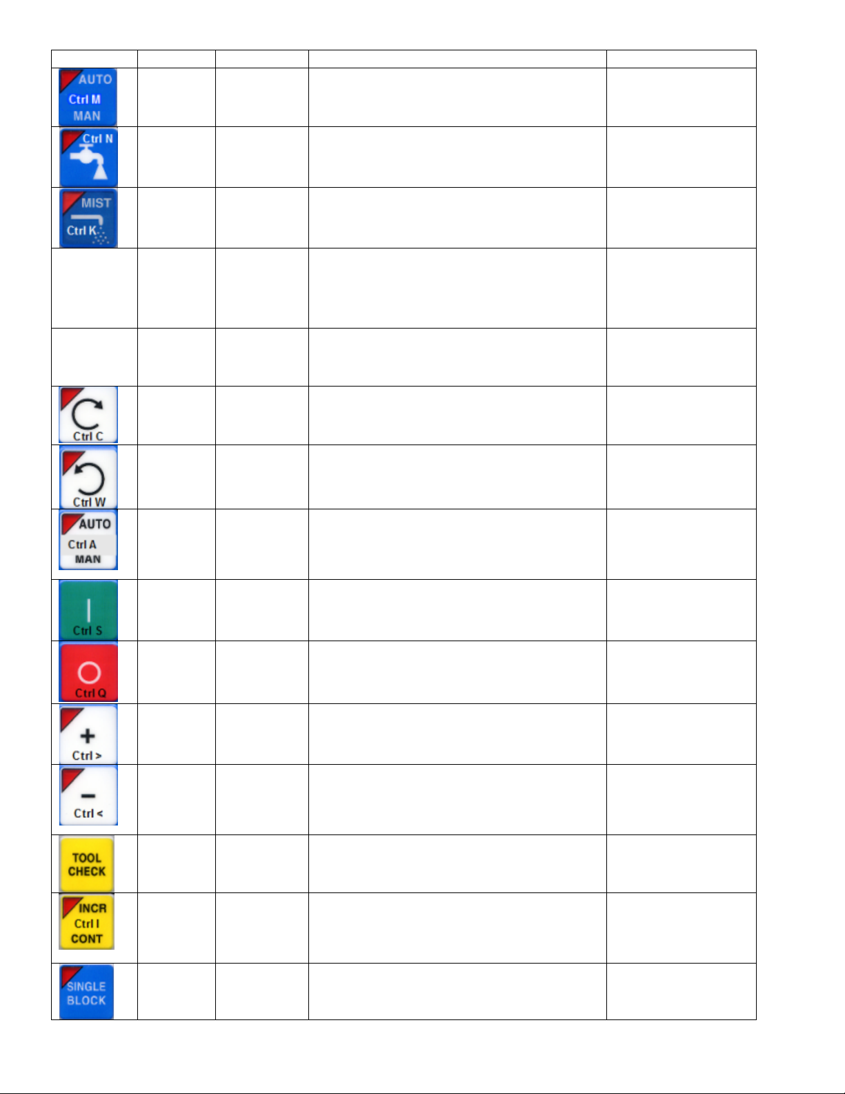
Legend Key(s) Function Description Availability (Notes)
Feedrate
Override
+
Ctrl M Toggle Auto
Coolant
Ctrl N Turns on/off
Flood
Ctrl K Turns on/off
Mist
Ctrl +
Increase
feedrate
override
Toggles coolant mode between auto and
manual.
Toggles Flood coolant if in manual mode Always, with few
Toggles Mist coolant if in manual mode Always, with few
Increase feed rate override by 1% while held. Jog panel, job run,
Always, with few
exceptions.
exceptions.
exceptions.
graphing, and some
other times
Feedrate
Override
-
Ctrl -
Ctrl C Selects CW
Ctrl W Selects CW
Decrease
feedrate
override
Spin
Spin
Decrease feed rate override by 1% while held. Jog panel, job run,
graphing, and some
other times.
Selects CW Spin dir in man mode Always, with few
exceptions.
Selects CCW Spin dir in man mode Always, with few
exceptions.
Ctrl A
Ctrl S Spin Start Starts spindle in selected direction if in
Ctrl Q
Ctrl > Spindle
Ctrl < Spindle
Ctrl T
Ctrl I Incremental/
Ctrl B Selects
M-Series Operator’s Manual 12/20/13 2-6
Toggle
Spindle
Auto/
Manual
Spin Stop STOPS spindle regardless of auto or manual
Override
+1%
Override 1%
Tool Check Performs a tool check.
Continuous
Jog
Selection
Single
Block Mode
Toggles between automatic and manual
spindle operation.
manual mode
mode.
Increase the spindle override by 1% while
held.
Decrease the spindle override by 1% while
held.
Toggles incremental or continuous jog mode. Available most times
Selects single block mode Always, with few
Always, with few
exceptions.
Always, with few
exceptions.
Always, with few
exceptions.
Always, with few
exceptions.
Always, with few
exceptions.
Always, with few
exceptions.
that jogging is
available.
exceptions.
Page 20
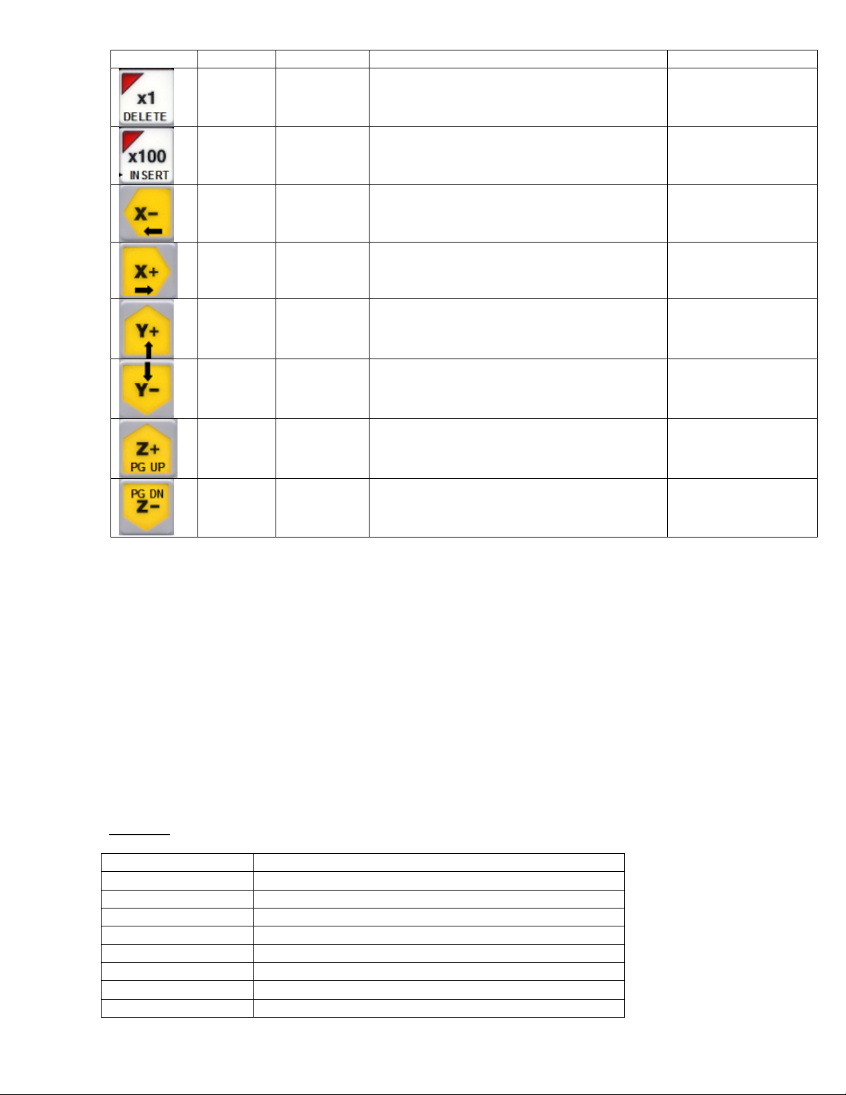
Legend Key(s) Function Description Availability (Notes)
Delete Decrease
Jog
Insert Increase Jog
Left
arrow
Right
Arrow
Up
Arrow
Down
Arrow
Page Up Z + Jog With on screen jog
increment
Increment
X - Jog With on screen jog
X+ Jog With on screen jog
Y+ Jog With on screen jog
Y- Jog With on screen jog
Decreases current jog increment to the next
lower available increment
Increase current jog increment to the next
higher available increment
Always, with few
exceptions.
Always, with few
exceptions.
panel displayed
panel displayed
panel displayed
panel displayed
panel displayed
Page
Down
Z - Jog With on screen jog
panel displayed
MDI and the Keyboard Jog Panel
Many of the keys used by the keyboard jog panel are also possible commands to MDI. To use the keyboard jog panel
functions in MDI, you must press Alt J. You may jog; use the handwheels, or any other jog panel function. Press Alt
J or Esc to return to MDI.
Keyboard Shortcut Keys
A computer style keyboard is supplied with most systems. This keyboard can be used as a jog panel. The keyboard
jog panel has many “hot keys”. Hot keys are keys that can be used at almost any time, with few exceptions. Some
menus may prohibit their use. The CNC software has many other hot keys in addition to the jog panel hot keys. The
hot keys are listed below.
Hot Keys
Hot Key Action
Ctrl A Spindle auto/manual
Ctrl N Flood coolant on/off*
Ctrl M Toggle Auto Man Coolant
ALT D Switch between current position and machine position
CTRL D Switch DRO between position and distance to go
CTRL K Mist coolant on/off*
ALT F Displays available system memory
ALT I PLC diagnostics
M-Series Operator’s Manual 12/20/13 2-7
Page 21
Hot Key Action
ALT J Enables keyboard jogging*
ALT K Displays current ATC tool bin location
ALT M MDI
Ctrl T Tool check*
ALT P Live PID display
CTRL P Clear max and min error display
Ctrl C Spindle CW*
Ctrl W Spindle CCW*
Ctrl S Start Spindle*
Ctrl Q Stop Spindle
ALT S Cycle start
ALT T Displays current motor temperature estimates
ALT V Displays current software version #
ALT W MPG on/off*
ALT + / ALT - Selects next/previous WCS, cycles through WCS 1-18**
ALT 1 - ALT 0 Selects WCS 1 – WCS 10**
ALT Tab Cycle through currently running applications
CTRL F1 - CTRL F12 Executes Aux function 1 – 12*
CTRL V Enables/disables Stall detection in PID Configuration***
CTRL I Creates plcstate.txt when PLC diagnostics is displayed***
CTRL E Starts the PLC Debugger***
Notes: * This is a keyboard jog panel function.
** Not available during jobs or on jog panel.
M-Series Operator’s Manual 12/20/13 2-8
Page 22
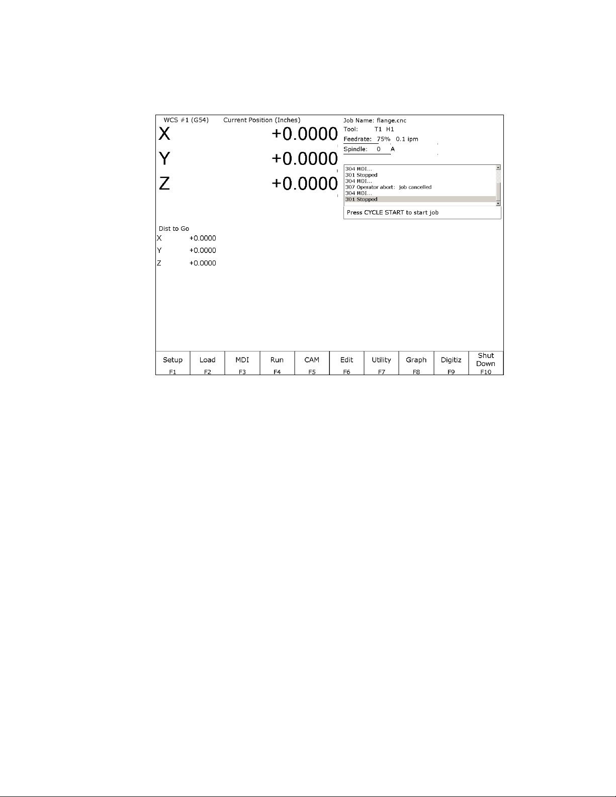
Chapter 3
CNC Software Main Screen
Menu Options:
F1 – Setup Used to set part zeroes, set or change tool offsets, and change the control configuration.
F2 – Load Use this menu to load a job
F3 – MDI The MDI menu allows you to a single line command such as: G1 X2 Y3 F20
F4 – Run Use the Run menu to search and run a job from a specific line, resume a job after it has
been canceled or to change the way a job runs.
F5 – CAM Use the CAM menu to program parts.
F6 – Edit Brings up a G-code (text) editor that allows you to edit the currently loaded job.
F7 – Utility View available software options, backup part and configuration files, create new
directories, and import/export files to and from external locations.
F8 – Graph Graphs the toolpath of the currently loaded part program.
F9 – Digitize Displayed only if the Digitizing option has been purchased. Used to Digitize (reverse
engineer) parts.
F10 – Shut down Power off control. Shutting down your machine without using this menu may damage
your control.
M-Series Operator’s Manual
12/20/13
3-1
Page 23
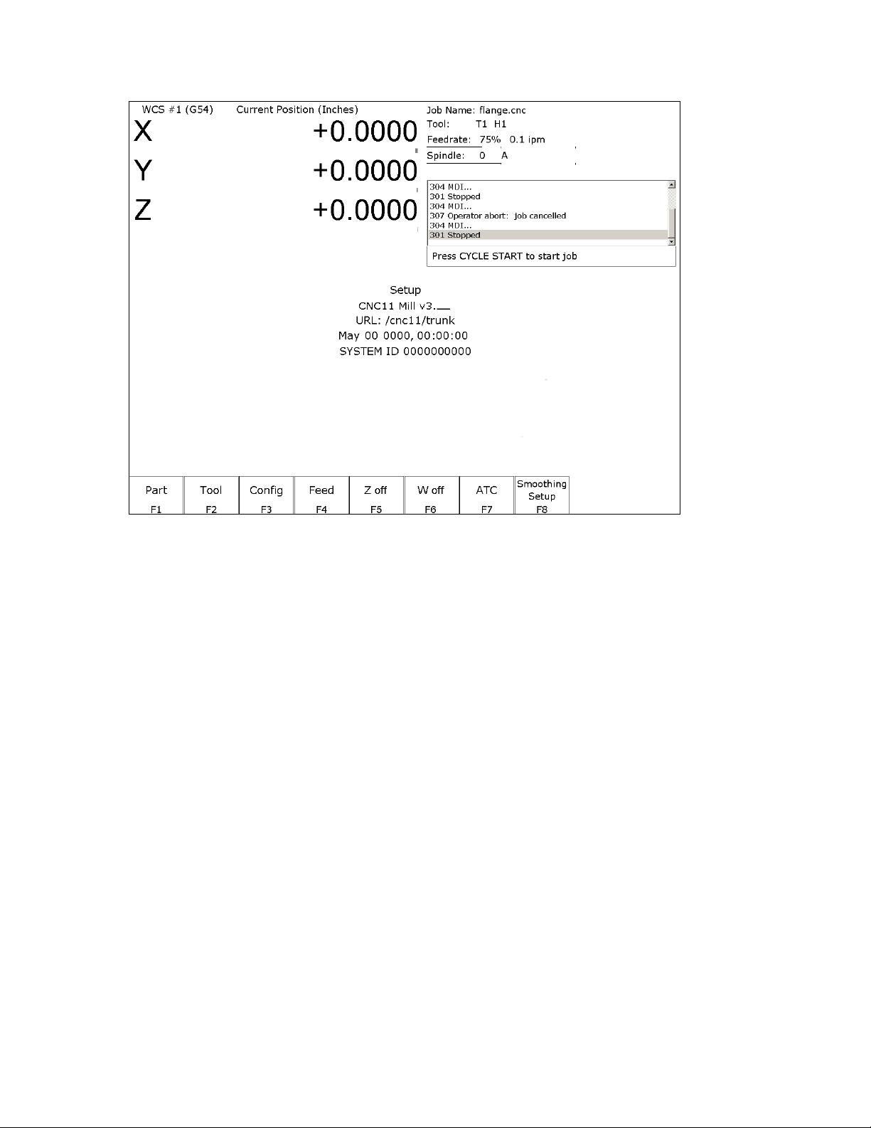
F1- Setup Menu
Setup Menu:
F1 – Part This key displays the Part Setup menus that are explained in Chapter 4.
F2 – Tool This key displays the Tool Setup menus that are explained in Chapter 5.
F3 – Config This key displays the Configuration menu that is explained in Chapter 14.
F4 – Feed This key displays the Feed menu that is discussed in Chapter 6.
F5 – 3rd Axis Toggle This key will only be displayed if machine parameter 130 is set. See Chapter 14
for configuration options.
F6 – 4th Axis Toggle This key will only be displayed if machine parameter 131 is set. See Chapter 14
for configuration options.
F7 – ATC This key will only be displayed if machine parameter 6 is set to 1.0. It has the
same effect as the F7 - ATC key in the Tool menus. It will prompt you for a tool
number and then perform the actions required for an automatic tool change cycle.
F8 – Smoothing Setup This gives you acces to the Smoothing Setup Menu which provides a simplified
way of choosing parameters for the Smoothing module. See Chapter 14 under
“Smoothing Setup Menu”.
M-Series Operator’s Manual
12/20/13
3-2
Page 24
F2- Load Job Menu
Floppy
Floppy Floppy
Floppy
FFFF
2222
Details
DetailsDetails
Details
FFFF
3333
Show
ShowShow
Show
FFFF
4444
Date/
Date/Date/
Date/
FFFF
5555
FFFF
6666
Help
HelpHelp
Help
FFFF
7777
FFFF
9999
F1
F1F1
F1
0000
G code
G code G code
G code
F1
F1F1
F1
Job Name: c:
\
cnc
m\ncfiles
\
bracket.cnc
Use arrow keys to select file to load and press F10 to Accept.
Use arrow keys to select file to load and press F10 to Accept.Use arrow keys to select file to load and press F10 to Accept.
Use arrow keys to select file to load and press F10 to Accept.
////USB/LAN
USB/LAN
USB/LANUSB/LAN
Edit
Edit
On/Off
On/Off
On/OffOn/Off
Recent
Recent
RecentRecent
Alpha
Alpha
AlphaAlpha
EditEdit
On
On////Off
Off
OnOn
OffOff
Graph
Graph
Graph Graph
Advanced
Advanced
AdvancedAdvanced
Accept
Accept
AcceptAccept
arcs.cnc
arcs.cnc
arcs.cncarcs.cnc
bracket.cnc
bracket.cnc
bracket.cncbracket.cnc
flange.cnc
flange.cnc
flange.cncflange.cnc
test fixture plate.cnc
test fixture plate.cnc
test fixture plate.cnctest fixture plate.cnc
Job
Job to
to load? bracket.cnc
load? bracket.cnc
Job Job
toto
load? bracket.cnc load? bracket.cnc
/ICN
/ICN
/ICN/ICN
F1 – G code/ICN Allows the user to change which types of files are displayed.
F2 – Floppy/USB/LAN Select a different drive from which to load files.
F3 – Details Displays file details including: Programmer, Description and Date Modified.
F4 – Show Recent Displays a list of the 15 most recently loaded jobs.
F5 – Date/Alpha Toggles the current view of files to be sorted alphabetically or by date modified.
F6 – Edit Opens selected file in editor.
F7 - Help Displays on screen help for the load screen.
F8 - Graph Backplots (graphs) the selected file.
F9 - Advanced Displays a unified file and device browser similar to Windows Explorer.
Page Up Move the cursor backward one page.
Page Down Move the cursor forward one page.
END Select the last file in the list.
HOME Select the first file in the list.
Arrow Keys
*Note: The path and/or file name may also be selected by typing the path or path and file name. A window
will open automatically when you begin typing.
M-Series Operator’s Manual
12/20/13
3-3
Page 25
F3 –MDI
Pres
PresPres
Pres
s CYCLE START to start job
s CYCLE START to start jobs CYCLE START to start job
s CYCLE START to start job
Repeat
Repeat Repeat
Repeat
F3
F3F3
F3
/Skips
/Skips /Skips
/Skips
Off
Off Off
Off
F
F F
F
4444
RTG
RTG RTG
RTG
Rapid
Rapid Rapid
Rapid
Single Block Mode:
Single Block Mode:Single Block Mode:
Single Block Mode:
Off
OffOff
Off
Run
RunRun
Run
Run
RunRun
Run
----
Time Graphics:
Time Graphics:Time Graphics:
Time Graphics:
Off
OffOff
Off
MDI mode allows you to directly enter M and G-codes one line at time. After entering the M and Gcodes you wish to run, press cycle start to have the controller execute the command. When the command has
finished executing the command, it will prompt you for another line. When you are finished entering
commands, press ESC.
Examples:
Block? G92X0Y0 ; Set the current XY position to 0,0
Block? M92 /Z ; Move the Z to the positive limit.
Block? M26 /Z ; Set the current Z position as Z home
F4 – Run Menu
X +4.0000
X +4.0000
X +4.0000X +4.0000
Y +2.0000
Y +2.0000
Y +2.0000Y +2.0000
ZZZZ
----
Optional Stops:
Optional Stops: Off
Optional Stops:Optional Stops:
Block Skips:
Block Skips: On
Block Skips:Block Skips:
Job Repeat:
Job Repeat: Off
Job Repeat:Job Repeat:
Run job options:
F2 – Search You can resume a job by searching for the line, tool, or a block number.
F3 – Repeat Toggles Job Repeat. Will repeat the current program when a job is finished.
F4 – Block Skips Turns on and off block skips in part programs.
F5 – Single Block Program runs in single block mode when turned on.
F6 – Stops Turns on and off optional stops (M01) in part programs.
F8 – Graph Graphs tool path of currently loaded program
F9 – Rapid Turns on and off rapid override function
F10 – RTG Turns on and off Run Time Graphics
*Note: For more information on these options, please see chapter 6.
Current Position (
Current Position ( Inches
Current Position (Current Position (
Search
Search
Search Search
On
On
On On
Inches )
)
InchesInches
0.5000
0.5000
0.50000.5000
Off
OffOff
On
OnOn
Off
OffOff
) )
Block
Block
BlockBlock
Stops
Stops
Stops Stops
Job Name :
Job Name : bbbbracket.cnc
Job Name : Job Name :
Tool :
Tool : T001 H001
Tool : Tool :
Feedrate : 100%
Feedrate : 100%
Feedrate : 100%Feedrate : 100%
Sp
Spindle : 0 M
indle : 0 M
SpSp
indle : 0 M indle : 0 M
Stopped
Stopped
StoppedStopped
Waiting for PLC operation
Waiting for PLC operation
Waiting for PLC operationWaiting for PLC operation
racket.cnc
racket.cncracket.cnc
T001 H001
T001 H001T001 H001
Graph
Graph
GraphGraph
Off
Off
Off Off
F9
F9
F9 F9
On/Off
On/Off
On/OffOn/Off
M-Series Operator’s Manual
12/20/13
3-4
Page 26
F5 – CAM
ICN
ICNICN
ICN
----
Intercon Mill
Intercon Mill Intercon Mill
Intercon Mill
CAM Selection
CAM SelectionCAM Selection
CAM Selection
Waiting for PLC operation
Waiting for PLC operationWaiting for PLC operation
Waiting for PLC operation
Pres
PresPres
Pres
s CYCLE START t
s CYCLE START ts CYCLE START t
s CYCLE START t
o start job
o start jobo start job
o start job
ICN
ICNICN
ICN
----
Intercon Mill
Intercon Mill Intercon Mill
Intercon Mill
X +4.0000
X +4.0000
X +4.0000X +4.0000
Y +2.0000
Y +2.0000
Y +2.0000Y +2.0000
ZZZZ
----
Current Position (
Current Position ( Inches
Current Position (Current Position (
0.5000
0.5000
0.50000.5000
Inches )
InchesInches
)
) )
Job
Job Name :
Job Job
Tool :
Tool : T001 H001
Tool : Tool :
Feedrate : 100%
Feedrate : 100%
Feedrate : 100%Feedrate : 100%
Spindle : 0 M
Spindle : 0 M
Spindle : 0 M Spindle : 0 M
Stopped
Stopped
StoppedStopped
: bbbbracket.cnc
racket.cnc
: :
racket.cncracket.cnc
T001 H001
T001 H001T001 H001
CAM
CAM Selection
Selection
CAMCAM
Selection Selection
Engrave
Engrave ---- DXF Engraving
EngraveEngrave
Milwrt
Milwrt ---- Millwrite Engraving
Milwrt Milwrt
Manual
Manual
ManualManual
---- Operators Manual
DXF Engraving
DXF Engraving DXF Engraving
Engrave
Engrave
EngraveEngrave
Milwrt
Milwrt
MilwrtMilwrt
Help
Help
HelpHelp
---- DXF Engraving
DXF Engraving
Millwrite Engraving
Millwrite Engraving Millwrite Engraving
Operators Manual
Operators Manual Operators Manual
DXF EngravingDXF Engraving
---- Millwrite Engraving
Millwrite Engraving
Millwrite Engraving Millwrite Engraving
---- Operators Manual
Operators Manual
Operators Manual Operators Manual
ICN
ICN
ICNICN
Engrave
Engrave
EngraveEngrave
Milwrt
Milwrt
MilwrtMilwrt
Manual
Manual
ManualManual
Choose F5-CAM to program parts. The default part programming system is Intercon. Intercon is a
conversational programming system that allows you to quickly and easily create a part program. Intercon
features many easy to use canned cycles for most common machining operations such as: rectangular,
circular and irregular pockets, pockets with islands, bolt hole circles, frames, thread milling operations and
much more. When you are finished programming your part in Intercon, exit to return to the M-Series
Control Main Screen and the posted Intercon program will be automatically loaded and ready to run. For
more information on Intercon, see chapter 10.
F1 – ICN Intercon conversational program system
F2 – Engrave DXF engrave option (optional item part of DXF Import) allows you to import an entire DXF
drawing and engrave it onto a part.
F3 – Milwrite Millwrite Engraving software (optional item) allows you to create engraving files to engrave
letters, numbers, and symbols on your parts.
F4 – Manual Allows you to access the operator manual on the control
M-Series Operator’s Manual
12/20/13
3-5
Page 27
F6 – Edit
This key causes the control to load the current job into a text editor for viewing and/or editing.
When editing, care must be taken to save the file and to quit and exit the text editor before running the file
(the current job). Modifying a file that is currently running as the current job is dangerous and will cause
unexpected results. It is best practice to not edit any files while the machine is moving.
WARNING
Also, note that the C:\CNCM directory contains configuration files and binary data. DO NOT edit these
files. Doing so can cause loss of data and serious malfunctions.
WARNING
Editing a file (modifying and saving) while the machine is moving can cause
personal injury or machine damage.
Do not edit configuration data located in the C:\CNCM directory. Doing so can
cause personal injury or machine damage.
F7 – Utility
From the utility menu you can view available software options, perform diagnostics, backup part and
configuration files, create new directories and import or export files to and from external locations. For
further information please see chapter 7.
F2 – Restore Report Update your control’s configuration with a report.zip file.
F3 – Backup Files Backup your CNC and ICN files
F4 – Restore Files Restore your CNC and ICN files
F5 – File Ops Use this menu to perform file and directory operations.
F6 – User Maint Perform user maintenance.
F7 – Create Report Generates a backup of system configuration files called report.zip.
F8 – Options Shows the software options that you have purchased or added to your control.
F9 – Logs Shows the messages and errors that have been logged by the control.
M-Series Operator’s Manual
12/20/13
3-6
Page 28
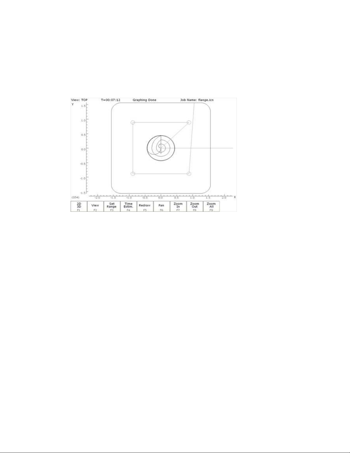
F8 – Graph
This function plots the tool path of the current program loaded. Canned drilling cycles are shown in
gray. Rapid traverse movements are shown in red. Feedrate movements are shown in yellow and cutter
compensated moves are in gray.
F1 - 2D/3D Press this key to view your part isometrically (3D). An axis pointer indicates the current
direction of the view. To return back to the tri-planar view, press F1 again.
F2 – View/Rotate Press this key to change the planar view of your part. The view is indicated by TOP,
RIGHT, or FRONT shown at the top of the screen. In 3D Mode, use this key in 3D
mode to rotate your part, using the keyboard arrow keys to rotate any in direction.
F3 – Range Press this key to set the range of line numbers or block numbers to graph.
F4 – Time Press this key to estimate the time needed to create part. It takes into account
accelerations and decelerations, but neglects tool change times.
F5 – Redraw Press this key to redraw the part at any time.
F6 – Pan Press this key to move the part around the screen. Once pressed, use the crosshairs to
pick a location of the part that will redraw at the center of the screen. Once a section is
selected, press F6 again to continue panning.
F7 - Zoom In Press these keys to zoom into the part relative to the center of the screen.
F8 - Zoom Out Press these keys to zoom away from the part relative to the center of the screen.
F9 - Zoom All Press this key to view the entire part fit inside the screen.
*Note: Use the FEEDRATE OVERRIDE knob to control the speed of the graphing. To pause the tool path,
turn the knob counter-clockwise until it stops. Turn the knob clockwise to resume drawing. On the
offline demo software, the simulated FEEDRATE OVERRIDE knob is controlled by pressing
either Ctrl + or Ctrl –.
M-Series Operator’s Manual
12/20/13
3-7
Page 29
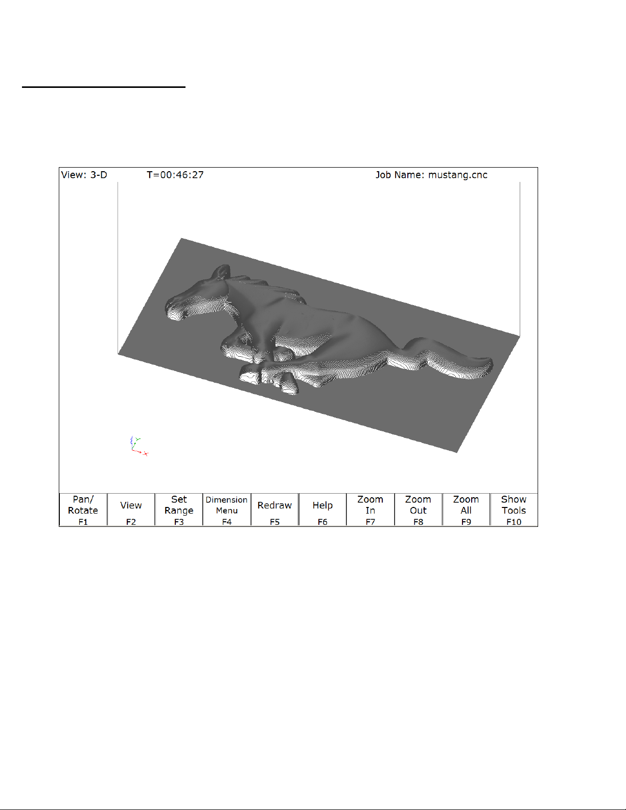
Accelerated Graphics Backplot
Accelerated Graphics Backplot is a new tool path graphics display that takes advantage of the latest
video graphics technology. This option is enabled by setting Parameter 260 to 1 (See Chapter 14). Under
Accelerated Graphics Backplot, the operation of the user interface is slightly different from the regular
Graphing described above.
.
F1 - Pan/Rotate Press this key to change the behavior of the keyboard arrow keys. Normally, they will
pan (scroll) around the drawing, but after pressing this key the arrow keys will control
rotation instead. When in rotation mode, an axis indicator is drawn to mark the center
of rotation.
F2 - View Press this key to change the planar view of your part. The view is indicated by TOP,
RIGHT, or FRONT shown at the top of the screen.
F3 - Set Range Press this key to select which lines of G-code to display. Only lines that fall within
the range you specify will be drawn.
M-Series Operator’s Manual
12/20/13
3-8
Page 30

F4 - Dimension Menu Press this key to access the following sub-menu of options:
F1 – Prev Line: Press this to walk forward to the next G-code line and graphically
highlight it. If this G-code line contains movement, the Start and End points will be
displayed at the bottom of the screen.
F2 – Next Line: Press this to walk backward to the previous G-code line and
graphically highlight it. If this G-code line contains movement, the Start and End
points will be displayed at the bottom of the screen.
F3 – Go To Line: Press this key to graphically highlight a particular G-code line
whose line number you specify. If this G-code line contains movement, the Start and
End points will be displayed.
F4 – Measure: Use this feature to measure between any 2 selected points. To do this,
use a mouse to move the pointer over the first point and then press F4 – Measure to
anchor the first point. Then use the mouse to move the pointer to the second point.
As you move the mouse towards the second point, you will notice an Offset and
Measurement display changing dynamically as you move the mouse. Also you may
notice some “snap to” effects as you move the pointer close to start and end points of
entities that make up your program.
F5 - Redraw Press this key to redraw the part slowly, which can be useful for visualizing the
movements the machine will make. While the display is being redrawn, you can use
the feedrate override knob to adjust the rate at which it is being drawn. If you don't
have a feedrate override knob, the + and - keys can be used to adjust the rate. Pressing
F5 again will cancel this mode.
F6 - Hide Rapids Press this key to hide rapid movements. Press it again to show them.
F7 - Zoom In Press these keys to zoom into the part relative to the center of the screen.
F8 - Zoom Out Press these keys to zoom away from the part relative to the center of the screen.
F9 - Zoom All Press this key to fit the entire part inside the screen.
F10 - Show Tools Press this key to show the tools menu, which allows you to highlight movements of
certain tools. Press this key again to hide the tools menu.
Spacebar - Measure Press this key to take a measurement between two points. In a 2D view, this
measurement will be a 2D measurement. In a 3D view, it will be a 3D measurement
(and the measurement will only be valid if the crosshairs are snapped to a line of the
tool path).
*Note: If you have a mouse or touch screen attached to your device, you can use that to control the
graphing window. Holding the left mouse button allows you to drag the part across the screen, while the
right mouse button controls rotation of the part. Spinning the mouse wheel (or holding both left and right
buttons) zooms in and out. Double clicking on a feedrate movement will center the camera on that
movement (which is very useful) and also tells you the length of that movement. For touchscreen operation,
use the F1 key to switch between Pan and Rotate modes.
M-Series Operator’s Manual
12/20/13
3-9
Page 31

F9 – Digitize
Use this to bring up the Digitize screen. This screen allows you to set up and run touch probe
digitizing. See Chapter 8 for a detailed description of the digitizing operation.
F10 – Shutdown
Use to enter the Shutdown menu. This menu allows you to park the machine, power off the control,
start a command window or exit CNC software.
F1 – Park Use this to park the machine at the end of the day for quicker machine homing at
startup. Once F10- Park is selected, The CYCLE START key must be press to start
machine movement. The park feature homes each axis, at the maximum rate, to ¼ of
a motor revolution from its home position.
F2 – Poweroff Use this to properly shutdown the control. With most controls, this action turns off
the control once the system has prepared itself to be shutdown. Just like a desktop
computer, the control should be properly shutdown before turning off the power in
order to reduce the risk of corrupting data on the hard drive. This will only turn off
the control. The machine itself will still need to be manually turned off.
F6 – System Prompt This brings up the command line interface. Type the command exit to exit the
command window.
F9 – Exit CNC11 Use this to exit the CNC control software.
M-Series Operator’s Manual
12/20/13
3-10
Page 32
Chapter 4
Part Setup
(F1 from Setup)
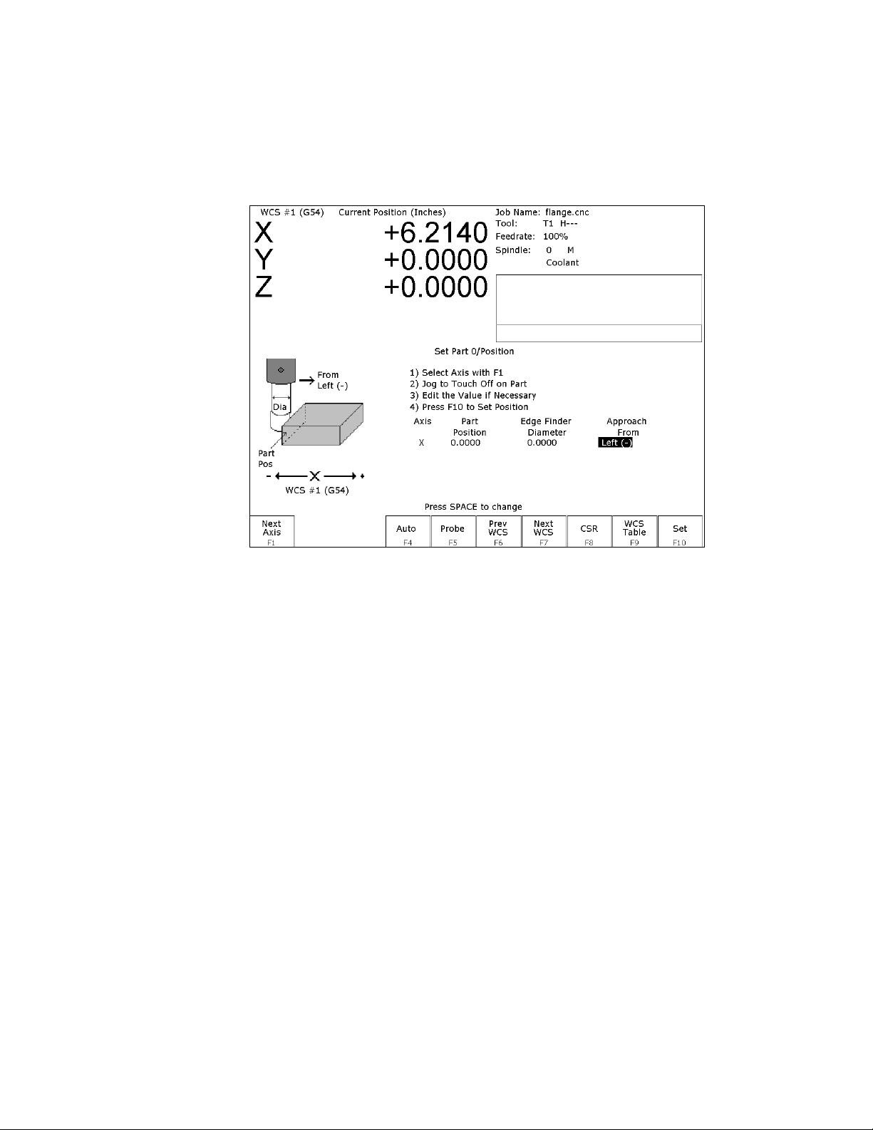
The Part Setup menu is used to set the part position or the coordinate system origin for the part.
F1 – Next Axis Will toggle to the next axis. If changes were made to the current axis, but not yet accepted, they
will be discarded.
F4 – Auto Uses probe to automatically measure and set part position. Make sure your probe height and diameter
offsets are set for the tool number you assigned to the probe and that parameter 12 is set to that tool
number. See Chapter 9 for more details.
F5 – Probe Will open the probing operations menu. See Chapter 9 for details.
F6 – Prev WCS Will select the previous work coordinate. The position being set will only affect the currently
selected work coordinate.
F7 – Next WCS: will select the next work coordinate. The position being set will only affect the currently selected
work coordinate.
F8 – CSR Will open the CSR menu, which can be used to automatically detect coordinate system rotation. This
function key appears only when the software option for Coordinate System Rotation is unlocked.
F9 – WCS Table Will open the Work Coordinate System (WCS) Configuration screen. See the Work Coordinate
System Configuration section later in this chapter for a complete description.
F10 – Set Will accept the position for the current axis, correcting for edge finder diameter based on the approach
direction if appropriate. It will not automatically advance to the next axis.
M-Series Operator’s Manual 12/20/13 4-1
Page 33
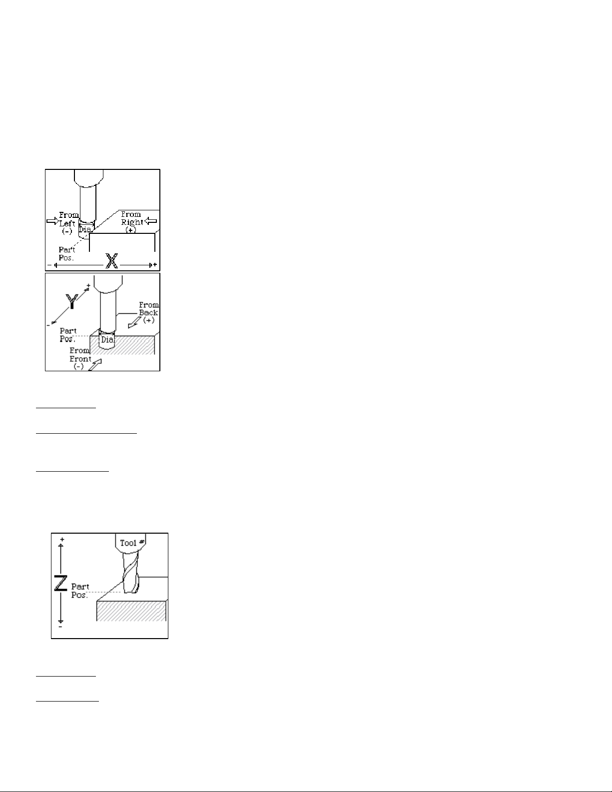
Operation Description
Z 0.0000
0
Setting the part position establishes a coordinate system with an origin at the part zero.
The F1 - Next Axis option selects the axis to be defined next. This field toggles between axis X, Y, Z, 4th, and 5th
Axes. For each axis you will see a graphic description of the parameters to be entered, as well as the corresponding
fields.
Setting up X or Y AXIS
Set Part Position
1) Select Axis with F1
2) Jog to Touch Off on Part
3) Edit the Value if Necessary
4) Press F10 to Set Position
Axis Part Edge Finder Approach
Position Diameter from
X 0.0000 0.0000 Left (-)
Part Position: enter the value of your part zero position or the offset.
Edge Finder Diameter: enter the diameter of the tool, or edge finder you are using to determine the part zero. The
value entered is stored.
Approach From: Toggle the direction the edge finder or probe is approaching the part.
*Note – Use the arrow keys to toggle between Part Position, Edge Finder Diameter, and Approach From options.
Setting up the Z AXIS
Set Part Position
1) Select Axis with F1
2) Jog to Touch Off on Part
3) Edit the Value if Necessary
4) Press F10 to Set Position
Axis Part Tool
Position Number
Part Position: enter the value of your part zero position or the offset.
Tool Number: enter the tool number from the Tool Library that corresponds to the tool being used. When the Tool
Number field is set to a value other than zero, the controller uses the Height Offset for that tool from the Tool
Library to calculate the actual position.
M-Series Operator’s Manual 12/20/13 4-2
Page 34
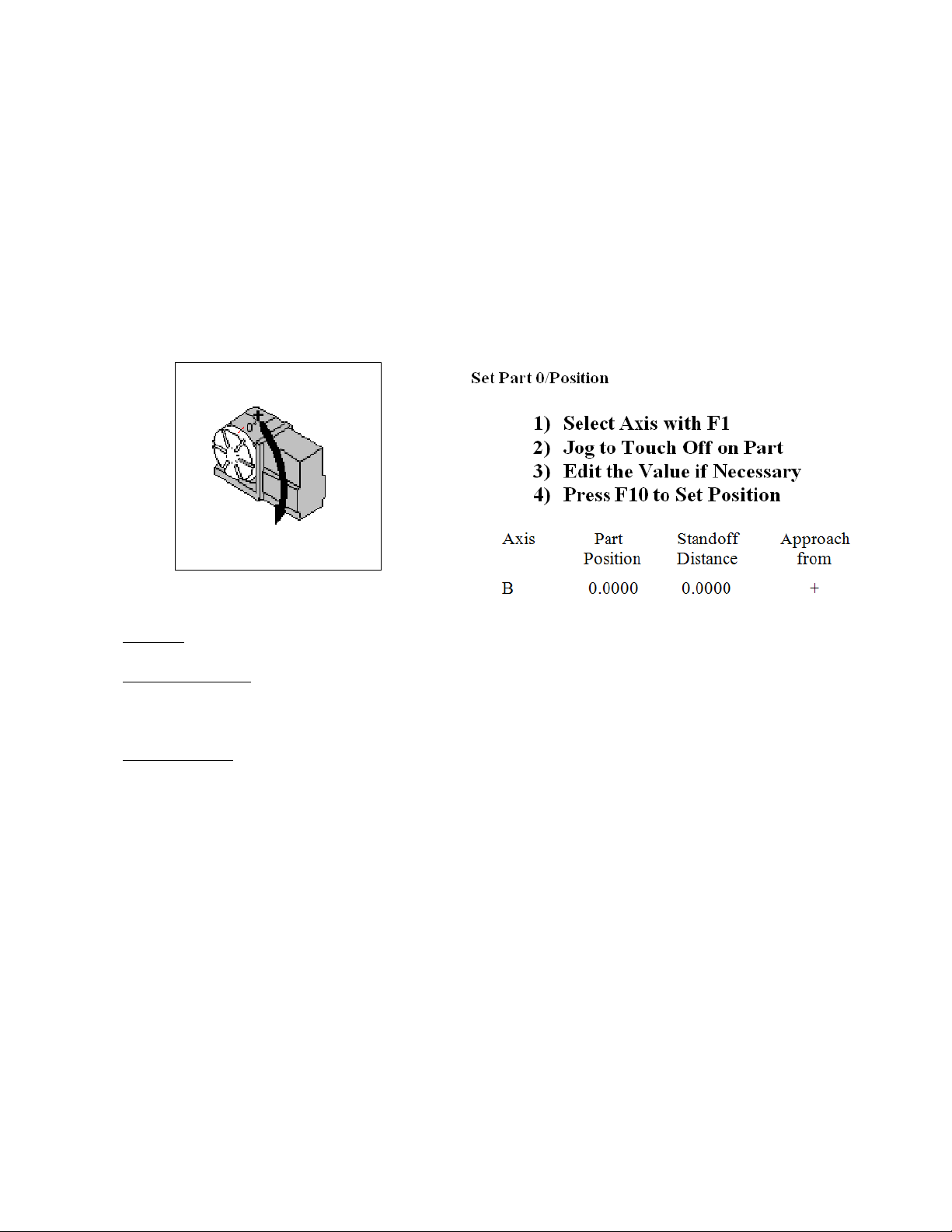
Example 1 (You are using the reference tool to find the Z-axis part zero):
Set Tool Number to 0: setting the Tool Number to zero tells the controller that you are using the reference tool.
Example 2 (You are using a tool other than the reference tool, and not a ball nose cutter):
Set Tool Number to a number tool that is assigned in the tool library (make sure its height offset is set).
Example 3 (You are using a ball nose cutter, other than the reference tool):
Set Part Position to the position of the surface plus the nose radius of the ball nose cutter, set Tool Number to the
number this tool is assigned in the tool library.
The Tool and Offset libraries must be up to date before setting the Z-axis Part Zero.
Setting up the 4th or 5th AXIS***
Position: enter the value of your part zero position or the offset.
Standoff Distance: this field is a generic parameter. Its physical meaning will depend on the specific nature of your
machine's fourth axis. It is the distance between the center of the tool and the point at which the tool is touching the
part surface.
Approach from: enter the direction the edge finder is approaching the part from. Enter the correct direction given
the nature of your 4th-Axis.
Using Multiple Work Coordinate Systems
If you will be using multiple work coordinates, you must set the part position separately for each work coordinate.
Follow the instructions above to set the position for each axis in the first coordinate system. Then move to the next
fixture and press F6 – Prev WCS to select the previous work coordinate or F7 – Next WCS to select the next work
coordinate. The currently selected coordinate system is displayed below the axis picture on the Part Setup screen.
It is also displayed above the DRO at all times. For a description on setting up each work coordinate, see the Work
Coordinate System Configuration section later in this chapter.
NOTICE
This procedure does NOT apply to tilt table setup.
M-Series Operator’s Manual 12/20/13 4-3
Page 35
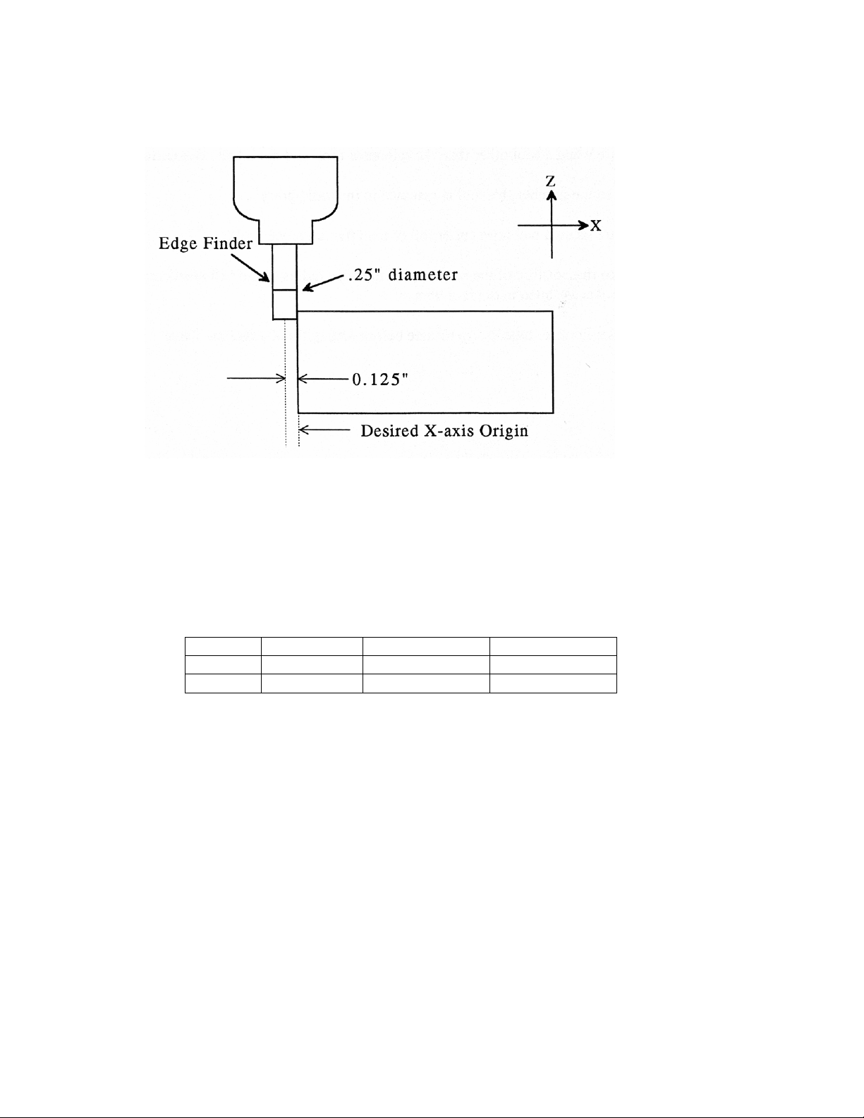
Part Setup Examples
Example 1: Setting the X-axis Part Zero with no offset (See diagram below)
If you wanted the left edge of the part to be the origin for the X-axis:
1. Move the Edge Finder to the left edge of the part
2. Press F1 – Next Axis until the Axis label displays 'X'
3. Move the cursor to the Edge Finder Diameter field
4. Type .25 and press ENTER
5. Press SPACE until Left (-) is displayed
6. Press F10 - Set to accept the values
Axis Part Edge Finder Approach
Position Diameter From
X 0 0.25 Left (-)
Since no offset is being applied, Position is zero. The Edge Finder is approaching the part from the -X direction
and has a diameter of .25 inches. Once this data is entered and F10 - Set is pressed, the X-axis DRO display will
read -0.125. This means the center of the Edge Finder is sitting to the left (minus) of the part by 0.125 inches (half
of the Edge Finder Diameter).
This value is computed by: Position (Approach from) Edge Finder Diameter / 2.
Where (Approach from) is the sign of the approach direction. In other words, if the approach direction is minus,
then the value is: Position - Edge Finder Diameter / 2 = 0.0 - .25 / 2 = -0.125
M-Series Operator’s Manual 12/20/13 4-4
Page 36
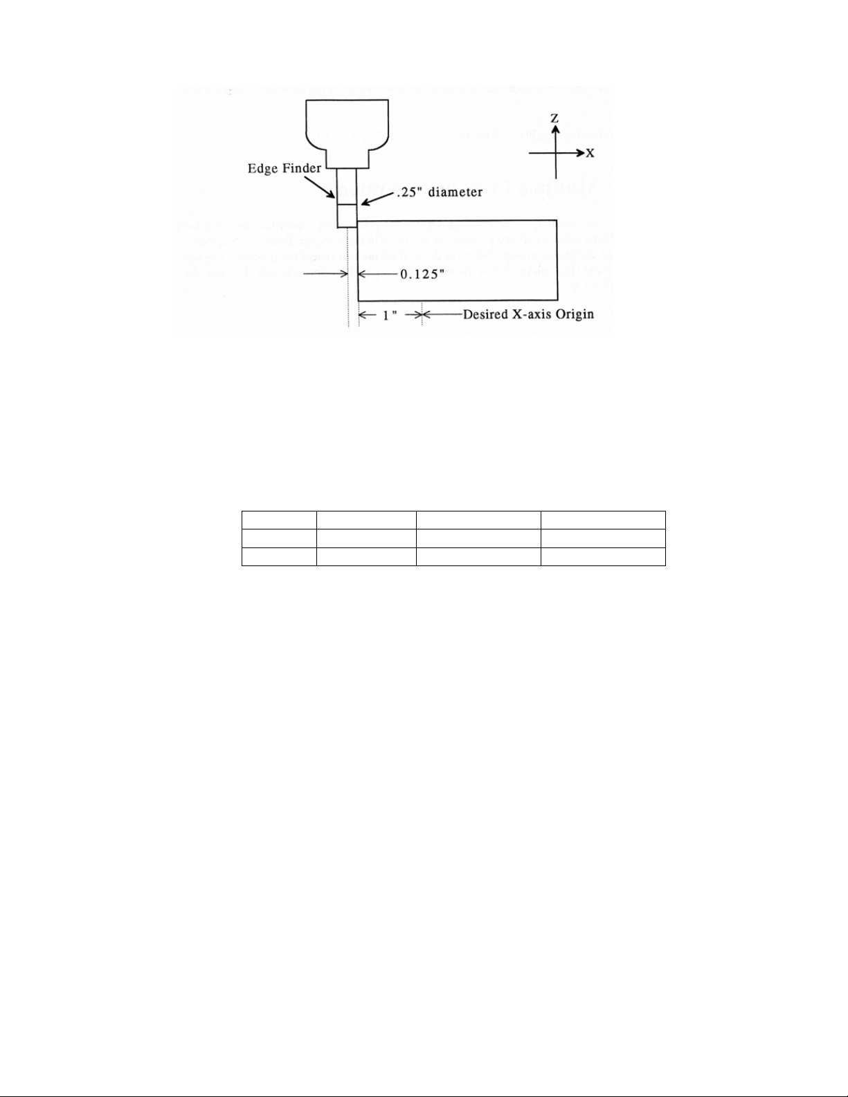
Example 2: X-Axis origin offset into part 1 inch.
If you wanted the origin offset 1 inch into the part:
1. Move the Edge Finder to the left edge of the part
2. Press F1 – Next Axis until the axis field displays 'X'
3. Move the cursor to the Part Position field
4. Type -1 and press ENTER
5. Type .25 and press ENTER
6. Press SPACE until Left (-) is displayed
7. Press F10 - Set to accept the value
Axis Part Edge Finder Approach
Position Diameter from
X -1 0.25 Left (-)
The Position value is relative to the current position of the Edge Finder. Part position equals -1.0 since the Edge
Finder is positioned 1 inch to the left (minus direction) of where you want the X-axis origin.
Another way to view the Part Position value is to assume the origin is already set at 1 inch into the part. In this
case, the Edge Finder would have to move -1 inches from where the origin is to get to the left edge of the part.
The Edge Finder is approaching the part from the -X direction and has a diameter of .25 inches. Once this data is
entered and F10 - Set is pressed, the X-axis DRO display will read -1.125. This means the center of the Edge
Finder is sitting to the left (minus) of the origin by 1.125 inches. The X-axis origin is now 1 inch into the part.
This value is computed by: Position (Approach from) Edge Finder Diameter / 2.
Where (Approach from) is the sign of the approach direction. In other words, if the approach direction is minus,
then the value is:
Position - Edge Finder Diameter / 2 = -1.0 - .25 / 2 = -1.125
M-Series Operator’s Manual 12/20/13 4-5
Page 37
Work Coordinate Systems (WCS) Configuration
Press F9 – WCS Table from the Part Setup screen to display the Work Coordinates System (WCS) menu. The
Work Coordinate Systems screen provides access to reference return points, coordinate system origins, and work
envelope. Make sure your Home position has been set properly. Otherwise, the positions of each coordinate
system will not be in the appropriate position.
When you enter the Work Coordinate System Configuration screen, the DRO display will automatically switch
over to machine coordinates as an aid to entering numbers. All the values on this screen are represented in machine
coordinates.
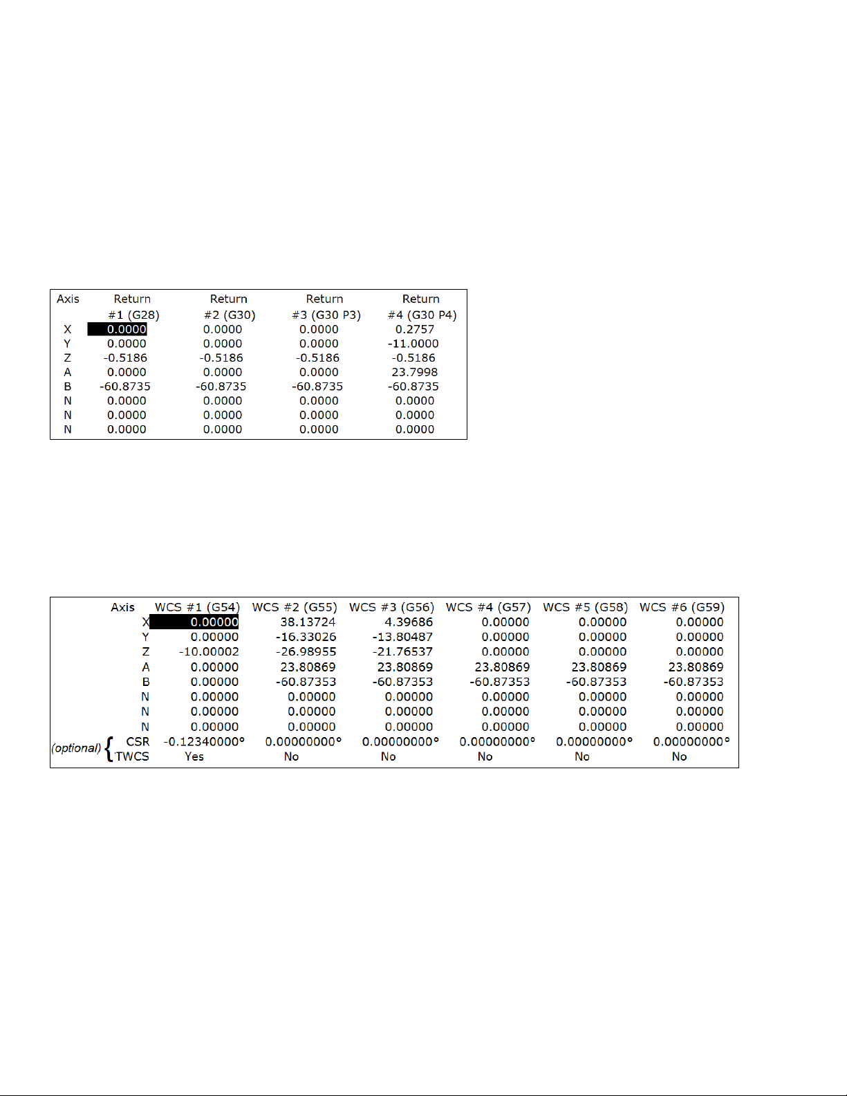
F1 - Reference Return Points Press this key access the menu that sets the reference return points for the
machine.
The reference return points are used with the G28 and G30 codes (see Chapter 12). They are specified in machine
coordinates. The Z coordinate of the first reference point is also used as a Z home position by the M2, M6, and
M25 codes (see Chapter 13).
F2 – Origin Use this key to access the menu for specifying the locations (in machine coordinates) of the origins
for all 18 work coordinate systems. Pressing F1 – Next Table will allow you to view the other WCS (6
per page). This menu is a convenience and is not an absolute necessity for setting work coordinate system
origins nor the CSR angles.
All coordinate systems are relative to Home position that is set during control power up. Note that while in this
screen, the DRO shows the actual machine position relative to Home, not the location relative to the WCS origin.
If the software option Coordinate System Rotation is unlocked, the CSR angle for each of the coordinate systems
can also be set. (This is an optional feature.)
For machines configured as an Articulated Head system with the TWCS feature enabled (set via Paramter 166), the
TWCS=Yes/No differentiates which WCS’s are transformed or not. See Transformed WCS later in this chapter.
M-Series Operator’s Manual 12/20/13 4-6
Page 38
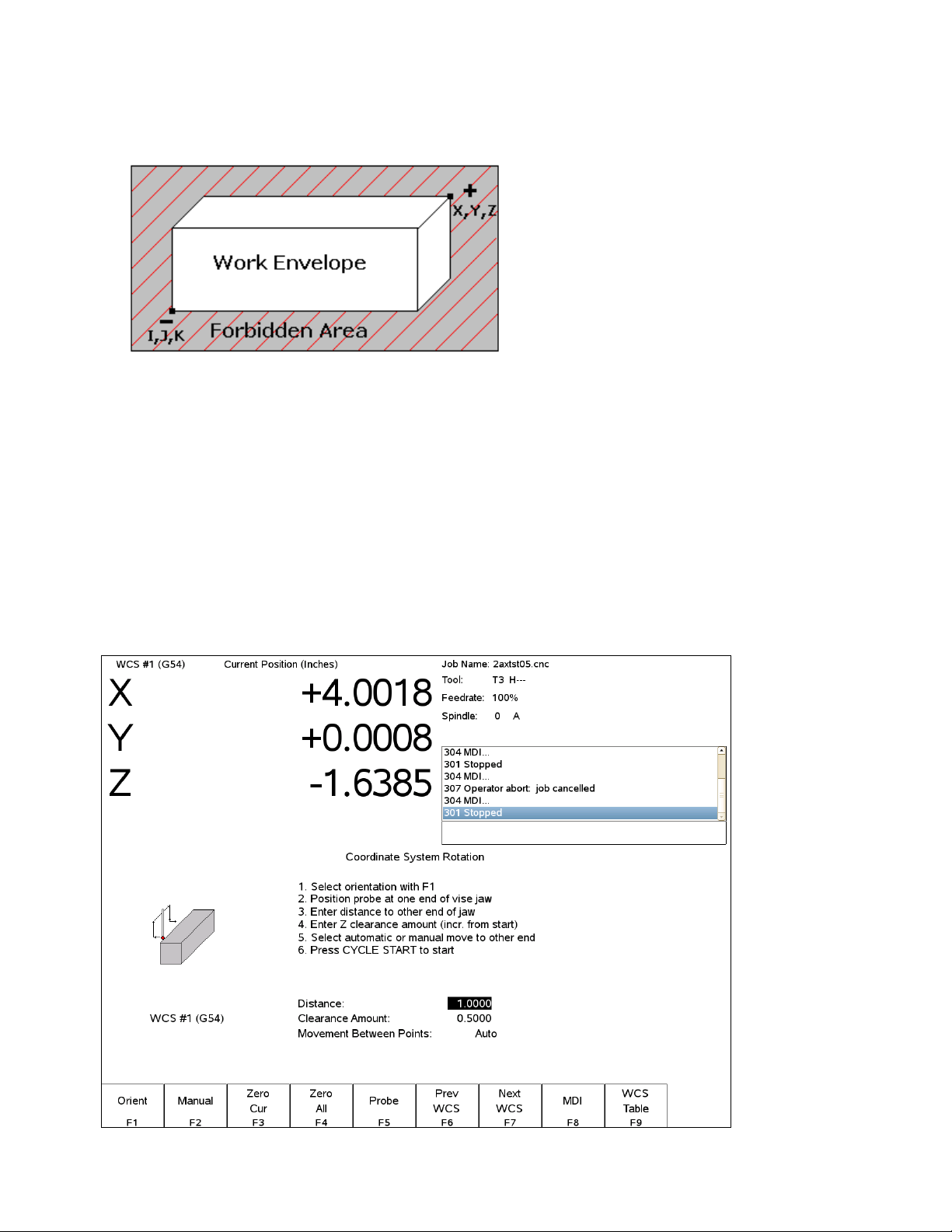
F3 – Work Envelope Use the F3 – Work Envel key to specify the ‘+’ and ‘-‘work envelope locations (in
machine coordinates) used in conjunction with the G22 G code. The X, Y, Z and I, J, K parameters
specified in the G22 G code are stored here, so subsequent G22 codes do not need to specify the limits
unless they change.
Note: The work envelope will only work in programmed moves. You will still be able to jog outside the work
envelope.
Coordinate System Rotation (CSR)
Coordinate System Rotation saves you time when setting up your part. Rather than clamping your part and
indicating the edge of the material to square it with the machine axes, you can use CSR to automatically rotate the
coordinate system to the angle of the part or fixture that was probed. This allows you to compensate for different
orientations.
Simply clamp your part, and then probe two points along either the X or Y-axis of the material using the process
described below.
M-Series Operator’s Manual 12/20/13 4-7
Page 39
F1 - Orient is used to select the orientation for the CSR measurement. There are four possible orientations, which
are: from the front (pictured above), the back, and the left and right sides.
F2 - Manual is used to determine the CSR angle without probing. The user jogs an edge finder to two positions
along one wall. These positions will be used for computing the CSR angle.
F3 - Zero Cur is used to set the CSR angle for the current WCS to zero.
F4 - Zero All is used to set all CSR angles to zero.
F5 – Probe Will open the probing operations menu. See Chapter 9 for details.
F6 - Prev WCS and F7 - Next WCS are used to cycle through the available WCS systems.
F8 – MDI The MDI menu allows you to a single line command such as: G1 X2 Y3 F20
F9 - WCS Table is a shortcut to the Work Coordinate System Configuration Screen described above.
The instructions on how to perform a CSR measurement are numbered on the screen.
Distance: The distance the X-axis (in front or back orientation) or Y-axis (in right or left side orientation) will
move to probe the second point. If the distance is negative, the axis will be moved in the negative direction.
Clearance Amount: The distance the Z-axis will be moved upward when moving between the first probe point and
the second probe point. The clearance move will only be made when using the “Auto” option of the Movement
between Points.
Movement between Points can be toggled between Jog and Auto modes. In Auto mode, the clearing moves are
made automatically as well as the move to the second point. In Jog mode, a prompt will be displayed in the center
of the screen after the first point is probed.
Transformed WCS (TWCS=Yes)
This section only applies to Articulated Head machines with the TWCS feature enabled via Parameter 166 (see
Chapter 14 for more information on setting Parameter 166). On such a machine, when a WCS has a setting of
TWCS=Yes, this is then called a transformed WCS (abbreviated as TWCS).
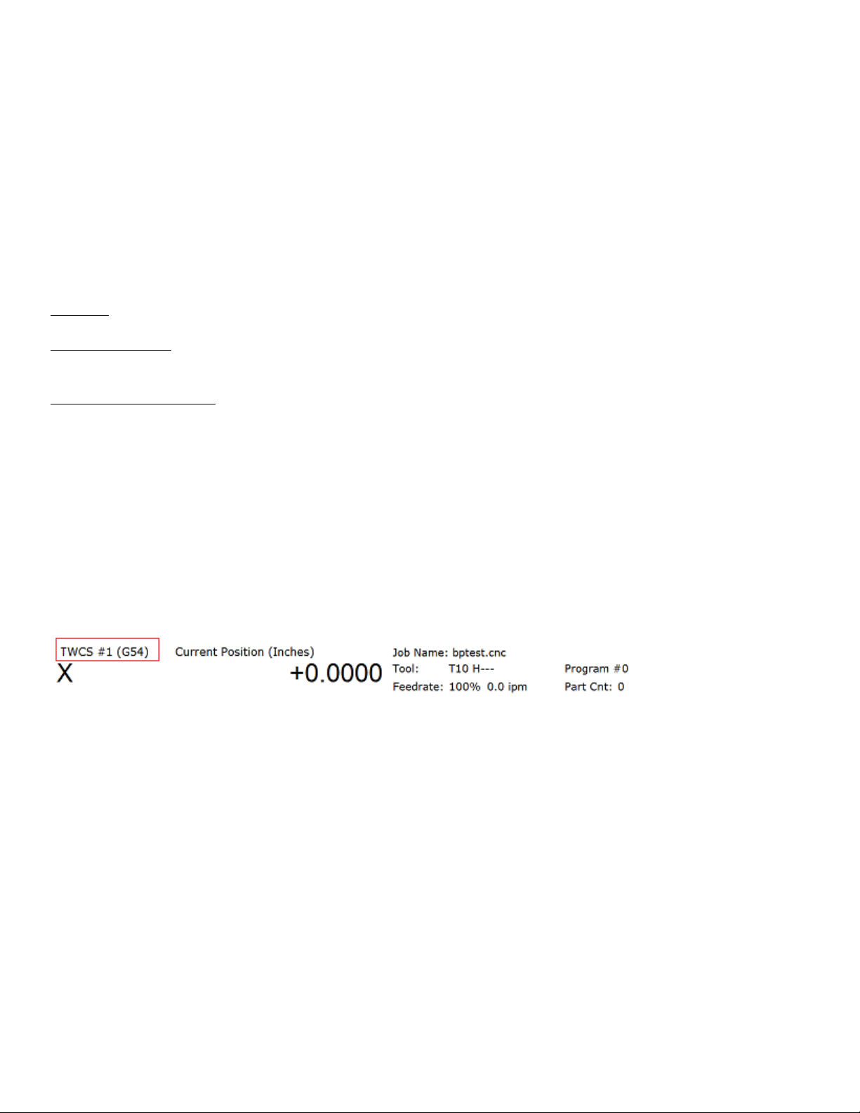
When a TWCS is selected, the DRO will show axis positions based on the TWCS’s frame of reference. In other
words, the shown positions are transformed based on the position of the B axis (5th axis). Furthermore, the WCS
label will be shown as “TWCS” to indicate that the currently selected WCS is indeed transformed.
Also, when the Probing Cycles are run with a TWCS selected, the results shown will be based on the TWCS frame
of reference.
Ordinary 3 axis moves types performed while running a CNC program with a TWCS selected will be automatically
transformed. Such move types include:
• G0, G1, G2, G3
• Protected move probing functions M115, M116, M125, M126
• Canned Cycles G73, G74, G76, G81, G82, G83, G84, G85, G89
• M25
• Moves that involve CSR and Cutter Compensation
However, moves that will not be transformed are:
• Homing moves M91/M92
• Move to switch M105/M106
• Move axis by counts M128
M-Series Operator’s Manual 12/20/13 4-8
Page 40
Chapter 5
Tool Setup
(from Main Screen: F1 Setup ► F2 Tool)
Tool Setup allows you to specify information about the tools you will be using.
Press F1 - Offset Library, to edit the Height Offset and Diameter (H and D) values, or
Press F2 - Tool Library to edit the tool descriptions., or
Press F3 - Tool Life to edit the Tool Life Management settings.
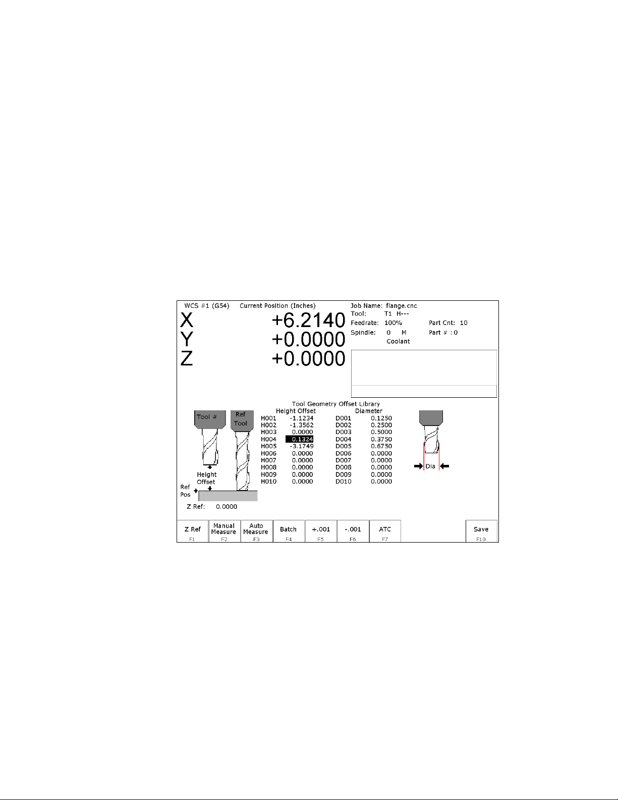
Offset Library
(from Main Screen: F1 Setup ► F2 Tool ► F1 Offset Lib)
The Offset Library file contains the values for the Height Offset and Diameter Numbers. For example, if entry
H01 has a value of -.25, a height offset of -.25 is applied when height offset 01 is referenced. If entry D01 shows a
value of 1.5, the diameter offset 01 has a diameter of 1.5 associated with it.
Press F1 – Z Ref to set the Z reference height. Press F2 - Manual to manually measure tools. If you purchased the
Automatic Tool Measurement (TT1) option, press F3 - Auto to automatically measure tool lengths. Press F5 -
+.001 or F6 - -.001 to adjust the selected offset. If you have an automatic tool changer installed, press F7 - ATC to
change tools. Press F10 - Save to save changes and exit, or ESC to exit without saving changes. If you have both
purchased the Automatic Tool Measurement (TT1) option and also have an automatic tool changer installed, then
you can press F4 - Auto to perform batch tool measuring, by entering a list of multiple tool numbers.
You can inspect and change any of the 200 Height Offset (H) values, and any of the 200 Diameter (D) values. In
most cases you will use the automatic tool length measurement features described below to set H values, and you
will enter D values manually, based on the known or measured diameters of your tools.
Note that H01 and D01, H02 and D02, H03 and D03, etc. are displayed together on the same line for convenience
only. The Height and Diameter Offset Numbers can be used independently; associations are made only in the Tool
Library.
M-Series Operator’s Manual 12/20/13
5-1
Page 41

Height Offset
This is the distance the control adjusts Z-axis positions when tool length compensation (G43 or G44) is used with a
particular H value. For example, if H001 is -1.0 and the job contains G43 H1, then the CNC software will shift all
Z-axis positions down 1.0 to compensate for the shorter tool.
To edit the Height Offset entries move to the desired height offset number with the arrow keys, Page Up, Page
Down, HOME, and END. You can choose to manually edit or automatically measure the value.
Height Offsets values are measured using the Z Reference position. The Z Reference position is the Z-axis position
when the tip of the reference tool is touching the work surface. The reference tool should always be the longest
tool.
The Height Offset value for end mills and drills is the difference between the Z-axis position when the tip of the
tool is touching the work surface and the Z Reference position. The Height offset value for ball nose and bull nose
cutters is the difference between the Z-axis position when the center of the tool is at the work surface and the Z
reference position. Because it is not possible to position the tool in this way, you must instead move the tip of the
tool to the work surface, and then manually edit the value to subtract the tool nose radius.
To manually edit a Height Offset value, simply type the desired value and press ENTER.
To manually measure Height Offset values, use the following procedure:
Establishing the Z reference position
Press F1 – Z Ref to select the Z Reference setting function.
Insert the longest tool into the tool holder (you can use the jog keys or the TOOL CHECK key to assist you).
Jog the tip of the tool down to the top of the work surface.
Press F10 - Save to save this Z Position as the Reference Position.
Measuring each tool height (Z position for tool minus Z position for Reference tool)
Insert the desired tool into the tool holder (Jog keys or the TOOL CHECK key can be used to assist you).
Jog the tip of the tool down to the top of the work surface.
If the tool is a drill or end mill, press F2 –Manual Measure to measure the height.
If the tool is a ball nose or bull nose cutter, press F2 – Manual Measure to measure the height, and then subtract
the tool nose radius.
After a tool height is measured, the next Height Offset entry is automatically selected.
When the edit is complete, press F10 - Save to save the Offset Library and Exit.
Examples (assuming Z Reference = -1.5):
If the tool position is -1.75, then the tool height = -0.25
If the tool position is -1.75 and nose radius is .25, then the tool height = -0.50
If the tool position is -2.25, then the tool height = -0.75
If the tool position is -2.75 and nose radius is .125, then the tool height = -1.375
Diameter
This field tells the control the distance to adjust when cutter diameter compensation (G41 or G42) is used with a
particular D value. For example, if D001 is 0.5 and the job contains G41 D1, the CNC software will adjust all X-Y
positions 0.25 (half the tool diameter) to the left of the programmed tool path.
To edit the Diameter entries move to the desired diameter offset number with the arrow keys, Page Up,
Page Down, HOME, and END. You must manually edit the Diameter Offset value. Type the desired value and
then press the ENTER key.
You can make small adjustments to Height Offsets and Diameters using F5 - +.001 and F6 - -.001. Use the arrow
keys to highlight the value to be adjusted. Press F5 - +.001 to increase the offset value by 0.001" (or 0.02 mm in
Metric mode). Press F6 - -.001 to decrease the offset by the same amount. If the cut parts are undersized, use F5 -
+.001 to cut less material. If the cut parts are oversized, use F6 - -.001 to cut more material.
M-Series Operator’s Manual 12/20/13
5-2
Page 42
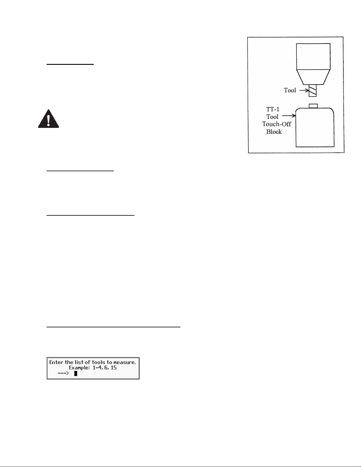
Automatic Tool Measurement
Z-minus single-surface probing, using the TT-1 tool touch-off post, is
available in the Tool Offset Library.
First Time Setup
Make sure the proper parameters are set as per Chapter 9 and Chapter 14,
and the detector is plugged in and is at the correct location on the table!
When first testing the TT-1, hold the TT-1 in hand and manually touch
the unit to the tool to confirm correct electrical connection and parameter
setup.
WARNING
Setting the Z Reference:
Using the longest tool for the job to be run or the designated reference tool, press F1- Z Ref, then F3 and then
CYCLE START. The Z-axis will then move down until the tool touch-off is detected. The Z reference will be set
at that position. Parameter 3 bit 1 is used to set Z reference to Z home position. See the parameter section in
Chapter 14 for more info.
Setting the Tool Height Offsets:
Pressing F3 – Auto Measure and then CYCLE START at the prompt will cause the Z-axis to move down until
the tool touch-off is detected; the resulting tool length will be entered in the table (same as with F2 - Manual). The
Z-axis then returns to its home position.
If Parameter 17 has been set to the number of a valid return point (1 or 2), the F3 – Auto Measure option will
move the X and Y axes to that return point before moving Z down. Return point 1 is the G28 position from the
Work Coordinate System Configuration screen (see Chapter 4). Return point 2 is the G30 position on that screen.
If Parameter 17 is zero (0), the X and Y-axes will not move before Z moves down. In this case you must be careful
to jog the machine directly over the detector before pressing F3 – Auto Measure.
Incorrect setup may cause damage to the
machine, tool and/or cause injury to the
operator.
Note: SHIFT+F3 can be used to override any return point movement in cases where parameter 17 is set to use it.
This is helpful for measuring tools wherein the height measurement is not taken from the center point of the tool.
Batch Tool Height Offset Measurement Process:
If you have both purchased the Automatic Tool Measurement (TT1) option and also have an automatic tool changer
installed, then you can press F4 - Batch to measure multiple tools in one process. After pressing F4 - Batch, you
will be prompted with the following dialogue box:
After entering a list of tool numbers, you can press CYCLE START to perform the batch tool measurement
process. This process is similar to the single tool height offset measurement (accessed via F3 – Auto Measure) but
will do multiple tools in one shot.
M-Series Operator’s Manual 12/20/13
5-3
Page 43

Setting up Tool Height Offsets
NOTICE
Using a Probe as the Reference Tool
Before you set the Z Reference, make sure the probe Tool # is entered into Parameter 12 on the Machine
Parameters screen. Make sure that Parameter 17 on the Machine Parameters screen contains a 0. Follow these steps
to probe Z Reference:
1. Load the probe into the machine.
2. Jog the probe over the desired reference surface and press F1 – Z Ref.
3. Press F3 and then CYCLE START; the probe will find the Z Reference.
At this point, the Z Reference is now entered into the Offset Library and is the reference height for all other tools.
Remove the probe and measure any other tool offsets manually as described earlier in this chapter.
Measuring Each Tool Offset Using a Fixed Detector
Before measuring any tool height, make sure you enter the probe or reference tool-measuring location. Do this by
entering a reference point number (1 or 2) into Parameter 17 and entering the detector position as the corresponding
Reference Return Point on the WCS Configuration screen. Otherwise, the machine may traverse to a location that
could damage the probe or reference tool. Also remember that if Parameter 17 is zero (0), the X and Y-axes will
not move before Z moves down. Also be sure that parameter 44 is set correctly. This is the input number for the
TT1. Now that a permanent location has been set, do the following:
Load reference tool (preferably the longest tool) and highlight its corresponding Height Offset # using the up or
down arrow keys.
Press F1 – Z Ref, then F3 – Auto Measure and then CYCLE START to set the Z reference using this tool. The X
and Y-axes will traverse to the preset location, and then Z will move down until the tool is detected and the Z
reference will be set.
Load the next tool.
Highlight the desired Height Offset # on screen using the up or down arrow keys.
Press F3 – Auto Measure and then CYCLE START. The X and Y-axes will traverse to the preset location, and
then Z will move down until the tool is detected. Once the detector is triggered, the tool offset will show on the
screen. A negative offset means the tool is shorter than the reference tool.
Once all of the tool offsets have been measured, press F10 - Save to save them. Otherwise, press ESC to cancel any
changes.
Before manually jogging any probe to a position, make sure the machine Feedrate is turned
down (less than 10 in/min) or damage to the probe may result!!!
M-Series Operator’s Manual 12/20/13
5-4
Page 44
Tool Library
Pres
PresPres
Pres
s CYCLE START to start job
s CYCLE START to start jobs CYCLE START to start job
s CYCLE START to start job
Clear
Clear Clear
Clear
FFFF
1111
Clear
Clear Clear
Clear
FFFF
2222
Tool
Tool Tool
Tool
Bin
BinBin
Bin
Ht.
Ht.Ht.
Ht.
Dia.
Dia.Dia.
Dia.
Coolant
CoolantCoolant
Coolant
Spindle
SpindleSpindle
Spindle
Speed
SpeedSpeed
Speed
Description
DescriptionDescription
Description
Tool Library
Tool LibraryTool Library
Tool Library
(from Main Screen: F1 Setup ► F2 Tool ► F1 Tool Lib)
WCS #1 (G54) Current Position (Inches)
WCS #1 (G54) Current Position (Inches)
WCS #1 (G54) Current Position (Inches) WCS #1 (G54) Current Position (Inches)
X +4.0000
X +4.0000
X +4.0000X +4.0000
Y +2.0000
Y +2.0000
Y +2.0000Y +2.0000
ZZZZ
----
T001
T001 000 H001 D0001 FLOOD
T001T001
T002
T002 000 H001 D0001 FLOOD CW 500
T002 T002
T003
T003 000 H001 D0001 FLOOD CW 500
T003 T003
T004
T004 000 H001 D0001 FLOOD CW 500
T004 T004
T005
T005 000 H001
T005 T005
T007
T007 000 H001 D0001 FLOOD CW 500
T007 T007
T008
T008 000 H001 D0001 FLOOD CW 500
T008 T008
T009
T009 000 H001 D0001 FLOOD CW 500
T009 T009
T010
T010 000 H001 D0001 FLOOD CW 500
T010 T010
0.5000
0.5000
0.50000.5000
000 H001 D0001 FLOOD CW 500
000 H001 D0001 FLOOD 000 H001 D0001 FLOOD
000 H001 D0001 FLOOD CW 500
000 H001 D0001 FLOOD CW 500000 H001 D0001 FLOOD CW 500
000 H001 D0001 FLOOD CW 500
000 H001 D0001 FLOOD CW 500000 H001 D0001 FLOOD CW 500
000 H001 D0001 FLOOD CW 500
000 H001 D0001 FLOOD CW 500000 H001 D0001 FLOOD CW 500
000 H001 D0001 FLOOD CW 500
000 H001 000 H001
000 H001 D0001 FLOOD CW 500
000 H001 D0001 FLOOD CW 500000 H001 D0001 FLOOD CW 500
000 H001 D0001 FLOOD CW 500
000 H001 D0001 FLOOD CW 500000 H001 D0001 FLOOD CW 500
000 H001 D0001 FLOOD CW 500
000 H001 D0001 FLOOD CW 500000 H001 D0001 FLOOD CW 500
000 H001 D0001 FLOOD CW 500
000 H001 D0001 FLOOD CW 500000 H001 D0001 FLOOD CW 500
D0001 FLOOD CW 500
D0001 FLOOD CW 500 D0001 FLOOD CW 500
CW 500
CW 500 CW 500
Job Name :
Job Name : bbbbracket.cnc
Job Name : Job Name :
Tool :
Tool :
Tool : Tool :
Feedrate : 100%
Feedrate : 100%
Feedrate : 100%Feedrate : 100%
Spindle : 0 M
Spindle : 0 M
Spindle : 0 M Spindle : 0 M
Stopped
Stopped
StoppedStopped
Waiting for PLC operation
Waiting for PLC operation
Waiting for PLC operationWaiting for PLC operation
racket.cnc
racket.cncracket.cnc
T001 H001
T001 H001
T001 H001T001 H001
Save
Save
Bin
Bin
BinBin
All
All
AllAll
Save Save
The definitions in the Tool Library associate tool (T) numbers with height offset (H) and diameter (D) numbers, the
default coolant type, spindle direction, and spindle speed for the tool, and a text description of the tool. This
information is used by the Intercon-programming package (described in Chapter 10) to provide defaults whenever a
tool change is selected. For enhanced ATC features, the (T) numbers are also associated with bin numbers. See
Chapter 14 for more information about enhanced ATC features (parameter 160).
Note: If enhanced ATC features are not on, the cursor cannot be moved into the bin column and the message “Bin
fields are locked.” will appear where the tool in spindle display is located. In addition, the F1 – Clear Bin and F2 –
Clear All keys only appear if enhanced ATC features are on.
You can inspect and change any of the 200 tool definitions. To edit a Tool Library definition move to the desired
tool number with the arrow keys, Page Up, Page Down, HOME, and END. To change Height Offset numbers,
Diameter numbers, default spindle speed values and the tool description, type a new value into the field and then
press ENTER. To change the default spindle direction and coolant press SPACE to cycle through the possible
values. When the changes are complete press F10 - Save to save the Tool Library and exit.
Bin
This field specifies which bin location, or ATC carousel position, that the tool is occupying. Valid values are –1
(shown as dashes “---“) through the maximum number of tools specified by machine parameter 161. A value of 0
indicates that the tool is in the spindle. The F1-F2 keys will work when the cursor is in the Bin column.
F1 - Clear Bin – places dashes “---“into the bin field (same as entering –1).
F2 - Clear All – places dashes into every bin field.
Note: For enhanced ATC applications, the bin numbers will be updated when tool changes are completed. For
random, or arm type tool changers, tools in the spindle are placed into the bin where the next tool is picked up, and
not necessarily from the bin which it was originally taken.
M-Series Operator’s Manual 12/20/13
5-5
Page 45
Height
This field specifies a default Height Offset (H) number to use with each tool. Possible values are 1 to 200.
Intercon uses this information to provide a default H value at each tool change. The CNC software also uses this
information to correct for the length of the tool that is used to establish the Z-axis position in Part Setup (see
Chapter 5).
Diameter
This field specifies a default Diameter (D) number to use with each tool. Possible values are 1 to 200. Intercon
uses this information to provide a default D value at each tool change. To change the value type a new number and
press ENTER.
Coolant
This field specifies a default coolant type to use with each tool. Possible values are FLOOD, MIST, or OFF.
Intercon uses this information to automatically insert M7 or M8 after a tool change. To change the value, press
SPACE until the desired value is shown.
Spindle
This field specifies a default spindle direction to use with each tool. Possible values are CW, CCW, or OFF.
Intercon uses this information to automatically insert M3 or M4 after a tool change. To change the value, press
SPACE until the desired value is shown.
Speed
This field specifies a default spindle speed to use with each tool. Possible values are 0 to 500000. Intercon uses
this information to automatically insert an S code after a tool change. To change the value, type a new number and
press ENTER.
Description
This field contains a text description of the tool. The description will appear in a prompt message on the screen
when the CNC software reaches a tool change (M6).
M-Series Operator’s Manual 12/20/13
5-6
Page 46
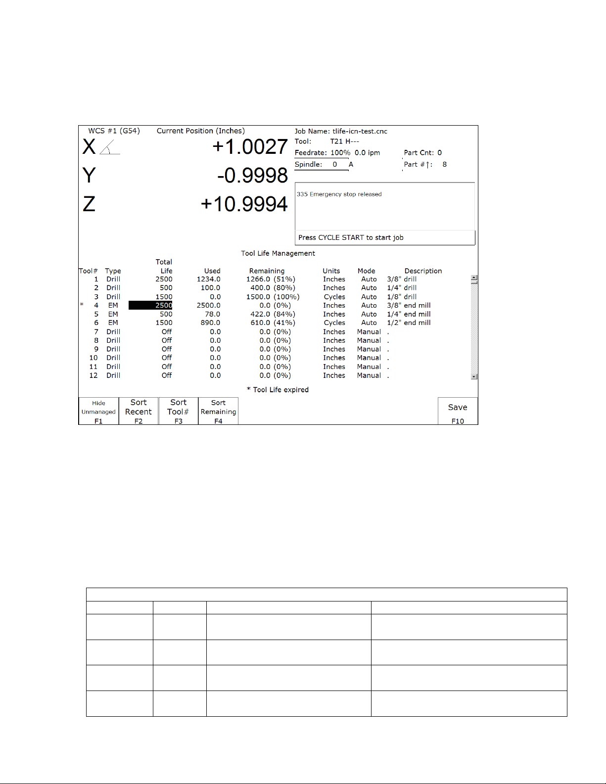
Tool Life Management menu
(from Main Screen: F1 Setup ► F2 Tool ► F1 Tool Life)
The Tool Life Management feature allows you to set up each tool’s pre-determined life, and have its usage tracked
and monitored for end-of-life condition. By default, Tool Life Management is turned off, but can be enabled for
each tool individually.
F1 – Show/Hide Unmanaged. This key toggles between including and excluding those tools that are unmanaged
by Tool Life Management. A tool is unmanaged if its Total Life field is set to value 0 (Off ).
F2 – Sort Recent. This key sorts the list according to the tools whose Total Life and/or Used field were most
recently modified by tool usage in a job run or by edits done in this menu.
F3 – Sort Tool #. This key sorts the list ordered by Tool Number.
F4 – Sort Remaining. This key sorts the list ordered by the Life Remaining.
F10 – Save. Saves changes.
A tool can be set up for automatic management by setting its Mode to Auto and setting its Total Life to a non-zero
value. The following table shows the effects of monitored tool activity on tools that are set up for automatic
management.
Automatic Management: Mode = Auto and Total Life is more than 0
Type Units Tool Activity that is monitored Effect on the ‘Used’ field
Drill Cycles downward Z plunge at feedrate at
a unique XY location
Drill Inch/mm downward Z plunge at feedrate at
a unique XY location
EM
(End Mill)
EM
(End Mill)
Cycles Tool Change ‘Used’ field will be incremented by 1
Inch/mm sideways XY feedrate moves (non-
rapid)
‘Used’ field will be incremented by 1
Cycle
Total downward Z distances minus the
overlaps will be added to the ‘Used’ field
Cycle
XY distance will be accumulated in the
‘Used’ field
M-Series Operator’s Manual 12/20/13
5-7
Page 47

Detailed description of each field is as follows.
Type
This is the type of tool – either Drill or EM (end mill). Whent the Mode field is set to Auto, this field determines
the type of tool activity that will be automatically tracked and monitored for the purpose of accounting for
consumed tool life. (See the Automatic Management table above.) Note that if the tool is a Bore or a Tap, you
should select Drill.
Total Life
This field specfies the total amount of tool life. A value greater than 0 enables Tool Life management for the tool.
A value of 0 (Off) excludes the tool from Tool Life management. Such a tool is called an “Unmanaged” tool.
Unmanaged tools can be shown or hidden by pressing F1. The units of this field is specified in the Units field.
Used
This field is the amount of consumed tool life. When a new tool is first set up, you should initialize this field to 0
indicating zero usage. If the Mode field is set to Auto, this field will automatically be modified during a job run to
reflect the accumulated tool usage. The units of this field is specified in the Units field.
Remaining (non-edit)
This is the display of the remaining amount of tool life.
Units
This specifies the units (either distance or Cycles) that will be used and displayed for the Total Life, Used, and
Remaining fields. Distance is specified with mm or Inches (as set in the Control Configuration menu – see Chapter
14).
Mode
This specifies the update mode of the Used field -- either Auto or Manual. If this field is set to Auto, then tool
activity is montiored during a job run for tool usage which will be automatically accumulated in the updated Used
field. (See the Automatic Management table above.)
If this field is set to Manual, no such automatic updates will take place on the Used field. Rather, updates to the
Used field will be dependent upon user variable modifications programmed in the G-code program being run. (See
the section Tool Life Management – Using G-Code User Variables later in this chapter.)
Description
This field contains a text description of the tool. The description will appear in a prompt message on the screen
when the CNC software reaches a tool change (M6) during a job run.
M-Series Operator’s Manual 12/20/13
5-8
Page 48
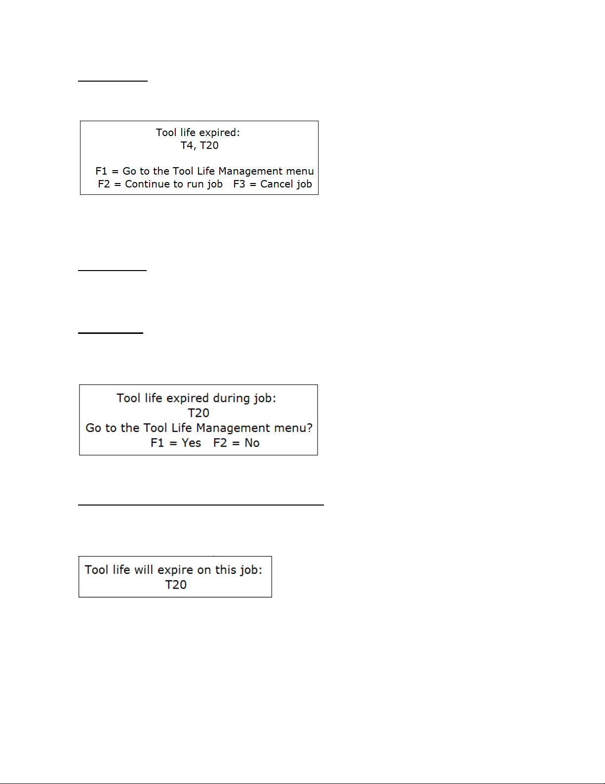
Tool Life Management – Effect on Job Run and Backplot
At Start of Job
Tool life expirarations will be checked at the beginning of a job run. If any managed tools are expired at the
beginning of a job, the following dialog will show up and you will have one of 3 choices to make:
When a job is first started, the CNC software will not yet know which tools are going to be used in the job until the
job is successfully completed. Therefore, the tools listed here will be the list of all expired tools even if they are not
going to be used in the job.
At Job Restart
Tool life expirations are also checked upon job restart (i.e. upon encountering M2 or M102). If any tool(s) expired
during the previous job run (previous to the M2 or M102), then the dialog that is displayed is similar to that shown
above except that the expired tools listed will only be the ones that were used in the job.
At End of Job
When tool life expires during a job, such an event will not cancel the job. Instead, upon successful end of the job
the following dialog will be displayed and you will have an opportunity to quickly get to the Tool Life Management
menu:
This end-of-job dialogue will show only the expired tools that were used in the job.
Using Backplot Graphics to Predict Tool Expirations
You can use Backplot Graphics as a way to predict ahead of time whether or not one or more tools will expire
during a job. Simply press F8 Graph at the Main Screen or in the Load menu. If the job being graphed will result
in an expired tool if it was actually run, then the following message will show up:
M-Series Operator’s Manual 12/20/13
5-9
Page 49

Tool Life Management – Using G-Code User Variables
If a tool’s Mode field is set to Manual, there will be no updates to the Used field of the Tool Life data during a job
run, unless the job’s G-code is programmed to modify it.
The following is an example of how a G-code program would modify tool life data. Assuming tool T23’s Mode is
set to Manual, and its Units is set to Cycles, the following G-code will increment T23’s Used Life field by 1 after
completing the example_cycle.cnc.
M6 T23 ; change tool to T23
M98 "example_cycle.cnc" L1 ; run the cycle 1 time
IF #4201 || #4202 THEN GOTO 100 ; skip to N100 if in backplot or search mode
IF #4120 < 1 || #4120 > 200 THEN GOTO 100 ; skip to N100 if T number is not valid
#[19000+[#4120-1]*5+2] = #[19000+[#4120-1]*5+2] + 1 ; increment current tool's Used Life by 1 cycle
N100 ; destination of goto’s
See Chapter 11 for more information about the use of User or System Variables.
M-Series Operator’s Manual 12/20/13
5-10
Page 50
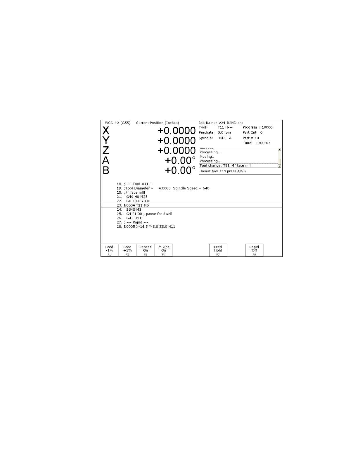
Chapter 6
Running a Job
To start the currently loaded job, go to the Main Screen and press the CYCLE START button on the jog
panel. If your control is not equipped with a jog panel, press ALT-S on the keyboard.
Active Job Run Screen with G-code Display
If the Run-Time Graphics option is set to Off, the following screen is displayed while a job is running:
On this screen, the following F-keys are available:
F1 – Feed (-1%)
F2 – Feed (+1%)
F3 – Repeat On/Off
F4 – Skips On/Off
F5 – Auto
F6 – Stops off
F7 – Feed Hold
F8 – Graph
F9 – Rapid On/Off
For information on other keys that are available while a job is running, see Chapter 2.
M-Series Operator’s Manual 12/20/13
Decrease feedrate override by 1%. (Available only if keyboard jogging is active.)
Increase feedrate override by 1%. (Available only if keyboard jogging is active.)
Toggle the repeat feature for part counting. For more information, see F3 under the
Run Menu section later in this chapter.
Enable/Disable block skips. For more information, see F4 under the Run Menu
section later in this chapter.
This key will only appear in Single Block mode. When you press this key, it turns
on Auto mode and disables Single Block mode. Once Auto mode is turned on,
Single Block cannot be re-enabled unless you stop the job. For more information,
see F5 under the Run Menu section later in this chapter.
This key will only appear if Optional Stops is on. When you press this key, it turns
off Optional Stops. Once Optional Stops is turned off, it cannot be re-enabled
unless you stop the job. For more information, see F6 under the Run Menu section
later in this chapter.
Turn feed hold on/off. (Available only if keyboard jogging is active.)
Switch to run-time graphics screen. This key only appears if the job was started with
the run-time graphics option turned on.
Turn rapid override on/off.
6-1
Page 51
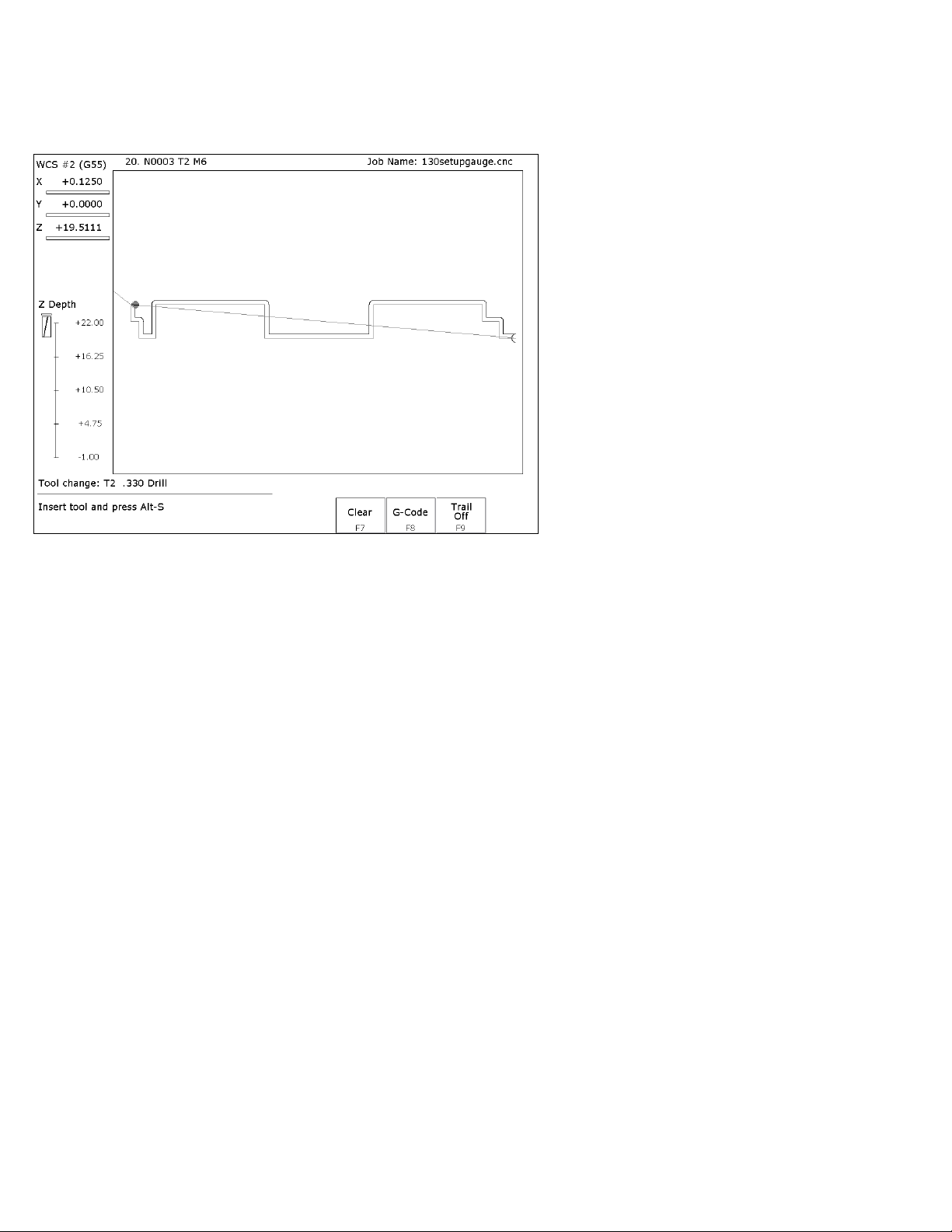
Run-Time Graphics Screen
When a job is running with Run-Time Graphics set to On, the following screen is displayed:
The following keys are available while the job is running in Run Time Graphics.
F7 – Clear
F8 – G-Code
F9 – Trail On/Off
Clears the trail up to the tool’s current position in the program.
Switch to the Job Run Screen with G-Code display.
Turn on/off the tool trail display.
Canceling a Job in Progress
There are three conventional ways to cancel a currently running job (CNC program). When a job is canceled
using any of the following methods, the job's progress will be recorded. This allows the user to restart the
job using the Resume Job option or the Search and Run option.
CYCLE CANCEL pressing this key while a job is running will cause the control to abort the job
currently being run. The control will stop movement immediately, clear all M-functions, and
return to the main screen. Hitting the escape key on the keyboard is equivalent to hitting
“CYCLE CANCEL.”
TOOL CHECK Pressing this key while a job is running will cause the control to stop the normal
program movement. In addition, the Z-axis will be pulled to its home position and all Mfunctions will be cleared. The control will automatically go to the resume job screen.
EMERGENCY STOP (E-Stop) Pressing the EMERGENCY STOP button, while a job is running,
will cause the control to abort the job currently being run. The control will stop movement
immediately, clear all M-functions, and return to the main screen. Also, the power to all axes will
be released.
M-Series Operator’s Manual 12/20/13
6-2
Page 52
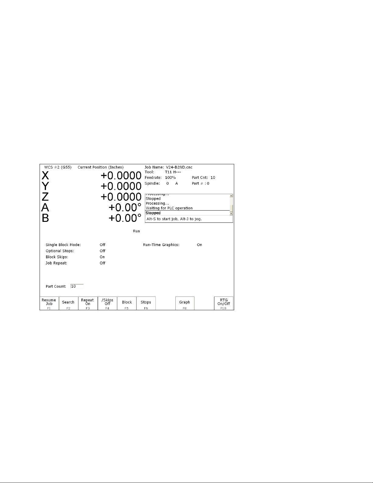
Resuming a Canceled Job
If a job is canceled using one of the methods described above, it can be resumed in one of three ways:
CYCLE START Pressing the CYCLE START button will restart the job at the BEGINNING of the
part program.
F1 - Resume Job (Located in F4-Run menu) Restart the canceled job at or near the point of
interruption. See the next section in this chapter entitled “Run menu” for more information.
F2 - Search (Located in F4-Run menu) Restart at a specified point in the part program. See the next
section in this chapter entitled “Run menu” for more information.
Run menu
Press F4 - Run from the main screen to access the Run menu. From this menu, the operator can restart a
canceled job or change the way the job will run.
F1 - Resume Job Access the resume job screen by pressing F4 - Run on the main screen to go to the
run screen, and then pressing F1 – Resume Job in the run screen to go to the resume job screen.
If the job was canceled by pressing TOOL CHECK, the control will go to the resume job screen
automatically. From this screen, the user can modify tool offsets and the tool library, turn block
mode on and off, turn optional stops on or off, graph the partially completed job, or start the
partially completed job.
The resume job option is not always available. The following situations will cause the resume job option to
be unavailable:
• Loading a new job.
• Running a job to completion.
• Parse errors in the job.
• Editing or reposting the job file.
• Loss of power while a job is running.
M-Series Operator’s Manual 12/20/13
6-3
Page 53

F2 – Search Invoking this option will bring you to the “Search and Run” menu. This menu will allow
you to specify the program line, block number, or tool number at which execution of a program is
to begin. Program lines are numbered from the top of the file down with the first line numbered
1. To enter a block number, place an "N" in front of the number. To enter a tool number, place a
"T" in front of the number. Pressing CYCLE START from here would start the program at the
point you specified.
An extra option unique to the “Search and Run” screen is the F1 – Tool Change “Do Last Tool
Change” function. This key toggles the tool change option as shown on screen. A "YES" tells
the control to perform a tool change so that the tool specified for the line or block has the tool
indicated in the program. A "NO" uses the currently loaded tool, regardless of what tool is
specified for the line or block being searched.
NOTE: You cannot search into a subroutine.
F3 – Repeat On/Off This key toggles the repeat feature for part counting. When part counting is in
effect and Repeat is on, the job will be automatically run again until the specified number of parts
has been run. The On or Off label indicates the state to which the repeat feature will toggle to
when pressed. It does not indicate the current state. The current state is indicated in the user
window above.
The Part Count: prompt is used to set the Part count. Positive values set the part counter to count up and
negative values configure the part count to count down. For example, if 10 is entered in the Part Count
prompt, the Part Cnt in the status window changes to 10 and the Part # changes to 0 with an upward arrow
indicator. When a job is run and then completes, the Part # will increment to 1. If repeat is on, the job will
automatically start again and keep running until the Part # has reached the Part Cnt. If a –10 is entered in the
Part Count prompt, the Part Cnt in the status window changes to 10 and the Part # changes to 10 with a
downward arrow indicator. When a job is finished, the Part # will decremented to 9. If repeat is on, the job
will automatically start again and keep running until the Part # has reached 0.
F4 - /Skips On/Off This function toggles the block skip feature. When block skipping is on, G-code
lines that start with a forward slash character ‘/’ are skipped, i.e., they are not processed. Note
that because of the way a job is processed (in a pre-processed buffered fashion) the effect of this
key may be delayed if you press it while a job is running. The On or Off label indicates the state
to which the /Skips feature will toggle to when pressed. It does not indicate the current state. The
current state is indicated in the user window above.
F5 - Block Mode Turns single block mode on and off. This is similar to pressing AUTO/BLOCK. If
Single Block mode is on, the CNC software will stop after each block in your part program and
wait for you to press CYCLE START. Note that Auto mode is the default mode. If you use this
key to turn on Single Block mode and then run a job, Auto mode will be re-instated when the job
ends. The current state of this setting is indicated in the user window above.
F6 - Optional Stops Turns optional stops on and off. If optional stops are on, any M1 codes that
appear in your program will cause a wait for CYCLE START (just like M0). If optional stops
are off, M1 codes will be ignored. Note that the default mode for Optional Stops is off. If you use
this key to turn on Single Block mode and then run a job, Optional Stops will be set to off when
the job ends. The current state of this setting is indicated in the user window above.
M-Series Operator’s Manual 12/20/13
6-4
Page 54

F8 – Graph Graphs the part. For more information, see the "F8 - Graph" section in chapter 3. If this
feature is invoked from the Run and Search screen or the Resume Job screen, then the graphics
will show exactly where the searched line or block begins. Dotted lines indicate the portion of the
part that is skipped. Solid lines indicate the portion of the part that will be machined.
F9 – Rapid On/Off This function key toggles Rapid Override. The On or Off label indicates the state
to which the Rapid Override feature will toggle when pressed. In the Rapid Override On state,
the speed of rapid moves (G0) can be adjusted by the Feedrate Override knob. In the Rapid
Override Off state, the speed of rapid moves will be at full speed (max rate).
F10 – RTG On/Off This function key toggles the Run-Time Graphics option. If the option is turned
on, Run-Time Graphics automatically starts when the CYCLE START button is pressed. This
option must be turned on for Run-Time Graphics to be used. If the option is turned off, RunTime Graphics cannot be started while a job is running.
Power Feed
Press F4 - Feed from the Setup menu to access the Power Feed screen. This screen is used to command axis
movement. All the operations available on the Power Feed screen may also be performed in MDI with the
appropriate M and G codes.
F1 - Absolute Power Feed Press F1 - ABS to move an axis to an absolute position, at a specified
feedrate.
F2 - Incremental Power Feed Press F2 - INC to move an axis an incremental distance, at a specified
feedrate.
F3 - Free XY Press F3 - Free to release power to the X and Y motors, allowing you to use your
machine manually for these two axes.
F4 - Power XY Press F4 - Power to apply power to the X and Y motors, allowing you to use your
machine with the jog panel for these two axes.
M-Series Operator’s Manual 12/20/13
6-5
Page 55

M-Series Operator’s Manual 12/20/13
6-6
Page 56
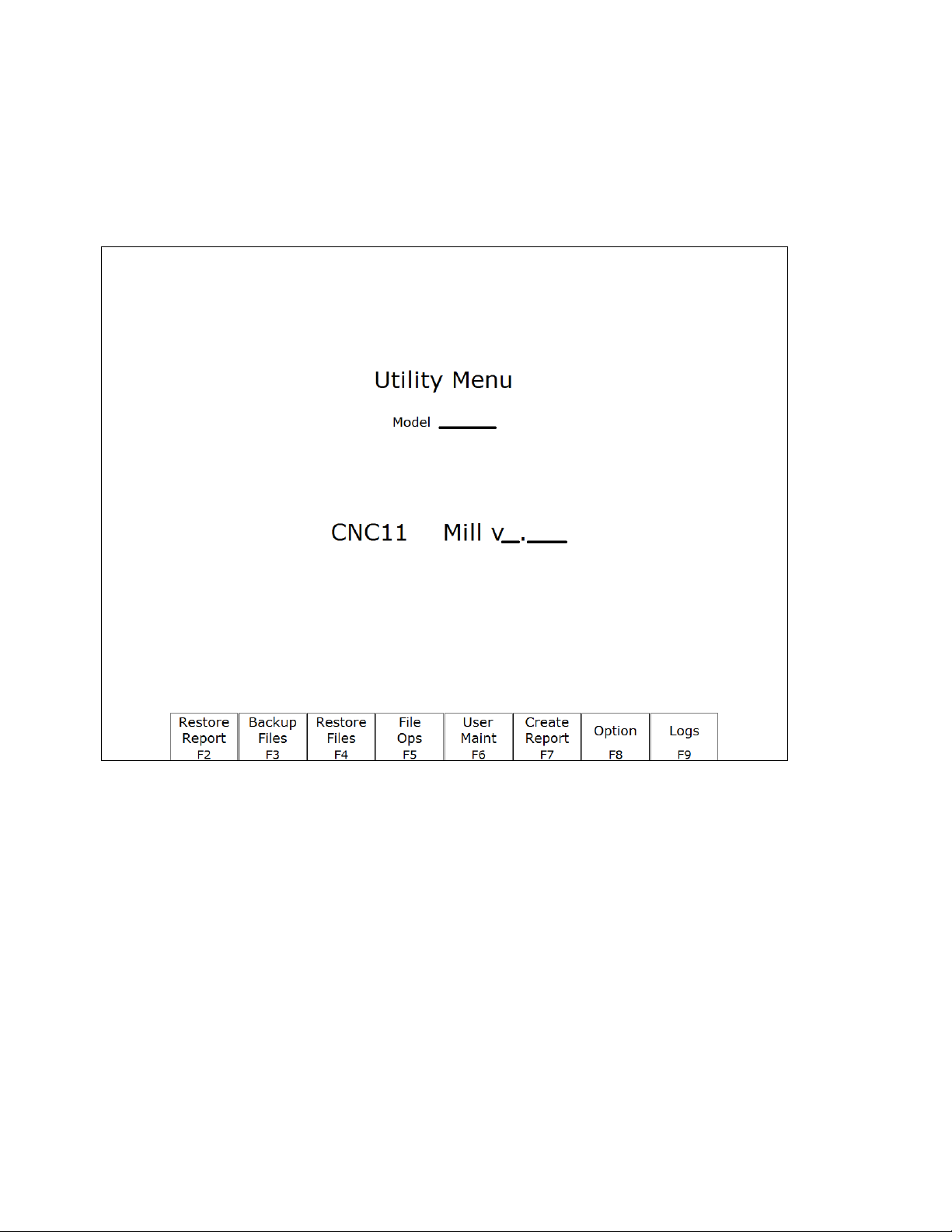
Chapter 7
The Utility Menu
To get to the Utility Menu, press F7 - Utility at the CNC software Main Screen. The model will vary depending on
your M-Series Control model.
F2 – Restore Report This option is used primarily for restoring a system configuration from a previously
saved report.zip file (See F7 – Create Report).
F3 – Backup Files This creates an archive file “cnc_backup.zip” containing CNC program files, Intercon
part program files, MillWrite engraving files, and digitized output files from the following
directories and their subdirectories: ncfiles directory, c:\intercon, c:\mw, and any other
directories mentioned in the pathm.ini configuration file.
F4 – Restore Files Use this option to restore the data previously backed up with F3 – Backup Files. (Note
that this feature will not work with backups created by control software prior to version 3.04.)
M-Series Operator’s Manual 12/20/13
7-1
Page 57
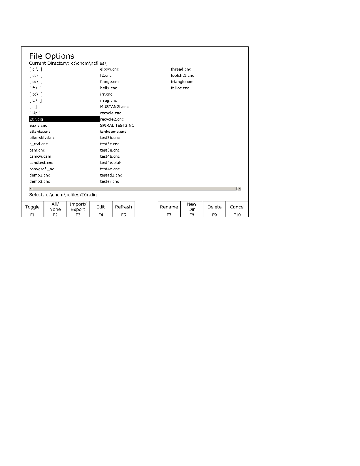
F5 – File Ops Use this menu to perform file and directory operations such as: Importing and Exporting
(copying) files to and from the control, rename or delete files, create or delete directories.
F1 – Toggle
F2 – All /None
F3 – Import/
Export
F4 – Edit
F5 – Refresh
F7 - Rename
F8 - New Dir
F9 - Delete
Page Up
Page Down
End
Home
Arrow Keys
Press once to select or press again to unselect a single file.
Press once to select all or press again to unselect all files.
Import or Export selected files.
Opens selected file in editor.
Refresh file list. Use after inserting a new USB storage device
Rename selected file or directory.
Create a new directory in the current folder.
Deletes selected file or directory.
Move the cursor backward one page.
Move the cursor forward one page.
Select the last file in the list.
Select the first file in the list.
Move the cursor in the selected direction.
M-Series Operator’s Manual 12/20/13
7-2
Page 58

F6 – User Maint
Use this menu to perform user maintenance such as checking an axis for excessive drag or setting
backlash
F1 – Drag The Drag Factor utility is used to determine if an axis has an excessive amount of drag. To
run a drag test, use the F1 key to select the axis which you wish to test, position the axis at or near
the home position and press CYCLE START. The axis will move back to the home switch then
traverse the entire range of travel for the axis moving to the opposite limit and returning to home
while moving the slow jog rate. If excessive friction (drag) is encountered an error message will
be displayed. When the test completes, use F8-Graph to display the results. The red horizontal
lines indicate the bounds acceptable limits for the machine as it is currently configured.
F2 - Lash (Backlash Compensation) In order to insure an accurate measurement always set the backlash
compensation in the control to zero before attempting to measure the physical lash in an axis.
F7 – Create Report Generates a backup of system configuration files called report.zip and copies it to the
specified location. Your dealer may then use this file for servicing and troubleshooting purposes.
To restore the configuration files from the report disk, press F2 – Restore Report from the
Utility menu.
F8 – Options Shows the software options that you have purchased or added to your control. On this screen
you can also enter unlock codes for software options that you have purchased. This page will
also display the PLC programs, PIC type, and System ID #.
F9 – Logs Shows the messages and errors that have been logged by the control.
F1 – Errors Displays the error/message log. Use PgUp, PgDn, Home, & End to view and ESC to exit.
F2 – Stats Displays counts of errors logged. Use PgUp, PgDn, Home, & End to view and ESC to exit.
F3 – Export Exports the log to a destination of your choosing.
M-Series Operator’s Manual 12/20/13
7-3
Page 59

M-Series Operator’s Manual 12/20/13
7-4
Page 60
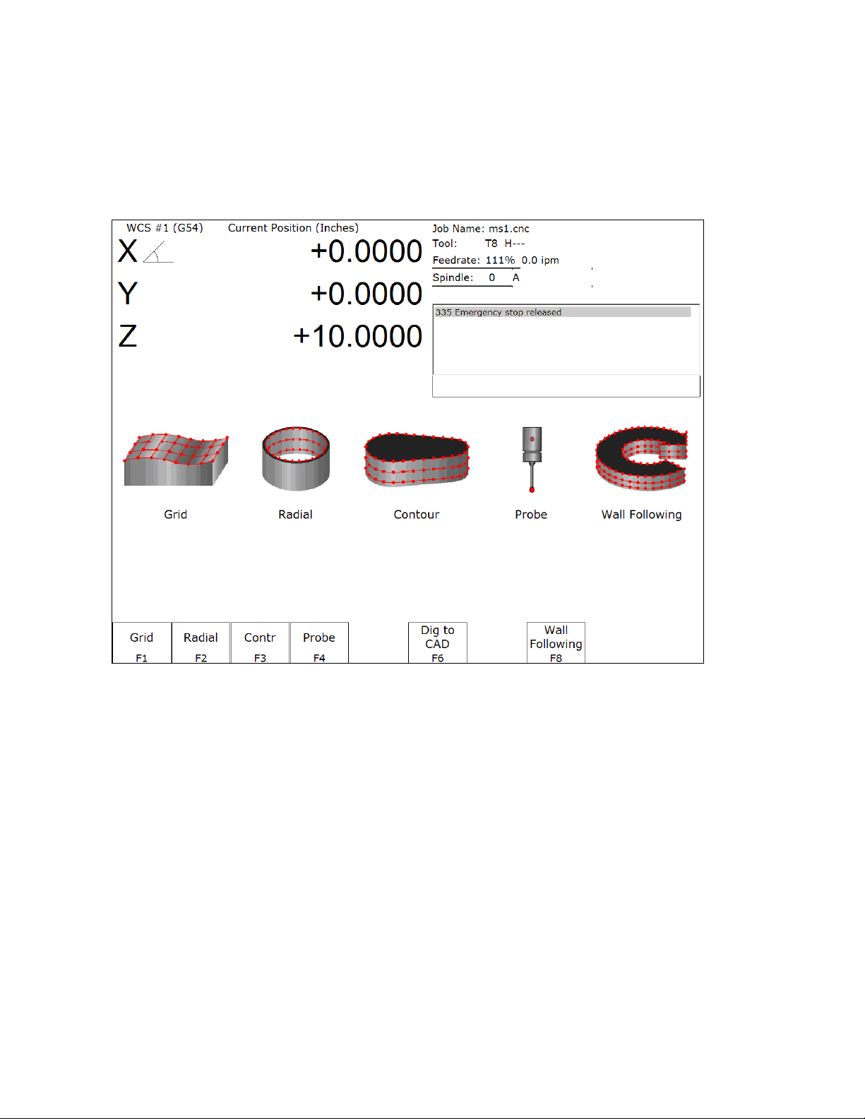
Chapter 8
Digitize
(F9 from Main Menu)
The Digitize feature of the CNC software can be used to digitize surfaces in a variety of scenarios. The digitizing
process creates a file with M & G codes that represent the digitized surface. If the digitizing probe tip is chosen to
match the milling cutter size, the digitized file can be loaded and run to produce an exact copy of the digitized part.
F1 – Grid
F2 – Radial
F3 – Contour
F4 - Probe
F6 – Dig to CAD
F8 – Wall Following
M-Series Operator’s Manual 12/20/13
Digitize rectangular surface area.
Digitize inside of a bore.
Digitize inside or outside contour.
Select from the Probing Cycles (See Chapter 9 of this manual).
Export digitized files for use with a CAD/CAM system.
Digitize inside and/or outside contour .
8-1
Page 61
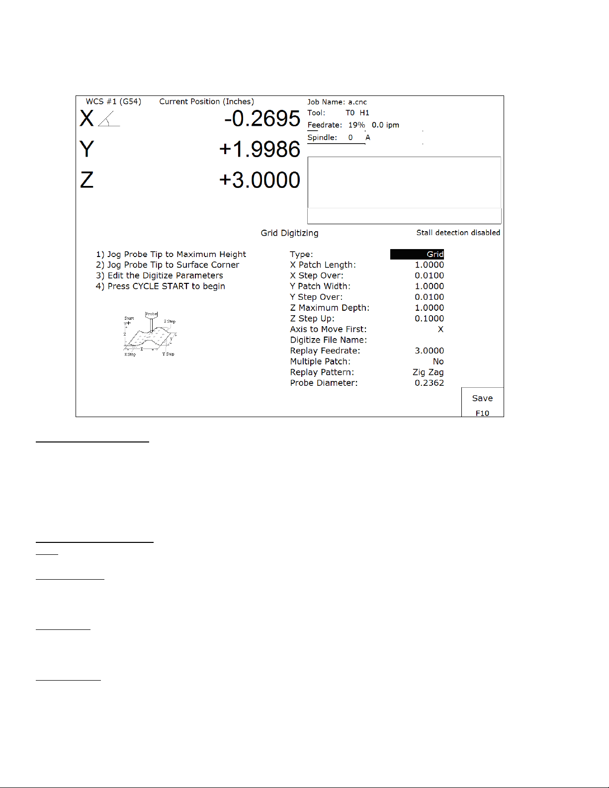
Grid Digitize
(F1 from Digitize Menu)
Grid Digitize Run Setup
To set up a digitizing run, edit the parameters shown and then press CYCLE START. The control will move
through the area to be digitized in a rectangular pattern. At each X-Y point in the pattern, it will measure the Z
height of the sample surface, and record the coordinates in the data file.
Digitizing begins at the current tool position when the CYCLE START button is pressed. This position should be
in one corner of the digitize area, at a Z position higher than any point on the surface.
Grid Digitize Parameters
Type: This sets the algorithm for digitizing: either regular Grid or Surface Following.
X Patch Length: The length of the area to be digitized, along the X-axis. A positive value will cause digitizing to
proceed in the X+ direction from the starting point; a negative value will cause digitizing to proceed in the Xdirection. If the value is 0, then digitizing will collect just one stripe along Y.
X Step Over: The distance to move between points on the X-axis. A smaller value should be used for a fine
digitize along the X-axis. A larger value should be used for a rough digitize along the X-axis. This distance should
be a positive incremental value.
Y Patch Width: The width of the area to be digitized, along the Y-axis. A positive value will cause digitizing to
proceed in the Y+ direction from the starting point; a negative value will cause digitizing to proceed in the Ydirection. If the value is 0, then digitizing will collect just one stripe along X.
M-Series Operator’s Manual 12/20/13
8-2
Page 62

Y Step Over: The distance to move between points on the Y-axis. A smaller value should be used for a fine
digitize along the Y-axis. A larger value should be used for a rough digitize along the Y-axis. This distance should
be a positive incremental value.
Z Maximum Depth: The maximum distance the Z-axis moves below the starting height. If the probe does not
contact the surface at the maximum depth, that data point will be recorded as being at the maximum depth, and
digitizing will proceed with the next point.
Z Step Up: The distance the Z-axis moves up after making contact, before the control attempts to move X or Y. A
small value should be used when digitizing parts with gentle slopes; a larger value should be used when digitizing
parts with many steep walls.
Axis to Move First: The axis (either X or Y) which moves all the way across the digitize area with each pass.
Digitize File Name: The base name of the output file in which the digitize data is stored. An extension of .dig will
automatically be appended to the name for replay as a CNC job.
Replay Feedrate: The feedrate to include with the G1 command on the first line of the data file. If the data file is
run as a CNC program, this is the feedrate at which the machine will retrace the digitized surface.
Multiple Patch: Indicates whether or not this digitizing is a continuation of an earlier digitizing. Choose NO if the
current digitizing is the first or only digitize run for the part to be digitized. Choose YES if the current digitizing is
not the first digitize run for the part. If Yes is selected, specify the name of a digitize file of a previous multiple
patch.
Replay Pattern: Indicates the replay movement pattern. If ZIG ZAG is selected, the replay pattern will alternate
between positive and negative directions on each successive pass. If ONE WAY is selected, the replay pattern will
maintain a constant "one-way" direction throughout the playback.
Probe Diameter: Indicates the probe tip diameter.
M-Series Operator’s Manual 12/20/13
8-3
Page 63
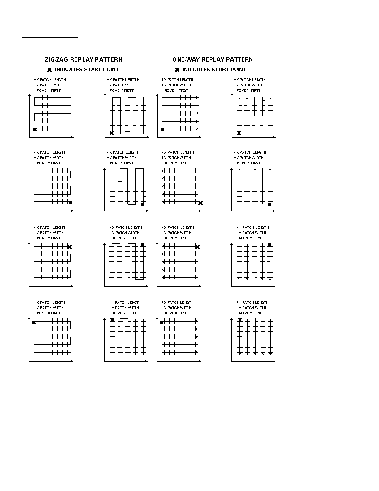
Grid Digitize Notes
1. A guide to the possible grid digitizing paths is as follows:
2. A digitizing patch can be located anywhere in the coordinate system. The digitizing starting point is referenced
from the part zero. For example, setting up digitizing, as shown in the figure on the right below, will record the
first point at (X5, Y5, Z1) and the last point at (X7, Y7, Z1). If the digitizing replay starting point is desired to be at
the part zero be sure to set the part zero equal to the digitizing start point, as shown in the figure on the left below.
This orientation will record the first point at (X0, Y0, Z0) and the last point at (X2, Y2, Z1). For more information
on part setup see Chapter 4.
M-Series Operator’s Manual 12/20/13
8-4
Page 64
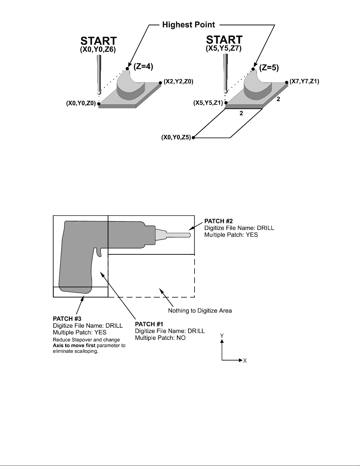
3. A good technique for calculating Z maximum depth is to touch off the lowest surface of the part to be digitized
and set the part zero's Z value to Z0. Then jog the probe tip to a point higher than the highest surface of the part to
be digitized. Note the displacement in the Z-axis. Again, set this Z height to Z0 and use the noted displacement for
the Z maximum depth.
4. Multiple patches are useful in the following situations: completing a canceled digitize run, digitizing parts with
large areas that contain nothing to be digitized (shown below), and patching vertical walls to eliminate scallops
caused by the cutting tool.
The drill shown in the previous example is L-shaped. Therefore, it can be digitized faster and more efficiently
using three rectangular patches than digitizing the complete area with a single patch.
Digitizing the entire part and then adding multiple small patches along the walls can avoid vertical wall scalloping.
If a vertical wall extending along the X axis needs to be cleared of scallops, just add a small patch running the
length of the wall. Set the “Axis to Move First” parameter to Y. This will clear the scallops.
M-Series Operator’s Manual 12/20/13
8-5
Page 65
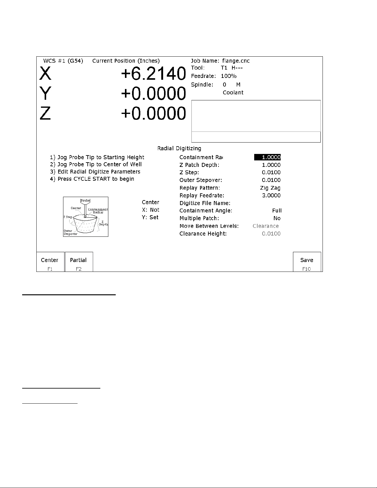
Radial Digitize
(F2 from Digitize Menu)
Setting up a Radial Digitize Run
To set up a digitize run, edit the parameters shown. Jog the probe tip to the starting height and to the center of the
bore to be digitized. Then press F1 - Center to define the center position for digitizing. This center position will
be used as the center of all radial digitizing runs until you leave the radial digitize menu or redefine the center. If
you are using a full angle, you can now press CYCLE START to begin digitizing. If you have specified partial
angle, press F2 - Partial to define the partial angle (see setting the partial angle section in this chapter). After
defining the partial angle, pressing CYCLE START will start the digitize run.
WARNING: The probe must be able to retreat to the center from any position on the digitize surface. If the
digitize surface contains features that do not allow for the probe to exit after entering, a probe crash may
occur! See radial digitize note 2 later in this section.
Radial Digitize Parameters
Containment Radius: The maximum distance from the center position to look for a digitize data point. This
parameter is used to contain the probe within a circle with this radius centered at the center position. If the probe
does not contact the surface before reaching the maximum radius that data point will be recorded as being at the
maximum radius, and digitizing will proceed with the next point.
M-Series Operator’s Manual 12/20/13
8-6
Page 66

Z Patch Depth: The depth of the patch to be digitized, along the Z-axis. A positive value will cause digitizing to
proceed in the Z+ direction from the starting point; a negative value will cause digitizing to proceed in the Zdirection.
Z Step: The distance to move between points on the Z-axis. A smaller value should be used for a fine digitize
along the Z-axis. A larger value should be used for a rough digitize along the Z-axis. This distance should be a
positive incremental value.
Outer Stepover: The distance to move between points on one contour. A smaller value should be used for a fine
digitize along any one contour. A larger value should be used for a rough digitize along any one contour. This
distance should be a positive incremental value.
Replay Pattern: Indicates the replay movement pattern. If Zigzag is selected, the replay pattern will alternate
between positive and negative angle directions (CW and CCW) on each successive contour. If CW or CCW is
selected, the replay pattern will maintain a constant angle direction throughout the playback.
Replay Feedrate: The feedrate to include with the G1 command on the first line of the data file. If the data file is
run as a CNC program, this is the feedrate at which the machine will retrace the digitized surface.
Digitize File Name: The base name of the file in which the digitize data is stored. The file has an extension of .dig
for CNC replay.
Containment Angle: Indicates whether or not the digitizing is to follow a full circle or a partial sector. Choose Full
if 0 to 360 degrees is desired. Choose Partial if some other angles are needed. These partial angles can then be
changed later (see setting the Partial Digitizing Sector Setup section that follows).
Multiple Patch: Indicates whether or not this digitizing is a continuation of an earlier digitizing.
Choose No if the current digitizing is the first or only digitize run for the part to be digitized. Choose Yes if the
current digitizing is not the first digitize run for the part. If Yes is selected, specify the name of a digitize file of a
previous multiple patch.
Move Between Levels: This field is enabled only if Partial and CCW or CW option is selected. It indicates the
move between Z levels on replay of a partial sector radial digitize file. This move may now be done in three
different ways: Clearance, which goes to the clearance height as in previous versions, Center, which goes to the
digitizing center and then to the Z level of the next pass, and Direct, which goes directly to the starting point of the
next pass.
Clearance Height: This field is enabled only if Partial, CCW or CW replay pattern, and Clearance Move type
option is selected. This distance indicates the clearance height needed to move the cutter from the end of one
contour to the beginning of the next contour. This distance should be a positive value.
M-Series Operator’s Manual 12/20/13
8-7
Page 67
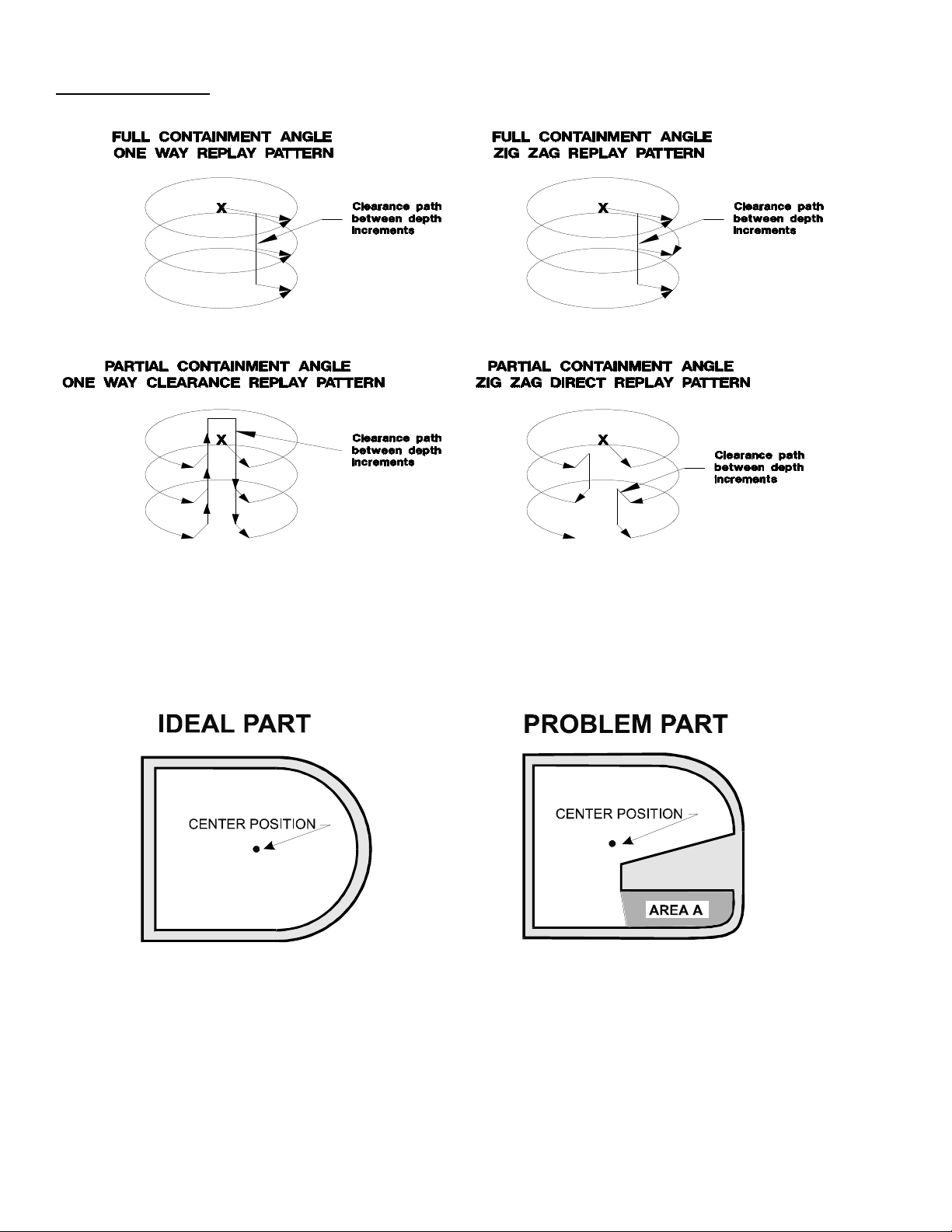
Radial Digitize Notes
1. A guide to possible radial digitizing paths is as follows:
2. When radial digitizing, make sure the probe can fully retract to the center position without obstructions.
Observe the two parts below. The cross section on the left has no obstructions that could keep the probe from full
retraction to the center position. The cross section on the right does not allow the digitizing to retract to the center
in Area A. This area will cause a probe crash; single patch digitizing of parts such as this should be avoided. Use
2 or more patches to digitize the part on the right (in this case, you could divide the part in half horizontally, and do
each half separately).
M-Series Operator’s Manual 12/20/13
8-8
Page 68
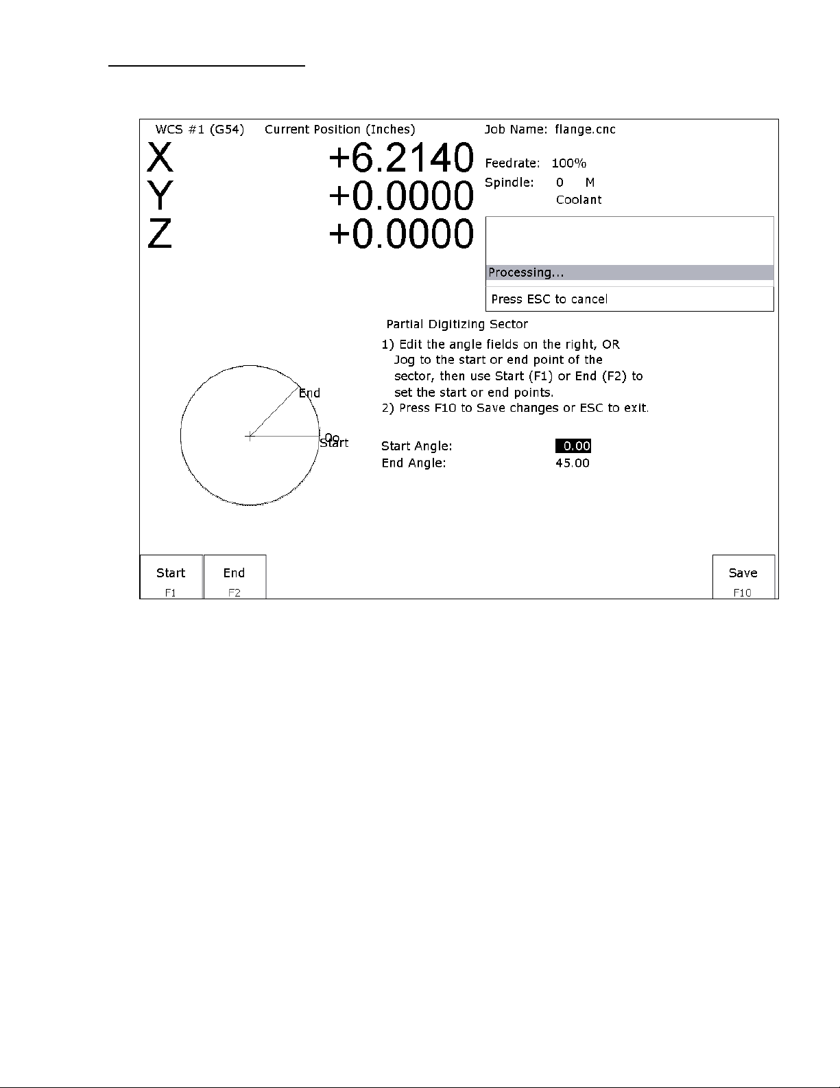
Partial Digitizing Sector Setup
If you set the Radial Digitize Containment Angle to “Partial” then you must set up the Digitizing Setup by pressing
F2 - Partial from the CNC software Radial Digitize Screen.
The partial sector can be setup one of two methods:
One method is by editing the start and end angles directly. The start angle is referenced from zero degrees and
defines the beginning of the digitizing sector. The end angle is referenced from zero degrees and defines the end of
the digitizing sector.
The second method involves jogging the probe tip and touching off the digitize surface. By moving the probe tip to
positions on the digitizing surface, one can set the angles. To set the start angle, jog the probe tip to the position on
the digitizing surface where the digitizing is to begin and press F1 - Start to define this as the start angle. * Notice
that the picture of the sector and the start angle's value change to reflect these settings. To define the end angle,
follow the procedure above but press F2 - End instead to set the end angle.
Regardless of the method used to define the start and end angles, pressing F10 - Save saves the angles and exits
back to the radial digitize menu. Pressing ESC will return to the radial digitize menu without making changes to
the start and end angles.
M-Series Operator’s Manual 12/20/13
8-9
Page 69
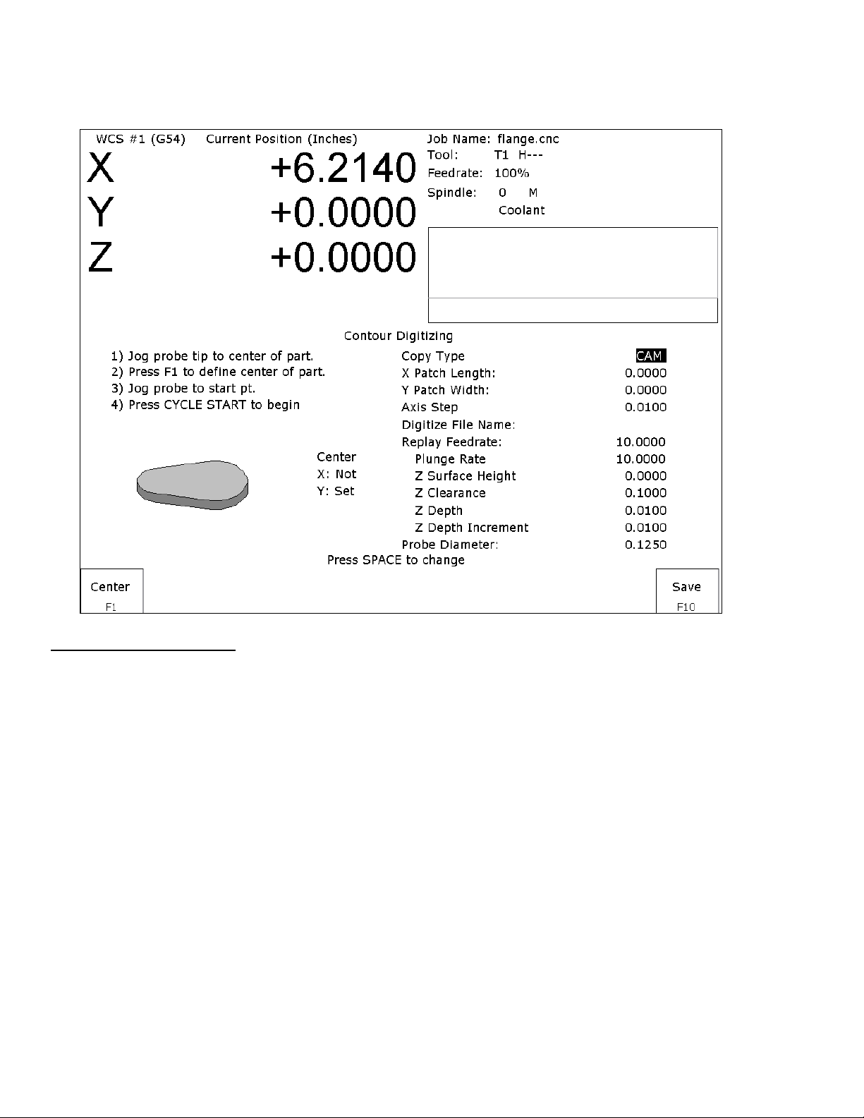
Contour Digitize
(F3 from Digitize Menu)
Contour Digitize Run Setup
To set up a digitizing run, jog the probe tip to the center of the part and hit F1 - Center to assign that as your center
point.
Select CAM for a true CAM shape contour, or Wall for irregular shapes for wall following. Enter the rest of the
parameters for the part and digitizing job as shown below.
Jog the probe to a starting point and press CYCLE START. The control will move the probe toward the center line
in the +/- X direction until it comes into contact with the part. At each point of contact, the X and Y coordinates
will be recorded in the data file.
The probe will continue around the contour until it returns to the starting point to complete the cycle. Based on the
starting point, and the first point of contact, the digitize software will determine if the contour is internal or
external.
Important note: When probing an external contour, make sure the probe comes in contact with part on the first
move. If it doesn’t, the software will compensate to the outside of the part as if it were an internal contour causing
your part to come out larger than you want it to be.
M-Series Operator’s Manual 12/20/13
8-10
Page 70
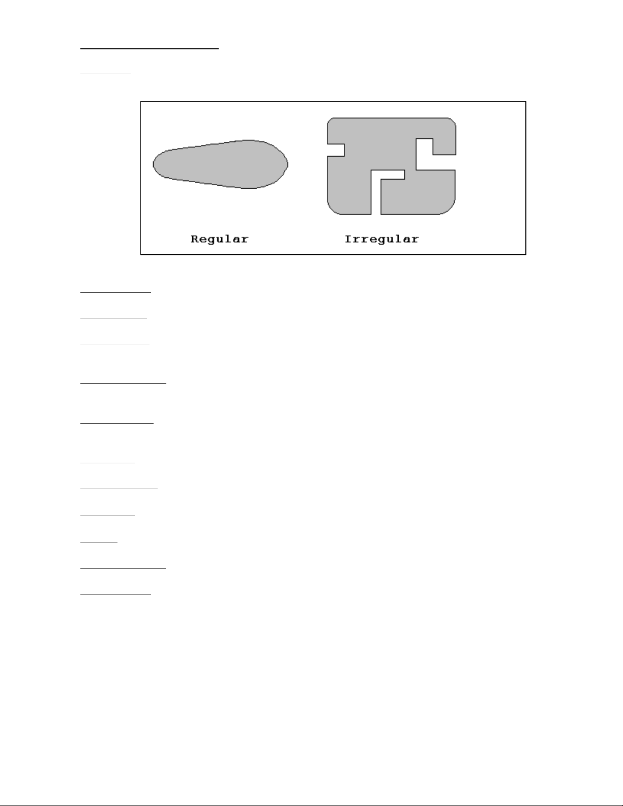
Contour Digitize Parameters
Copy Type: Toggle between CAM or Wall. Use CAM for regular shapes (no extreme direction changes) and use
Wall following for contours with irregular shapes. See example below.
X Patch Length: The length of the contour to be digitized, along the X-axis.
Y Patch Width: The width of the contour to be digitized, along the Y-axis.
Axis Step Over: The distance to pull back away from the surface in the X and/or Y direction. A larger value
should be used for a rough digitize along the Y-axis. This distance should be a positive incremental value.
Digitize File Name: The base name of the file in which the digitize data is stored. The file has an extension of
.cam for CNC replay and is stored in the c:\cncm\ncfiles directory.
Replay Feedrate: The feedrate to include with the G1 command on the first line of the data file. If the data file is
run as a CNC program, this is the feedrate at which the machine will retrace the digitized surface.
Plunge Rate: The feedrate the Z axis plunges between successive depth passes.
Z Surface Height: Surface height of material for reproduction of digitized parts.
Z Clearance: Clearance to rapid to above surface of part during replay.
Z Depth: Depth of the part as measured from the surface height.
Z Depth Increment: Depth of cut for each Z step of the part.
Probe Diameter: Diameter of probe tip used to digitize the part.
M-Series Operator’s Manual 12/20/13
8-11
Page 71
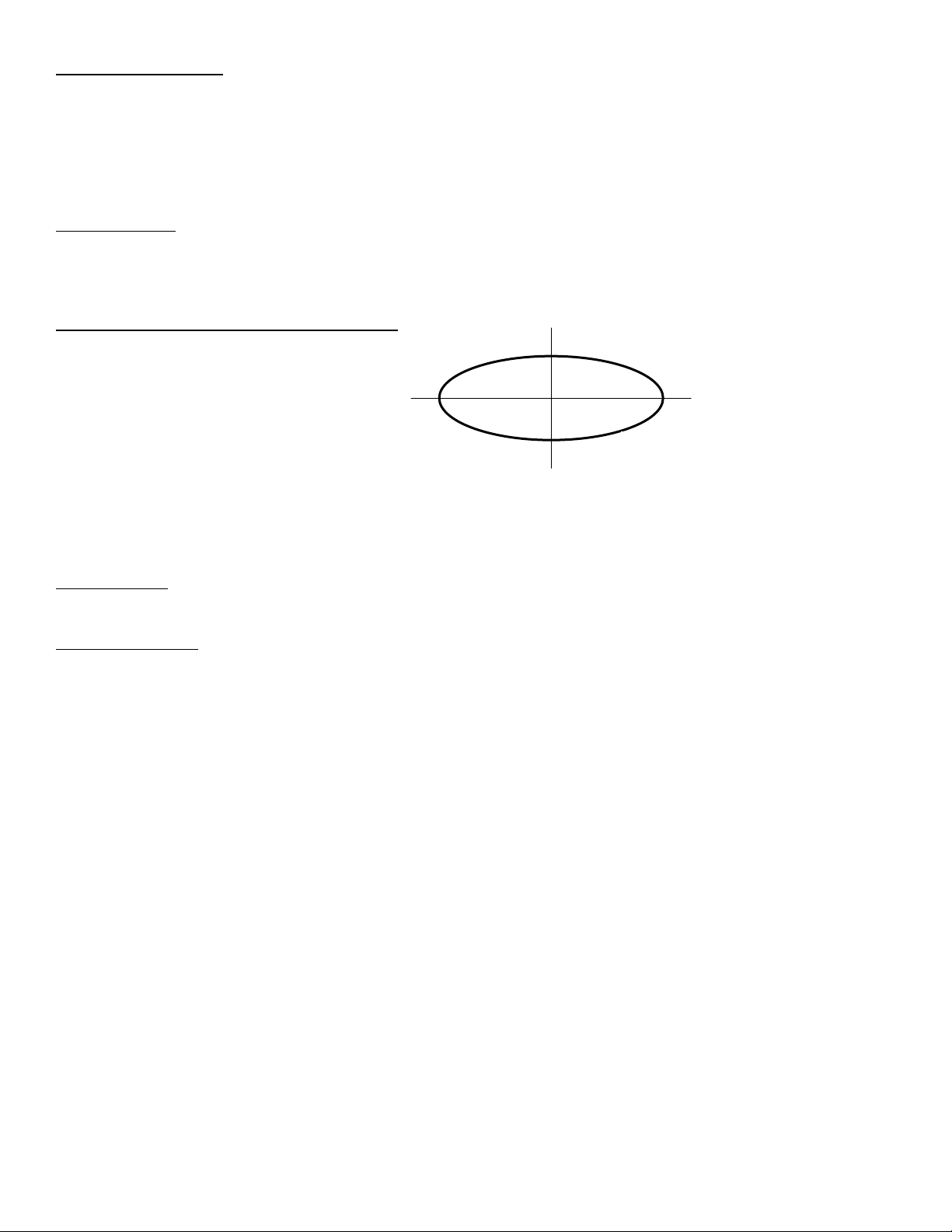
Contour Digitize Notes
Contour digitizing creates an M&G code file with a .cam extension. The structure of the .cam file starts with a
header of comments indicating some of the parameters used when digitizing the contour. Next is the contour itself,
which is outputted as a subprogram. The M&G codes are preceded by an O9800 (start of subprogram) and
followed by an M99 (end of subprogram). The end of the .cam file contains the initial positioning moves and a call
to the contour subprogram (G65 P9800).
Probing direction: When starting the digitizing cycle, choose a starting point where the X travel will contact a point
on the cam on the Y axis. The probe tip will move toward the center line in the X direction until it contacts the
cam, then will move either clockwise or counterclockwise around the cam, depending on which quadrant you
started the cycle (see Table 1).
Table 1 – Probe direction by starting quadrant
X Y Probe travels
- - CW
- + CCW
+ + CW
+ - CCW
- 0 CW
+ 0 CCW
If the probe bypasses a contact point on the Y axis, it will continue moving in the X direction across the center line
until it reaches the patch length limit and faults out.
Canceling a job: Unlike grid or radial digitizing if you cancel a contour operation before it is completed you will
not be able to restart the contour at the point of interruption to continue the cycle. You will need to start over.
Before running a job: Before running a job created by contour digitizing, you will need to add some information to
the file to define any required tool change, cutter compensation and height offset commands.
1. Do a search in the G code for the phrase “Add Comp Here.”
2. Refer to the descriptions of G40, G41 and G42 in Chapter 12.
3. Add the proper G code to the file after the “Add Comp Here” prompt.
4. Save the file, and run your job.
M-Series Operator’s Manual 12/20/13
8-12
Page 72
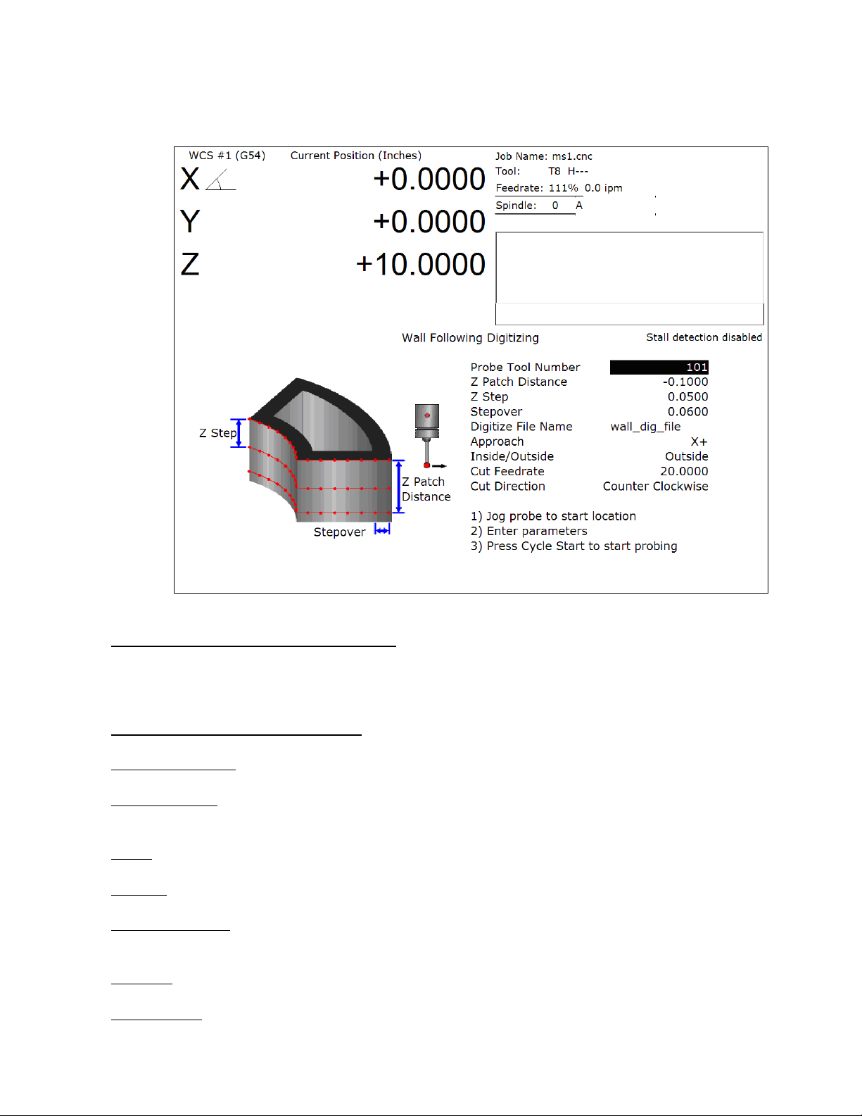
Wall Following Digitizing
(F8 from Digitize Menu)
Setting up a Wall Following Digitizing Run
To set up a digitize run, edit the parameters shown. Jog the probe tip to the XY starting location (inside or outside
of the part to be digitized), and then jog Z to the level of the first digitize pass. Press CYCLE START to start the
digitize run.
Wall Following Digitizing Parameters
Probe Tool Number: The tool number of the probe.
Z Patch Distance: The total Z distance to digitize, incremental from the first pass. Entering a negative value will
cause the routine to step down in the Z. Entering a positive value will cause the routine to step up in the Z.
Z Step: The Z amount to step down per pass.
Stepover: The distance between the digitized points.
Digitize File Name: The base name of the output file in which the digitize data is stored. An extension of .dig will
automatically be appended to the name for replay as a CNC job.
Approach: The direction of the first digitizing move.
Inside/Outside: Starting location of the probe; inside the part or outside.
M-Series Operator’s Manual 12/20/13
8-13
Page 73

Cut Feedrate: The replay feedrate. This is the feedrate that will be output to the file specified by the Digitize File
Name above. This will cause the digitized data to be replayed at this specifed feedrate when the output data is run
as a CNC job.
Cut Direction: The Clockwise or Counter Clockwise direction of the output data. This also defines the direction of
digitze.
Wall Following Digitizing Notes
The output data is uncompensated. Therefore the resultant output data points will be offset by the probe tip’s radius
amount. If you want to run this data as a CNC job and actually do cutting, you must use a cutter that is the same
shape and diameter as the probe tip. An alternative to this is to use a CAD/CAM software package to remove the
probe tip offset and to apply the desired compensation.
M-Series Operator’s Manual 12/20/13
8-14
Page 74
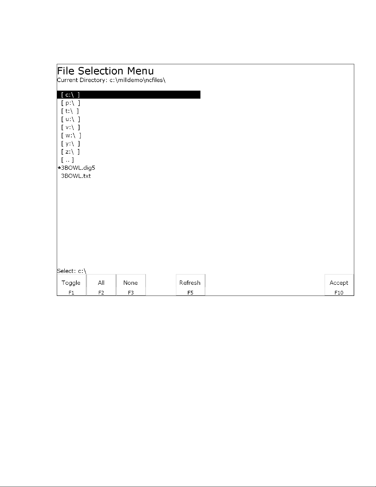
Dig to CAD
(F6 from Digitize Menu)
The Dig to CAD feature of the CNC software is used to export digitized files for use with CAD/CAM
software. The digitized files are converted to point cloud data that is easily readable by most CAD/CAM
systems. Digitized files have either a .DIG or .DIG5 extension. Files with the extension .DIG are created
from the grid or wall following digitizing routines, while .DIG5 files are created from 5-axis digitizing
toolpaths. The resulting point cloud data files will have the same file name as the .DIG and .DIG5 files they
were created from, only they will have a .TXT extension. These files can then be imported into any
CAD/CAM software or viewed with a simple text editor.
In the case of 5-axis CNC controls, where the 4th and 5th axes are rotary axes, parameters 116-119 are used in
conjunction with Dig to CAD to properly position the collected data (see Chapter 14 for more information on
these parameters).
M-Series Operator’s Manual 12/20/13
8-15
Page 75
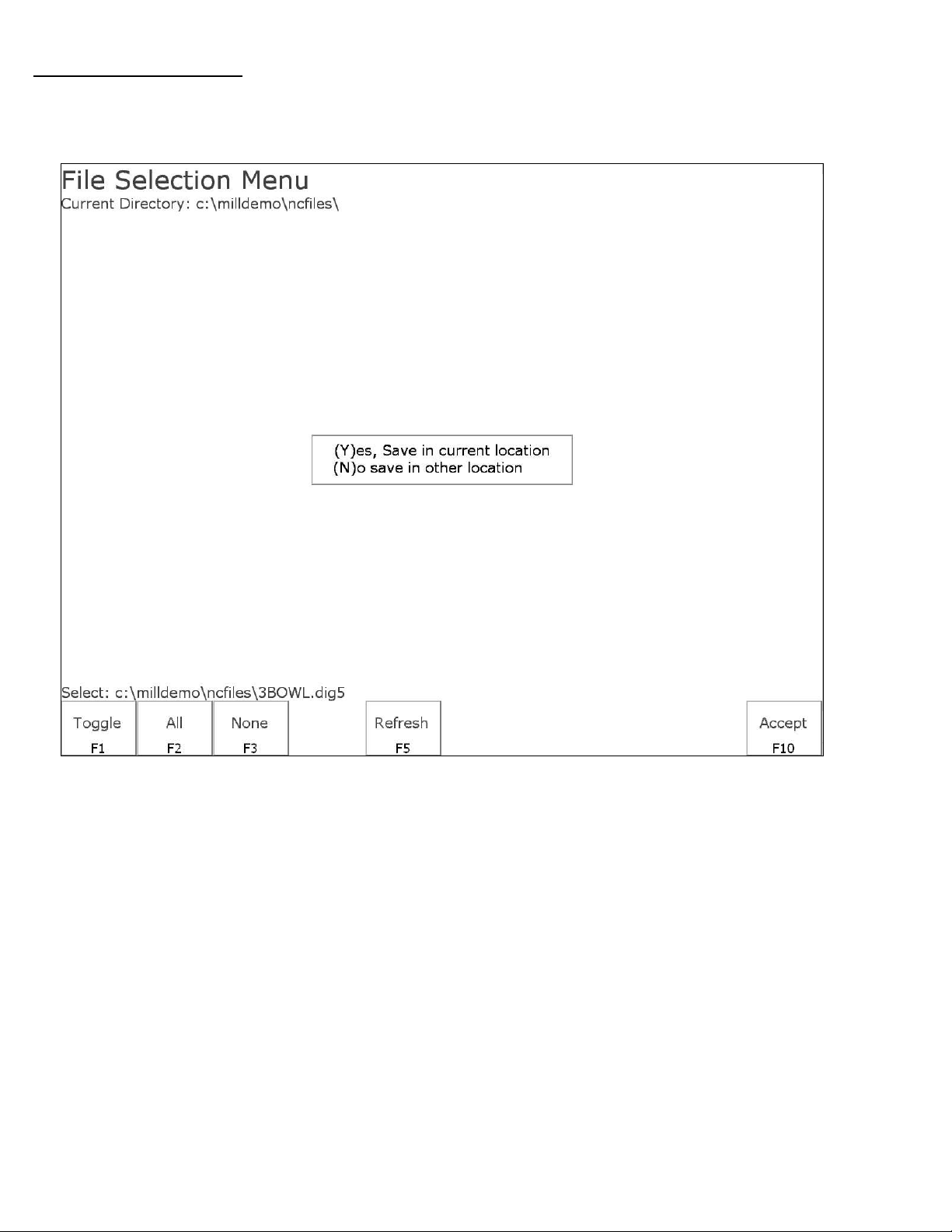
Converting Digitized Data
To export digitized data, first select the files you wish to convert by highlighting the files with the arrow
keys and using either F1-Toggle or the Space bar to select the files. When a file has been selected an
asterisk (*) will appear to the left of the filename. Once you have selected all the files you wish to convert
press F10-Accept.
To convert the files and save them in the same directory as the digitized files press Y. To save the files in a
different location such as a floppy or USB drive press N, navigate to the desired directory using the file
menu, and press F10-Accept to convert and save the files in that location.
M-Series Operator’s Manual 12/20/13
8-16
Page 76
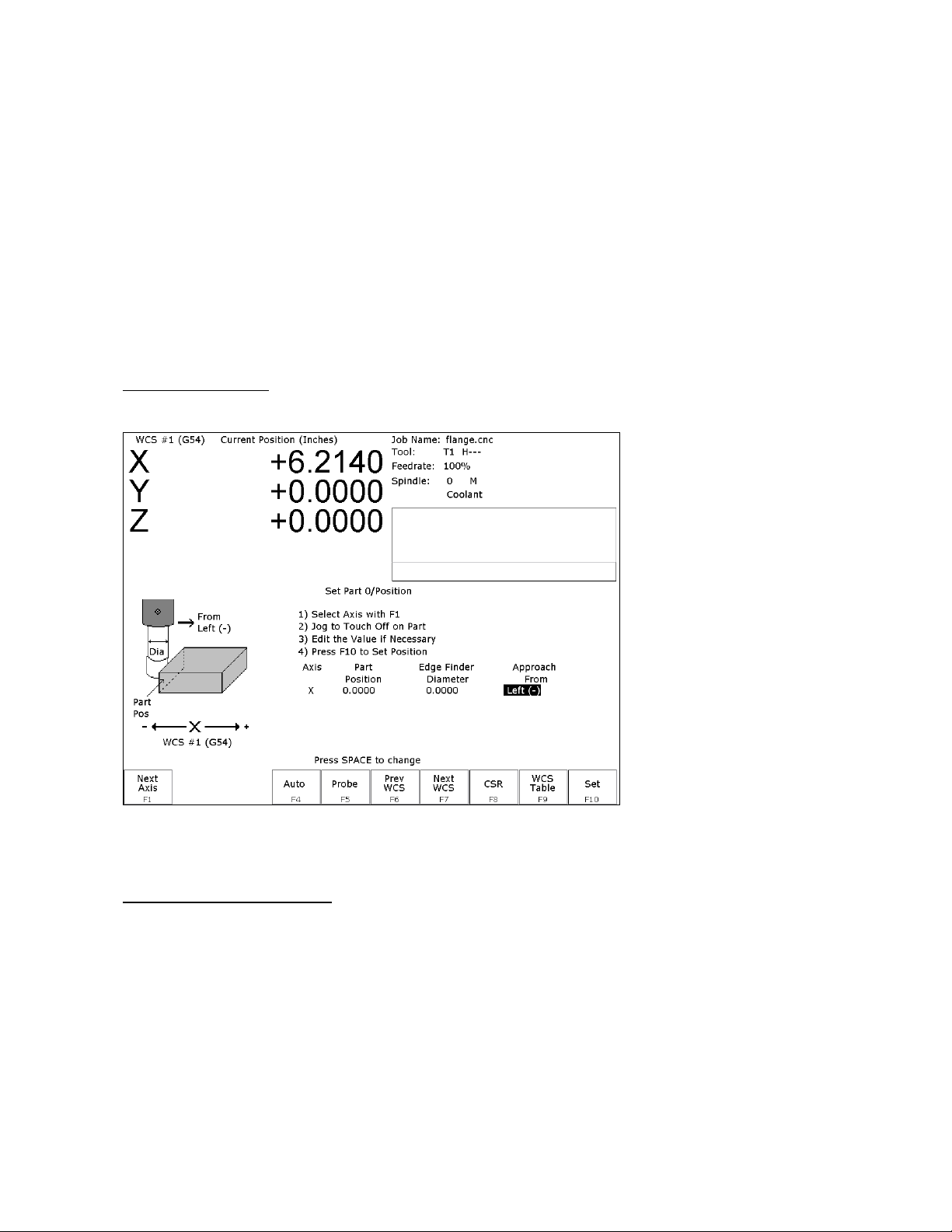
Chapter 9
Probing
Attention!! Refer to the Probe Parameters sections at the end of this chapter before using any
probe.
Part Setup with Probing
Single axis, single surface probing is available on the Set Part 0/Position screen using the F4 - Auto key. This
allows you to probe various surfaces to define the part coordinate system. Multi-axis and multi-surface probing
cycles are available on a separate screen, accessible from Set Part 0/Position with the F5 - Probe key or from F4 -
Probe in the digitize screen. These allow you to locate the center points and corners of differently shaped parts.
Brushless motor note: If you experience excessive vibration on a brushless drive system, use Parameter 10 to select
smooth deceleration in probing moves. See Chapter 14 for more information.
WARNING: Before manually jogging any probe, make sure the machine Feedrate is slow (less than 10
in/min) or damage to the probe may result!
Automatically Setting Part 0
Part zero can be found using the probe. Make sure your probe height and diameter offsets are set for the tool
number you assigned to the probe and that parameter 12 is set to that tool number. The Edge Finder Diameter will
be set automatically.
To set part 0 using the probe:
1. Select the current work coordinate system by pressing F6 – Prev WCS or F7 – Next WCS. Then select the axis
you want to probe by pressing F1 – Next Axis.
2. Manually jog the probe about 1/2 inches away from the surface you wish to define. Make sure the approach
direction to the part is set properly. Probe the selected axis by pressing F4 - Auto. When the surface is found, the
control will assume this point to be the new axis 0.
M-Series Operator’s Manual 12/20/13
9-1
Page 77
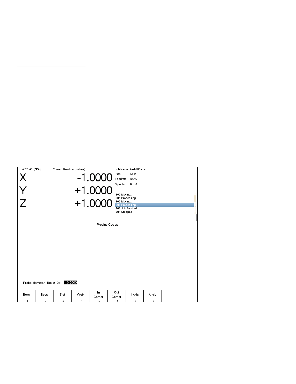
3. If you want this probed surface to be something different than 0, enter the value by the using arrow keys to
highlight Part Position, and then type in the value and press F10 - Set.
Repeat steps 1-3 to set the remaining axes using the probe. Any previously entered Edge Finder Diameter or Tool
Number value will be discarded.
Finding Center/Corner Points
To enter the Probing Cycles screen, press F5 - Probe from the Set Part 0/Position screen. You can locate the center
of a bore, boss, slot, or web. You can also find an inside corner, outside corner, or a single axis. The corner points
don’t even have to be right angles! The Edge Finder Diameter doesn’t need to be entered since these cycles place
the probe directly over the center or corner of the part.
Calibrating the Probe Tip Diameter
You can calibrate the probe tip diameter to compensate for pre-travel (the amount that the probe deflects before it
actually trips). Simply enter a probe tip diameter of zero, probe out a precision bore with a known diameter, and
enter the difference between the reported bore diameter and the found bore diameter as the actual probe tip
diameter.
Probing Cycles
You can enter the Probing Cycles screen from either the Set Part 0/Position screen (F5 - Probe) or the Digitize
menu (F4 - Probe). The Probing Cycles screen is shown below:
The probing cycles will report the location and dimensions, as applicable, of the probed feature in a floating dialog
box. The dimensions are adjusted to compensate for the probe tip diameter, entered in the Offset Library (see
Parameter 12). For your convenience, you can edit the probe diameter on this screen, as long as the Tool Number,
as set in Parameter 12, is not 0. During the probing cycles, the probe will move at speeds specified in Parameters
14 and 15. Refer to the Probe Parameters section later in this chapter for more information.
M-Series Operator’s Manual 12/20/13
9-2
Page 78
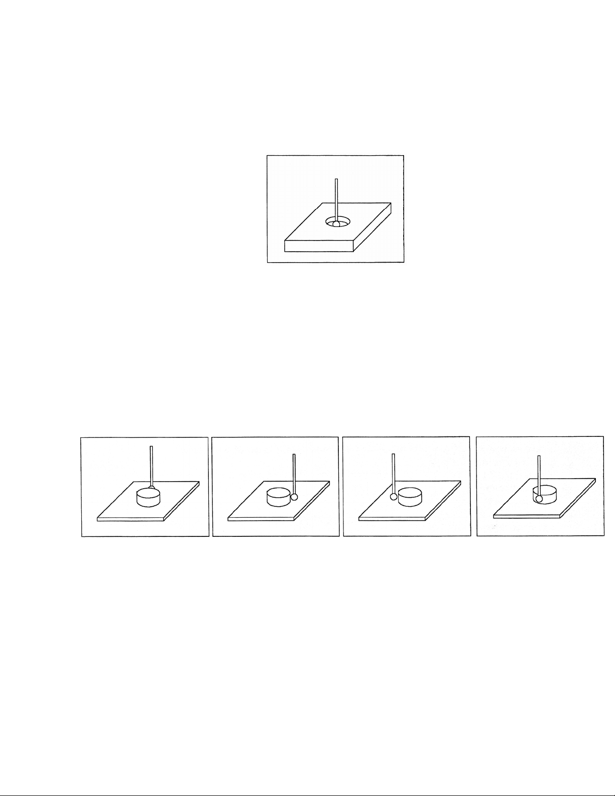
F1 – Bore Press F1 - Bore to enter the Bore screen. A picture similar to the one shown at right will appear,
with instructions. Follow these steps:
1 - Make sure the probe is clear of any obstacles.
2 - Manually jog the probe inside the hole. The probe tip should be just below the top edge of the surface.
3 - Press CYCLE START to start the probing.
At the end of probing, the probe will be positioned at the center of the bore, and the X and Y positions will be
shown on the screen.
Press ESC to return to the Set Part 0/Position screen or digitize screen.
F2 – Boss Press F2 - Boss to enter the Boss screen. A picture similar to the following will appear, with
instructions and two input fields. Follow these steps:
1 - Press F1 - Orient to select the orientation of the probe with respect to the Boss. You will see one of the screens
shown below.
2 - Slowly jog the probe to the approximate orientation as shown in the picture. Be sure to give enough space for
the probe tip to clear any obstacles during the jog.
3 - Enter the approximate Boss diameter.
4 - Highlight the Z clearance amount by pressing the down arrow key. Enter approximate distance (in the Z
direction) the probe must move to lift up over the Boss.
5 - Press CYCLE START to start the probing cycle.
If the Z clearance you entered is too small, the probe will stop and show an error message. Correct the problem by
repeating the previous steps. If the approximate diameter you entered is too small, the probe will bounce by 10
percent of its diameter across the top surface until it either finds the correct edge, the additional distance searched
is equal to Parameter 16, or a travel limit is reached.
Once the probing cycle is complete, the probe will be positioned at the center of the boss at the Z clearance level
entered. Press ESC to return to the Set Part 0/ Position screen or digitize screen.
M-Series Operator’s Manual 12/20/13
9-3
Page 79
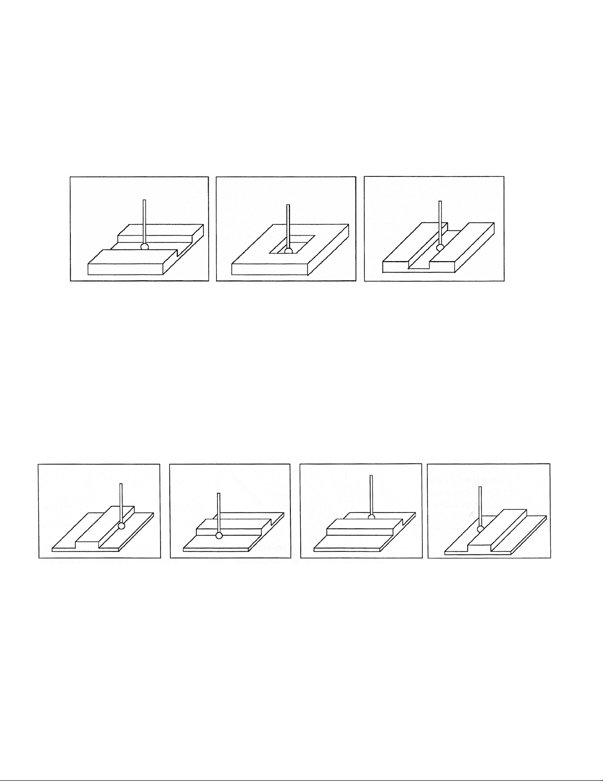
F3 – Slot
instructions:
1 - Press F1 - Orient to select the orientation of the probe with respect to the slot.
2 - Slowly jog the probe to the approximate position shown in the picture. During this jog, make sure you have
enough space between the probe and the part.
3 - Press CYCLE START to begin probing.
Once the cycle is finished, the probe will be located at the center of the slot. Press ESC to return to the Set Part 0 –
Position Screen or digitize screen.
Press F3 - Slot to enter the Slot screen. A picture similar to the ones shown will appear along with
F4 – Web Press F4 - Web to enter the Web screen. A picture similar to the following will appear,
with instructions and two input fields. Follow these steps:
1 - Press F1 - Orient to select the orientation of the probe. You will see one of the screens shown below.
2 - Slowly jog the probe to the approximate position shown in the picture.
During this jog, be sure to give enough space between the probe and the part.
3 - Enter the approximate Web width.
4 - Highlight the Z clearance value using the up or down arrow key. Enter
approximate distance the probe has to travel in order to lift up over the Web.
5 - Press CYCLE START to start the probing cycle. Once the probe has completed
its search, it will automatically position to the centerline of the web.
If the Z clearance you entered is too small, the probe will stop and show an error message. Correct the problem by
repeating the previous steps. If the approximate width you entered is too small, the probe will bounce by 10
percent of its width across the top surface until it either finds the correct edge, the additional distance searched is
equal to Parameter 16, or a travel limit is reached.
Once the probing cycle is complete, the probe will be positioned at the center of the web, at the Z clearance level
entered. Press ESC to return to the Set Part 0/ Position screen or digitize screen.
M-Series Operator’s Manual 12/20/13
9-4
Page 80
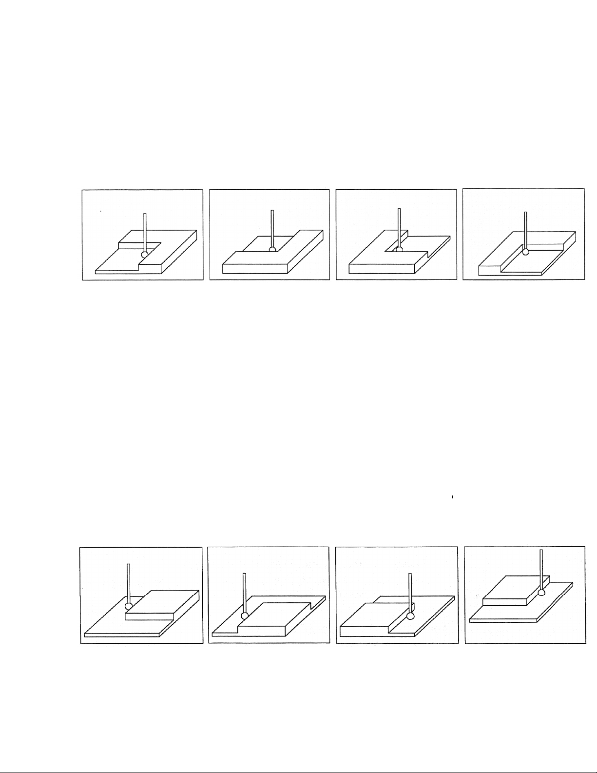
F5 - In Corner (Inside Corner) Press F5 - In Corner to enter the Inside Corner screen. One of the
pictures will appear with instructions. This cycle is similar to that of a slot cycle; the main
difference is that you need to enter a clearance amount.
1 - Press F1 Orient and the screen will cycle through one of the probe orientations shown here.
2 - Enter the clearance Amount. This is an approximate distance (in the Z direction) the probe must move to clear
the corner
3 - If the corner is rounded, jog the probe far enough away for it to miss the curved area during the probing cycle (at
least twice the corner radius).
4 - Press CYCLE START to start the probing cycle.
At the end of the probing cycle, the probe will be positioned above the corner at the Z clearance level entered. Press
ESC to return to the Set Part 0/ Position screen or digitize screen.
F6 - Out Corner (Outside Corner) Press F6 – Out Corner to enter the Outside Corner screen. A picture
similar to the following will appear, with instructions and two input fields.
Follow these steps:
1 - Press F1 - Orient to select the orientation of the probe with respect to the Corner. You will see one of the
pictures shown.
2 - Press F2 - Side to select which side of the corner the probe will be positioned near. You will see the screen
change.
3 - Slowly jog the probe to the approximate position as shown in the picture. Be sure to give enough probe
clearance.
4 - Select the Z clearance field using the arrow keys. Enter the approximate distance the probe has to travel in order
to lift up over the corner.
5 - Select the Distance to Corner amount using the up or down arrow keys. Enter the approximate distance from the
corner the probe is along the X or Y axis.
6 - Press CYCLE START to start the probing cycle.
Once the probe has completed its search, it will be positioned above the corner at the Z clearance you specified.
Press ESC to return to the Set Part 0/ Position screen or digitize screen.
M-Series Operator’s Manual 12/20/13
9-5
Page 81
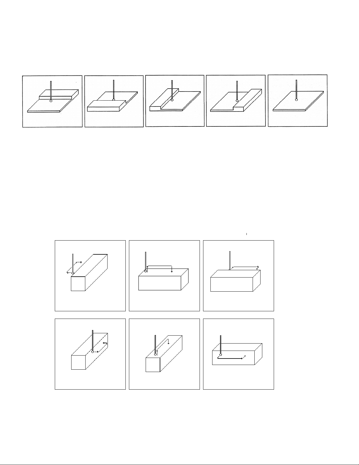
F7 - 1 Axis (Single Axis) Press F7 - 1 Axis to enter the Single Axis screen. Follow these steps:
1 - Press F1 - Orient to select the orientation of the probe. You will see one of the screens shown below.
2 - Slowly jog the probe to the approximate position as shown in the picture. Be sure to give enough probe
clearance.
3 - Press CYCLE START to start the probing cycle.
Once the probing cycle is complete, the probe will move away from the surface by the amount in Parameter 13. The
probed position will be shown on screen. Press ESC to return to the Set Part 0/ Position screen or digitize screen.
F8 – Angle – Use this feature to measure an angle from based on 2 probed points.
Follow these steps:
1 - Press F1 - Orient to select how the angle is to be measured.
2 - Slowly jog the probe to the first position as shown in the picture. Be sure to give enough probe clearance.
3 - Select Auto or Jog between points.
4 - Enter the distance to second point.
5 - Enter a clearance amount away from the surface.
6 - Press CYCLE START to start the probing cycle.
M-Series Operator’s Manual 12/20/13
9-6
Page 82

Probe / TT-1 Parameters
Various probing parameters can be set on the Machine Parameters screen (see Chapter 14). Make sure you enter
these parameters before you begin using the probe and/or TT-1. If these parameters are not entered properly,
damage to the probe or TT-1 may result.
Probe Type (Parameter 155) – This specifies the probe type being used. This needs to be set to 0 if you are using
a standard Mechanical probe.
Probe PLC Input Number and Contact State (Parameter 11) - A single value, +/-1 through 240. A positive
number indicates Closed on contact; a negative number indicates Open on contact.
TT1 PLC input number (Parameter 44) - This parameter is the input number that the TT1 is wired into on the
PLC. If a shared PLC input is used for both the TT1 and the probe, then the value can be left at zero or set to the
same value as parameter 11.
Probe Tool Number (Parameter 12) - A single value, 0 through 200, used to look up the length offset and tip
diameter of the probe in the Offset Library.
Recovery Distance* (Parameter 13) – The additional distance the probe moves off of a surface after contact is
broken, before attempting to traverse parallel to the surface.
Fast Probing Rate* (Parameter 14) - Used for positioning moves and initial surface detection, this parameter is
determined by machine response and permitted probe deflection as well as desired tolerance. The default setting is
25 inches/min.
Slow Probing Rate* (Parameter 15) - Used for final measuring moves, this parameter is determined by a
speed/accuracy tradeoff. The default setting is 3.5 inches/min.
Maximum Probing Distance (Parameter 16) - The maximum distance that a probing cycle "searches" for a
surface in a given direction if no travel limits have been entered. The default is 10 inches. A larger value should
be entered for the hole and slot cycles if you are measuring very large features.
Detector Location Return Point (Parameter 17) - A Zero (0) indicates that tool measurement will take place at
the current position, a 1 or 2 indicates the number of the G30 reference point to use which specifies the X, Y
location of the TT1 (WCS Configuration).
*Mechanical type probe only. Please see the DSP type probe section below for differences.
M-Series Operator’s Manual 12/20/13
9-7
Page 83

DSP Probe Parameters
When using a DSP type probe (such as DP-4D), a few of the probing parameters have a slightly different behavior
than described above. These differences are noted below:
Probe Type (Parameter 155) – This specifies the probe type being used. This needs to be set to 1 for a DP-4D
probe or set to 2 for a DP-7 probe.
Repeatability tolerance for probing and radial digitizing (Parameter 151) – used for DP-4 probes. Must be set
to 0 for DSP probes.
Grid digitize prediction minimum Z pullback (Parameter 121) – set to 0.035 for DSP use.
Recovery Distance (Parameter 13) – Works as described above but additionally it used as the distance to retract
for a retry after a failed window (does not apply to M115/116/125/126 moves) (Default for DSP is 0.05). Note: If
probing small bores this parameter may need to be reduced accordingly.
Fast Probing Rate (Parameter 14) – When using a DSP type probe, this is actually the rate at which the probe
will move “in-between” actual probing moves. For instance, if you were probing a boss, this is the rate at which
the probe will travel for the following moves:
1. When retracting from the surface after a point has been probed.
2. When retracting to the Z clearance position.
3. Rate at which it will traverse across the diameter of the boss at the Z clearance height.
4. Plunge rate to get to probing depth.
Note: When measuring a TOOL with the TT1, the behavior is identical to that listed above.
Slow Probing Rate (Parameter 15) – Used only when measuring a TOOL with the TT-1.
Additional Probe Parameters for DP-7
For the DP-7 probe (parameter 155 = 2), the following additional parameters are utilized:
DP-7 Pullback Distance (Parameter 392) – This sets the distance the probe moves off from the surface after a
probing move.
DP-7 Pullback Feedrate (Parameter 393) – This sets the feedrate for the pullback move.
DP-7 Measuring Feedrate (Parameter 394) – This sets the feedrate for the slow measuring move.
M-Series Operator’s Manual 12/20/13
9-8
Page 84
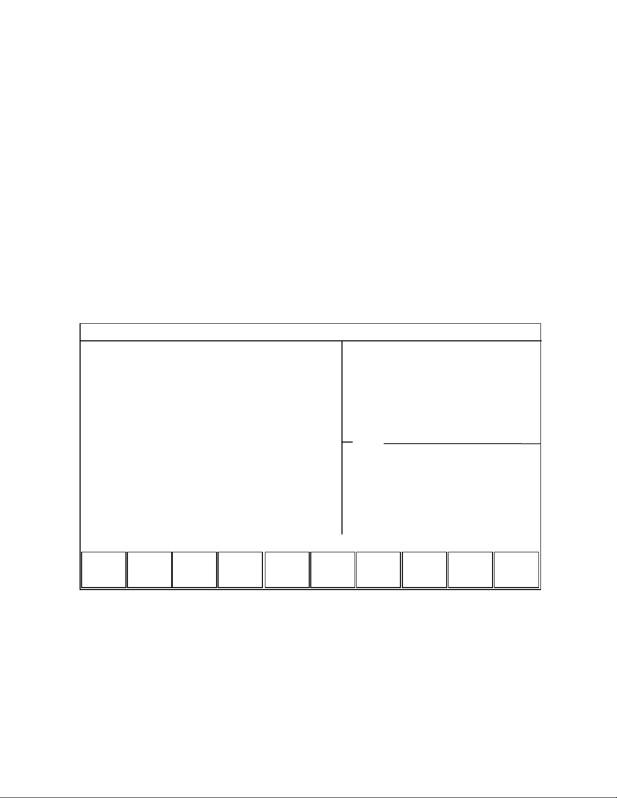
Chapter 10
Intercon Mill
Intercon Mill Intercon Mill
Intercon Mill
Current Part: Flange.icn
Current Part: Flange.icn Current Part: Flange.icn
Current Part: Flange.icn
FFFF
1111
FFFF
2222
Copy
CopyCopy
Copy
FFFF
7777
FFFF
5555
FFFF
3333
FFFF
4444
FFFF
6666
FFFF
8888
FFFF
10
1010
10
FFFF
9999
;Motor Flange
;Motor Flange;Motor Flange
;Motor Flange
Home
Home Home
Home
0.0000
0.00000.0000
0.0000
0.0000
0.00000.0000
0.0000
0001
00010001
0001
Operation End
Operation End Operation End
Operation End
Status
StatusStatus
Status
Intercon Software
Introduction
Intercon (Interactive Conversational) software allows you to quickly create a part program right at the control without
having to be a G-code expert. Intercon will prompt you to enter values from your print that describes the geometry of
the part. Intercon will display graphics of the part as you are creating it, helping you quickly proceed through part
programming. Intercon can then generate a G-code program from the geometric information you have entered.
You can purchase an offline version of the Intercon software for use on your desktop PC. You will need to purchase a
hardware key, which will allow the offline version to run. Simply plug the key into the computer, install the required
drivers, and run it.
Intercon Main Screen
When you access Intercon through the F5 - CAM option in the CNC software Main screen, the part program will be
displayed if the current job loaded in CNC software had an associated Intercon program. If the job file in the CNC
software did not have an associated Intercon program, the F1 - File menu will be displayed to load or create a file.
Modify
Modify
ModifyModify
0.0000
0.0000
0.00000.0000
1.0607
1.0607
1.06071.0607
3.2500
3.2500
3.25003.2500
3.2500
3.2500
3.25003.2500
Insert
Insert
InsertInsert
0.1000
0.1000
0.10000.1000
0.1000
0.1000
0.10000.1000
0.1000
0.1000
0.10000.1000
Home
Home
Home Home
Paste
Paste
PastePaste
Copy
Copy
CopyCopy
Menus..
Menus..
Menus..Menus..
Graph
Graph
GraphGraph
Setup
Setup
SetupSetup
Post
Post
PostPost
0.0000
0.0000
0.00000.0000
1.6070
1.6070
1.60701.6070
4.1250
4.1250
4.12504.1250
4.1250
4.1250
4.12504.1250
Cut
Cut
CutCut
# Type X Y Z
# Type X Y Z
# Type X Y Z # Type X Y Z
0002
0002
00020002
0003
0003
00030003
0004
0004
00040004
0005
0005
00050005
0006
0006
00060006
Tool #1
Tool #1
Tool #1Tool #1
Circ Poc
Circ Poc
Circ PocCirc Poc
Drill BHC
Drill BHC
Drill BHCDrill BHC
Frame
Frame
FrameFrame
End Prog
End Prog
End ProgEnd Prog
File
File
FileFile
When the part program is displayed, different operations can be navigated and highlighted for additional actions by
using the arrow keys, and the HOME, END, PAGE UP and PAGE DOWN keys.
M-Series Operator’s Manual 12/20/2013 10-1
Page 85
File Menu (Intercon Main Screen ► F1 – File)
Intercon Mill
Intercon Mill Intercon Mill
Intercon Mill
Current Part: Flange.icn
Current Part: Flange.icn Current Part: Flange.icn
Current Part: Flange.icn
FFFF
1111
FFFF
2222
FFFF
5555
FFFF
3333
As
As As
As
F4
F4 F4
F4
Details
DetailsDetails
Details
FFFF
9999
Intercon File Menu
Intercon File Menu Intercon File Menu
Intercon File Menu
[ a:
[ a:[ a:
[ a:
\\\\
]]]]
Drive
DriveDrive
Drive
Sandisk
SandiskSandisk
Sandisk
File Programmer Description Date Modified
File Programmer Description Date Modified File Programmer Description Date Modified
File Programmer Description Date Modified
John Q. Public
John Q. PublicJohn Q. Public
John Q. Public
06
0606
06
----
Oct
OctOct
Oct
----
2006
20062006
2006
Directory: c:
Directory: c:Directory: c:
Directory: c:
\\\\
intercon
intercon intercon
intercon
Floppy
Floppy Floppy
Floppy
FFFF
2222
Details
DetailsDetails
Details
FFFF
3333
Show
ShowShow
Show
FFFF
4444
Date/
Date/Date/
Date/
FFFF
5555
FFFF
6666
Help
HelpHelp
Help
FFFF
7777
FFFF
9999
F1
F1F1
F1
0000
G code
G code G code
G code
F1
F1F1
F1
Load file from CNC hard drive
Load file from CNC hard driveLoad file from CNC hard drive
Load file from CNC hard drive
c:
c:c:
c:
\\\\
intercon
interconintercon
intercon
Use arrow keys to select file to load and press F10 to Accept.
Use arrow keys to select file to load and press F10 to Accept.Use arrow keys to select file to load and press F10 to Accept.
Use arrow keys to select file to load and press F10 to Accept.
Job
Job Job
Job
to
toto
to
load? bracket.cnc
load? bracket.cnc load? bracket.cnc
load? bracket.cnc
[..]
[..][..]
[..]
Parent directory
Parent directoryParent directory
Parent directory
File Programmer
File Programmer File Programmer
File Programmer
Description Date Modified
Description Date Modified Description Date Modified
Description Date Modified
06
0606
06
----
Oct
OctOct
Oct
----
2006
20062006
2006
F1 – File
Choosing F1 - File will display the screen below. Intercon stores part programs with an extension of
.icn. For example, if you choose to name your new part program flange, Intercon will save the program as flange.icn.
ICN files are only readable by Intercon.
[ c:
[ c:\\\\]]]]
[ c:[ c:
[ d:
[ d:\\\\]]]]
[ d:[ d:
[ j:
[ j:\\\\]]]]
[ j:[ j:
[..]
[..]
[..][..]
flange
flange
flangeflange
helix
helix
helixhelix
irreg
irreg
irregirreg
lineclr
lineclr
lineclrlineclr
thread
thread
threadthread
__oscp__
__oscp__
__oscp____oscp__
__osda__
__osda__
__osda____osda__
__osdb__
__osdb__
__osdb____osdb__
__osdr__
__osdr__
__osdr____osdr__
__osfa__
__osfa__
__osfa____osfa__
__osfr__
__osfr__
__osfr____osfr__
__osrp__
__osrp__
__osrp____osrp__
John Q. Pu
John Q. Public
John Q. PuJohn Q. Pu
John Q. Public
John Q. Public
John Q. PublicJohn Q. Public
--
--
---John Q. Public
John Q. Public
John Q. PublicJohn Q. Public
One Shot Circ Pocket
One Shot Circ Pocket
One Shot Circ PocketOne Shot Circ Pocket
One Shot Drill Array
One Shot Drill Array
One Shot Drill ArrayOne Shot Drill Array
One Shot Drill BHC
One Shot Drill BHC
One Shot Drill BHCOne Shot Drill BHC
One Shot Drill Cycle
One Shot Drill Cycle
One Shot Drill CycleOne Shot Drill Cycle
One Shot Face
One Shot Face
One Shot FaceOne Shot Face
One Shot Frame
One Shot Frame
One Shot FrameOne Shot Frame
One Shot Rect Pocket
One Shot Rect Pocket
One Shot Rect PocketOne Shot Rect Pocket
blic
blicblic
Drive
Drive
DriveDrive
Drive
Drive
DriveDrive
Drive
Drive
DriveDrive
Parent directory
Parent directory
Parent directoryParent directory
Demo Flange Part
Demo Flange Part
Demo Flange PartDemo Flange Part
Demo Helix Part
Demo Helix Part
Demo Helix PartDemo Helix Part
Demo Pocket Cleanout
Demo Pocket Cleanout
Demo Pocket CleanoutDemo Pocket Cleanout
--
--
---Demo Thread
Demo Thread
Demo ThreadDemo Thread
* DO NOT MODIFY *
* DO NOT MODIFY *
* DO NOT MODIFY * * DO NOT MODIFY *
* DO NOT MODIFY *
* DO NOT MODIFY *
* DO NOT MODIFY * * DO NOT MODIFY *
* DO NOT MODIFY *
* DO NOT MODIFY *
* DO NOT MODIFY * * DO NOT MODIFY *
* DO NOT MODIFY *
* DO NOT MODIFY *
* DO NOT MODIFY * * DO NOT MODIFY *
* DO NOT MODIFY *
* DO NOT MODIFY *
* DO NOT MODIFY * * DO NOT MODIFY *
* DO N
* DO NOT MODIFY *
* DO N * DO N
* DO NOT MODIFY *
* DO NOT MODIFY *
* DO NOT MODIFY * * DO NOT MODIFY *
OT MODIFY *
OT MODIFY *OT MODIFY *
06
06----Oct
Oct----2006
0606
OctOct
06
06----Oct
Oct----2006
0606
OctOct
19
19----Nov
Nov----2006
1919
NovNov
06
06----Oct
Oct----2006
0606
OctOct
06
06----Oct
Oct----2006
0606
OctOct
06
06----Oct
Oct----2006
0606
OctOct
06
06----Oct
Oct----2006
0606
OctOct
06
06----Oct
Oct----2006
0606
OctOct
06
06----Oct
Oct----2006
0606
OctOct
06
06----Oct
Oct----2006
0606
OctOct
06
06----Oct
Oct----2006
0606
OctOct
2006
20062006
2006
20062006
2006
20062006
2006
20062006
2006
20062006
2006
20062006
2006
20062006
2006
20062006
2006
20062006
2006
20062006
2006
20062006
New
New
Load
NewNew
Load
LoadLoad
Save
Save
SaveSave
Save
Save
Save Save
Delete
Delete
DeleteDelete
On/Off
On/Off
On/OffOn/Off
F1 – File ► F1 – New
To program a new part, choose F1 – New. A prompt will be displayed where the name
of the new program can be typed, followed by the F10 - Accept or ENTER key to accept the new name can be
entered. You can enter who the programmer is, a program description, the units of measure and the date.
Load Menu (Intercon Main Screen ► F1 – File ► F2 – Load)
F1 – File ► F2 – Load
M-Series Operator’s Manual 12/20/2013 10-2
flange
flange
flangeflange
helix
helix
helixhelix
irreg
irreg
irregirreg
thread
thread
threadthread
__oscp__
__oscp__
__oscp____oscp__
__osda__
__osda__
__osda____osda__
_____osdb__
_osdb__
_osdb___osdb__
/ICN
/ICN
/ICN/ICN
////USB/
When you press F2 - Load, the screen below is displayed. (Shown with details “ON”)
John Q. Public
John Q. Public
USB/LAN
LAN
USB/USB/
LANLAN
John Q. PublicJohn Q. Public
John Q. Public
John Q. Public
John Q. PublicJohn Q. Public
John Q. Public
John Q. Public
John Q. PublicJohn Q. Public
One Shot Circ Pocket
One Shot Circ Pocket
One Shot Circ PocketOne Shot Circ Pocket
One Shot Drill Array
One Shot Drill Array
One Shot Drill ArrayOne Shot Drill Array
One Shot Drill BHC
One Shot Drill BHC
One Shot Drill BHCOne Shot Drill BHC
One Shot Drill Cycle
One Shot Drill Cycle
One Shot Drill CycleOne Shot Drill Cycle
On/Off
On/Off
On/OffOn/Off
Recent
Recent
RecentRecent
Demo Flange Part
Demo Flange Part
Demo Flange PartDemo Flange Part
Demo Helix Part
Demo Helix Part
Demo Helix PartDemo Helix Part
Demo Pocket Cleanout
Demo Pocket Cleanout
Demo Pocket CleanoutDemo Pocket Cleanout
Demo Thread
Demo Thread
Demo ThreadDemo Thread
* DO NOT MODIFY *
* DO NOT MODIFY *
* DO NOT MODIFY * * DO NOT MODIFY *
* DO NOT MODIFY *
* DO NOT MODIFY *
* DO NOT MODIFY * * DO NOT MODIFY *
* DO NOT MODIFY *
* DO NOT MODIFY *
* DO NOT MODIFY * * DO NOT MODIFY *
Edit
Edit
Alpha
Alpha
AlphaAlpha
EditEdit
On
On////Off
Off
OnOn
OffOff
06
06----Oct
0606
00006666----Oct
19
19----Nov
1919
06
06----Oct
0606
06
06----Oct
0606
06
06----Oct
0606
06
06----Oct
0606
Advanced
Advanced
Graph
Graph
Graph Graph
AdvancedAdvanced
Oct----2006
2006
OctOct
20062006
Oct----2006
2006
OctOct
20062006
Nov----2006
2006
NovNov
20062006
Oct----2006
2006
OctOct
20062006
Oct----2006
2006
OctOct
20062006
Oct----2006
2006
OctOct
20062006
Oct----2006
2006
OctOct
20062006
Accept
Accept
AcceptAccept
Page 86

To navigate the files in the load menu, use the arrow keys to move the cursor around and highlight the file to be
loaded. The HOME, END, PAGE UP and PAGE DOWN keys can be used to navigate the list of files. Names that
are bracketed, for example [..], are the names of directories in the current directory, which is displayed at the top of the
screen.
It is also possible to start typing the name of the program to be loaded. When typing has started, the characters appear
in the “File to load:” prompt above the function keys. Different drives and directories can be accessed by typing in the
path at the “File to load:” prompt, or by pressing F10 or ENTER on a bracketed directory name. When loading a new
file, a prompt will be displayed asking whether to save the existing file if there was one.
Additional Load Menu options are detailed below:
F1 – G code/ICN Allows user to toggle the view between the Intercon files present in either c:\intercon or
c:\cncm\ncfiles.
F2 – Floppy USB/LAN Provides options for loading Intercon files from USB devices, floppy and LAN drives.
F3 – Details On/Off The F3-Details On/Off option changes the format of the display such that each file or directory
is on a separate line and there are columns displayed for Programmer, Description, and Date Modified, i.e., the
information that is contained in the program header operation.
F4 – Show recent Use the F4–Show Recent option to show the 15 most recently loaded Intercon and g-code files. It
is important to remember that even though g-code files are displayed on this screen, ONLY Intercon files should be
loaded from this screen. WARNING!!! Attempting to load a g-code file from the “Show Recent” screen will cause an
error which will discard the current Intercon program. All unsaved changes will be lost. If you should accidently load
a g-code file, press escape to return to the main Intercon menu.
F5 – Date/Alpha Use F5-Date/Alpha to view files either alphabetically or by date modified. By default, programs
are listed in ascending alphabetical order.
F6 – Edit Opens the selected file in Intercon for editing.
F7 – Help On/Off Displays on screen help for the load menus.
F8 – Graph Graphs the selected file.
F9 – Advanced Displays file menu in a comprehensive “all in one” format similar to Windows Explorer
File Menu (Intercon Main Screen ► F1 – File, continued from pg 10-2)
F1 – File ► F3 – Save
under the specified name.
F1 – File ► F4 - Save As
new name into the “Save part as:” prompt that appears above the function keys. If the new name already exists, a
prompt will be displayed as a warning and will give the option to overwrite the existing file or return to enter a
different name.
F1 – File ► F5 – Delete
as in the F2 - Load option where you can be to navigate the files. A yes/no prompt will appear after accepting a file
for deletion for final confirmation.
M-Series Operator’s Manual 12/20/2013 10-3
Press F3 - Save to save the current part program. The current program will be saved
Press F4 – Save As to save the current program with a different name. Type the
Press F5 - Delete to delete a file. After F5 - Delete is pressed, the screen will appear
Page 87

F1 – File ► F9 - Details on/off
file or directory is on a separate line and there are columns displayed for Programmer, Description, and Date Modified,
i.e., the information that is contained in the program header operation.
The F9 - Details On/Off changes the format of the display such that each
Intercon Main Screen (continued from pg 10-1)
F2 – Modify
to be modified. When an operation is modified, the fields for that operation are displayed on the right hand side.
When modifying an operation, the PAGE UP and PAGE DOWN keys can be used to move up and down through the
Intercon operations listed on the left hand side of the screen.
F3 – Insert
unless the highlighted operation is the first operation in which case the inserted operation will be inserted as the second
operation. For more information on the operations see Insert Operations later in this chapter.
F4 – Cut
cut is placed onto the clipboard stack.
F5 – Paste
current program line that is before the highlighted operation. The number of operations that are currently in the
clipboard stack are indicated by the number in the Paste key. As long as you stay in Intercon, the clipboard stack will
remain intact. You may cut and copy operations from one program and paste them into a different program.
F6 – Copy
cursor to the next operation.
F7 – Copy Menus…
F1 - Copy Menu Allows a range of operations to be copied. Specify the Start Block, End Block, and
Destination in the prompts that appear in the Copy Menu. The range of operations is copied into a location that
precedes the destination block.
F2 - Move Menu Allows a range of operations to be moved. Specify the Start Block, End Block, and
Destination in the prompts that appear in the Move Menu. The range of operations is moved into a location that
precedes the destination block.
F9 - Clear Clipbrd Removes all operations in the clipboard stack.
F8 – Graph
produced if the current program were translated into G-codes and graphed from the CNC software. Canned drilling
cycles are shown in gray. Rapid traverse movements are shown in red. Feedrate movements are shown in yellow and
cutter compensated moves are in gray.
Choosing F2 - Modify from the Intercon main menu will allow the currently highlighted operation
Choosing F3 - Insert will insert a new operation before the operation that is currently highlighted,
Choosing F4 - Cut will cut (remove) the highlighted operation from the program. The operation that is
Choosing F5-Paste will paste the last operation that was cut or copied into the clipboard stack into the
Choosing F6 - Copy will copy the highlighted operation into the clipboard stack and advance the
Choosing F7 - Copy Menus… will display these additional options:
Choosing F8 - Graph will graph the current program. The graph is the same as what would be
M-Series Operator’s Manual 12/20/2013 10-4
Page 88
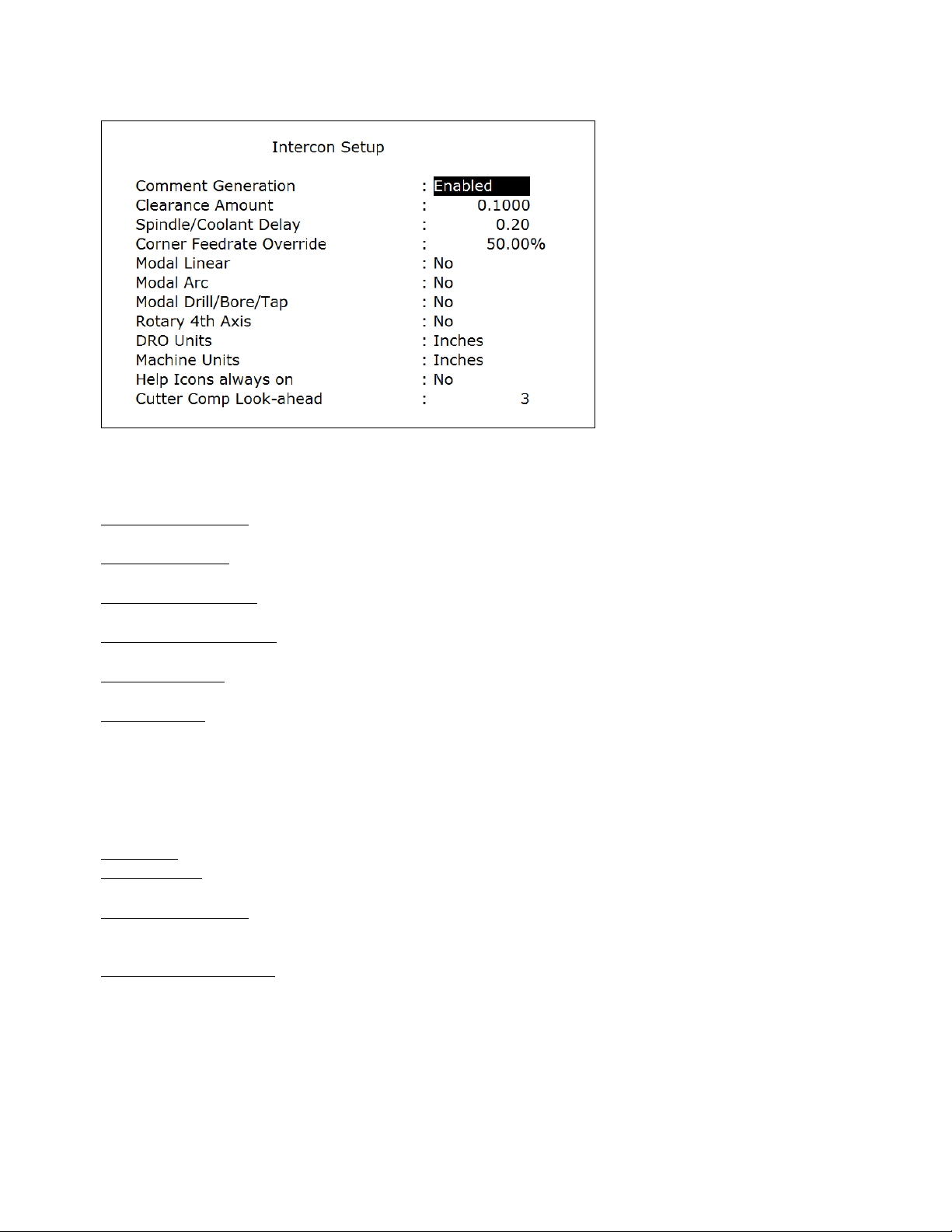
F9 – Setup
appears as below.
Choosing F9 - Setup will display the Setup menu where certain options can be set. The Setup menu
Use the up and down arrow keys to move. Clearance Amount, Spindle/Coolant Delay, and Corner Feedrate Override
require a value to be typed in. The other fields have fixed values that may be toggled by using the F1 - Toggle key.
Comment Generation: When this field is set to Enabled, Intercon will put a comment describing the operation type
before each block. Disabling Comment Generation will make the CNC files generated by Intercon smaller.
Clearance Amount: This is the distance that Intercon raises the Z-axis above the programmed surface height in
pockets, facing and frame mills when traveling across the work piece.
Spindle/Coolant Delay: Set this delay to the time in seconds you want Intercon to wait for the spindle to get up to
speed and the coolant to begin flowing.
Corner Feedrate Override: This is the percent feedrate that will be used in the corners of rectangular pockets and inside
frame mills. The default value is 50%.
Modal Operations: These options specify whether to automatically insert the same operation after the first has been
accepted. Once modal insert mode has begun, press ESC to insert a different operation.
Rotary 4th Axis: This option specifies whether or not 4th axis movement fields appear in Linear and Rapid moves and
whether or not the Intercon program will post 4th axis movement. This option affects the value in the 4th axis
configuration only (parameter 94). Note that although Intercon is restricted to working with 1 rotary axis at a time, it
can be directed to utilize the 5th axis as its rotary axis instead of the 4th. To make Intercon to utilize the 5th axis as its
rotary axis instead of the 4th axis, the 4th axis configuration (parameter 94) must have its rotary property turned off (bit
0 = 0) and the 5th axis configuration (parameter 166) must have its rotary property turned on (bit 0 = 1). See chapter
14 for details about parameters 94 and 166.
DRO Units: Specifies the Units used for the DRO. It affects the corresponding field in the Control Configuration.
Machine Units: Specifies the Units used for machining. It affects the corresponding field in the Control Configuration
of the CNC software. The posted G-code will contain a G20 for Inches mode and a G21 for Metric mode.
Help Icons always on: Toggle between yes or no. Selecting “yes” means that help information will always be
displayed when editing operations. “No” means that you will have to press a key to get help. Whether set to “yes” or
“no”, the help screens can always be toggled on or off by pressing the F5 - Help key when editing an operation.
Cutter Comp Look-ahead: This sets the number of segments that can be parsed ahead when Cutter Comp is turned on.
F10 – Post
into G-codes. When the posting process is completed, Intercon is exited. The Intercon program is also saved as part of
the posting.
Choosing F10 - Post will post the current program. Posting is the process of converting the operations
M-Series Operator’s Manual 12/20/2013 10-5
Page 89
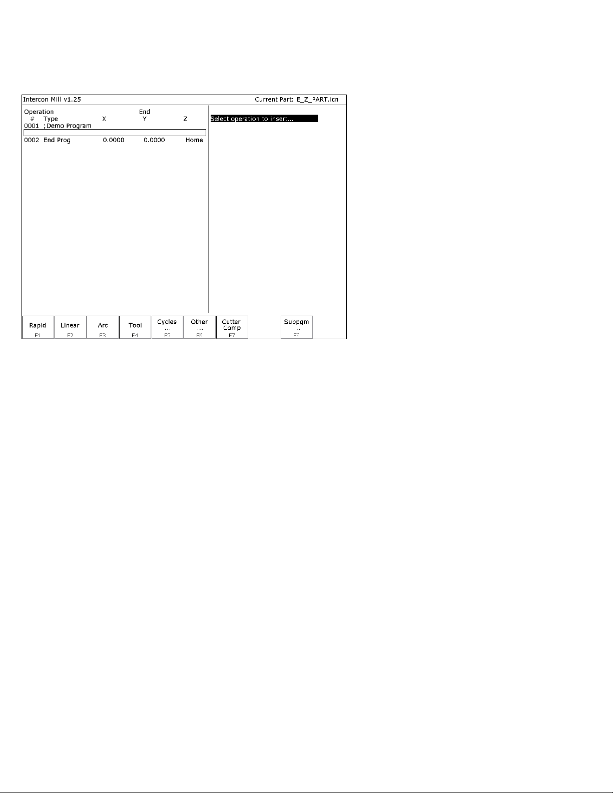
Insert Operation (Intercon Main Screen ► F3 – Insert)
When you press F3 - Insert, or when you choose New Part from the Main Screen, you will see the Insert screen:
The new operation will be inserted right before the currently highlighted one. The operation types that you can insert
are listed across the bottom of the screen.
M-Series Operator’s Manual 12/20/2013 10-6
Page 90
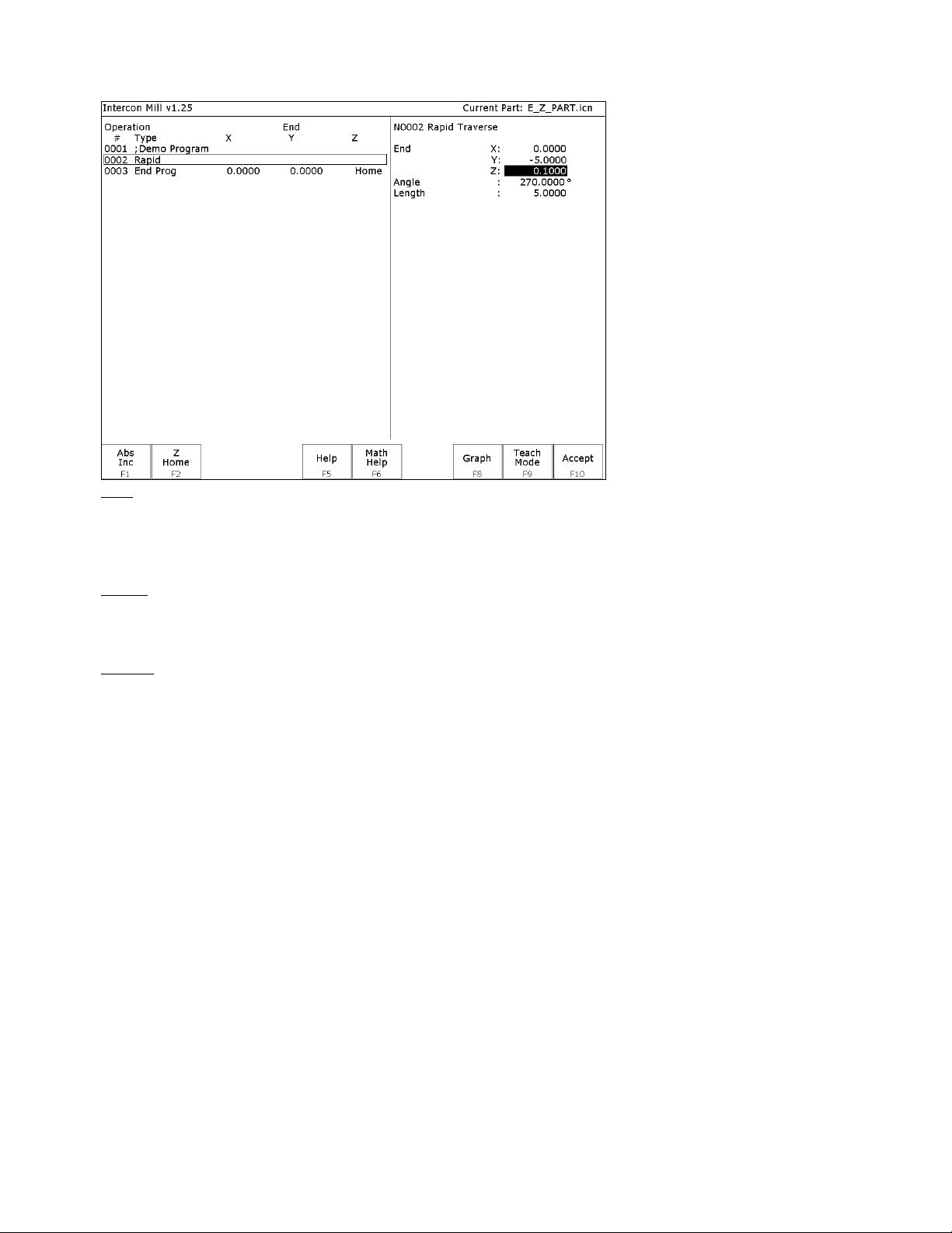
F1 - Rapid Traverse
the following screen:
Press F1 - Rapid from the Insert Operation screen to insert a Rapid Traverse. You may see
End: When you first access the rapid traverse screen, the cursor will be highlighting the first field, End X. This is the
X coordinate of where the cutter will be after the rapid traverse has been completed. Similarly, Y and Z represent the
coordinates of the cutter after the rapid traverse is completed. The angle and length fields will be computed if you
choose to enter the end point of the move.
Angle: The destination may also be specified in terms of a counterclockwise angle from the three o'clock position.
When combined with a length for the current move, the corresponding X and Y coordinates for the destination will be
calculated and placed in the correct fields. The Z destination will remain unchanged, however.
Length: The length of the rapid traversal. When combined with the angle of the current move, the corresponding X
and Y coordinates for the destination will be calculated and placed in the correct fields. The Z destination will remain
unchanged, however.
The F1 – Abs/Inc key toggles between incremental and absolute positioning modes in any of the fields where a
positional dimension is needed. For example: X, Y, or Z-axis dimensions can all be in incremental or absolute
coordinates, or a mixture of both. The length and angle fields cannot be incremental. These fields are absolute values.
The F2 - Z Home key may be used on the Z destination field to tie the ending Z coordinate to the Z home position.
This means that no matter what you’re Z home value is at the time that you run your program, the final Z position will
be the Z home position.
When you are finished entering all of the dimensions for the rapid move, press F10 - Accept to accept the operation
and return to the Insert Operation screen.
NOTE: When making rapid moves, if a Z destination higher than the current cutter position is specified, the
cutter will first be raised to the destination Z position, and then move linearly in X and Y to arrive at the
destination. If a Z destination lower than the current cutter position is specified, the cutter will move linearly in
X and Y first and then plunge Z to the destination Z position.
NOTE: The Rapid traverse operation can have rotary fields, if you have a rotary fourth axis. The rotary field
descriptions are the same as that of the Linear Mill operation.
M-Series Operator’s Manual 12/20/2013 10-7
Page 91
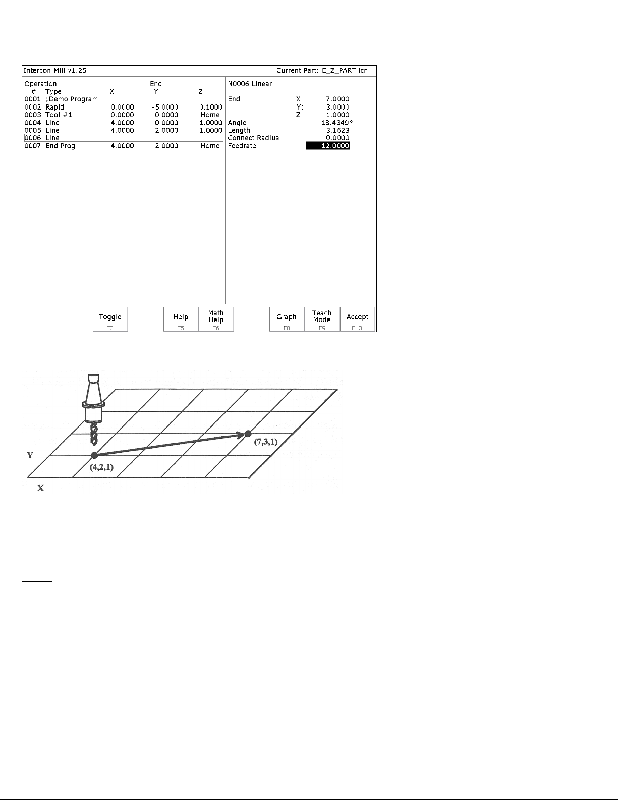
F2 - Linear Mill
If you press F2 - Linear from the Insert Operation screen, the following screen appears:
The numbers in the different fields on the screen correspond to the following Linear Mill example shown here
graphically:
End: When you first access the linear mill screen, the cursor will be highlighting the first field, End X. This is the X
coordinate of where the cutter will be after the linear move has been completed. Similarly, Y and Z represent the
coordinates of the cutter after the linear move is completed. The angle and length fields will be computed if you
choose to enter the end point of the move.
Angle: The destination may also be specified in terms of a counterclockwise angle from the three o'clock position.
When combined with a length for the current move, the corresponding X and Y coordinates for the destination will be
calculated and placed in the correct fields. The Z destination will remain unchanged, however.
Length: The length of the linear mill. When combined with the angle of the current move, the corresponding X and Y
coordinates for the destination will be calculated and placed in the correct fields. The Z destination will remain
unchanged, however.
Connect Radius: If you are performing two linear mill operations and you wish to have a rounded 'corner' between
them instead of a sharp peak, you may enter the radius of the 'corner' and Intercon will insert an arc between the linear
mill operations. This connect radius also works for blending a line into an arc operation.
Feedrate: Speed at which the cutter moves.
M-Series Operator’s Manual 12/20/2013 10-8
Page 92

The feedrate can be toggled to modal, fixed, or slave. This is indicated by the symbol beside the feedrate field. If the
feedrate is modal then it will have the “M” symbol or if it is fixed it will have the “F” symbol shown below. The slave
feedrate has no symbol and is set to the last modal feedrate set in the program, when the modal feedrate changes all the
following slave feedrates change until the next modal feedrate is encountered.
If you have a fourth axis installed and it is rotary, additional fields are shown for Linear Mill operations after the
feedrate field.
Degrees: The number of degrees you want to move the rotary axis. This value can be positive or negative and the
movement of the rotary axis will depend on the orientation of the axis.
Minutes: The number of minutes you want to move the rotary axis. Values for this field are between 0 and 59.
Seconds: The number of seconds you want to move the rotary axis. Values for this field are between 0 and 59.
Decimal degrees: This is another method of entering the number of degrees. If you choose to enter the movement of
the rotary axis with the fields listed above, the value of this field will be calculated automatically. If you choose to
enter the number of degrees with this field or make changes to it, then the degrees, minutes and seconds will be
calculated or changed automatically. Values for this field can be positive or negative.
Rotary movement defaults to zero degrees, incremental. To enter an absolute (rather than incremental) rotary position,
you must press F1 - Abs/Inc to toggle to absolute.
M-Series Operator’s Manual 12/20/2013 10-9
Page 93
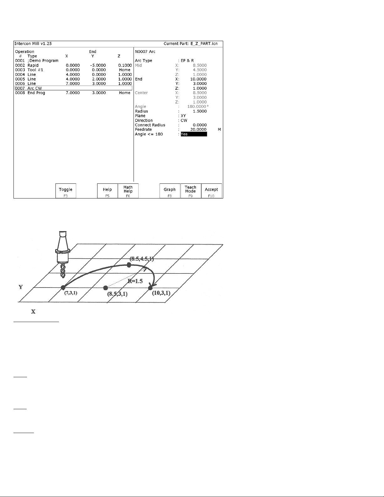
F3 - Arc Mill
If you press F3 - Arc for Arc Mill from the Insert Operation screen, the following screen appears:
The numbers in the different fields on the screen correspond to the following Arc Mill example shown here
graphically:
Operation Type: There are four ways to specify your ARC: using an endpoint and a radius (EP&R), using a center
point and an angle (CP&A), using a center point and an end point (CP&EP), or using a mid-point and an end point (3Point). The Three Point arc is designed to be used in conjunction with Teach Mode. When specifying a particular
kind of arc, you will not be able to modify certain fields. For example, if you are specifying an endpoint and a radius,
you will not be able to modify the mid point, center point and angle fields. This is because Intercon calculates the
correct values for these fields.
Mid: The X, Y, and Z coordinates of a point on the arc path somewhere between the start point and end point of the
arc. You will be able to modify this field only when specifying a Three Point arc. Also, the coordinate that does not lie
in the plane of the arc cannot be edited; it is automatically calculated.
End: The X, Y and Z coordinates of where the cutter will be once the arc move is complete. You will not be able to
edit this field if you are specifying a center point and angle (CP&A) arc.
Center: This is the X, Y and Z position of the center of the arc. You will not be able to edit this field if you are
specifying an end point and radius (EP&R) arc or a Three Point arc. Also, the coordinate that does not lie in the plane
of the arc cannot be edited; it is automatically carried forward from the last operation.
M-Series Operator’s Manual 12/20/2013 10-10
Page 94

Angle: Number of degrees through which the cutter will travel. This value must lie between 0 and 360 degrees. You
will be able to edit this field only if you are specifying a center point and angle (CP&A) arc.
Radius: Distance from the center of the arc to its edge. This value must be greater than 0. You will only be able to
edit this value if you are specifying an end point and radius (EP&R) arc.
Plane: This determines whether the arc is to be milled in the XY-, ZX- or YZ-plane. If any of the Z coordinate values
are tied to the Z home position, only XY-plane arcs may be selected.
Direction: Determines whether the arc moves clockwise (CW) or counterclockwise (CCW). Note that the direction of
XZ arcs is judged looking Y+ (i.e. from the front of the machine). This is natural, but it is opposite of the way arcs are
specified in G codes. Intercon automatically makes this translation when it generates CNC codes.
Connect Radius: This field works like the Linear Mill connect radius. It allows for the blending of an arc into the next
line or arc operation.
Feedrate: Speed at which the cutter moves.
The feedrate can be toggled to modal, fixed or slave, this is indicated by the symbol beside the feedrate field. If the
feedrate is modal then it will have the “M” symbol or if it is fixed it will have the “F” symbol shown below. The slave
feedrate has no symbol and is set to the last modal feedrate set in the program, when the modal feedrate changes all the
following slave feedrates change until the next modal feedrate is encountered.
Angle <= 180º: For end point and radius (EP&R) arcs, this field determines whether the arc is to be less than (YES) or
greater than (NO) 180 degrees.
M-Series Operator’s Manual 12/20/2013 10-11
Page 95

F4 - Tool Functions
When you select the tool functions by pressing F4 - Tool the following screen appears:
The following parameters for this tool change are as follows:
Tool Number: Number of the tool (between 1 and 200) to use. Entering this value pulls the current settings for this
tool from the CNC software tool library. You may then edit the length offset, diameter offset and diameter values if
you wish to redefine your tool. The length value is not editable.
Description: Description of the tool selected above, from the tool library.
Position: X and Y coordinates for the place at which the tool change will occur. This should be a place at which the
current tool can be removed from the quill and the new tool can be inserted.
Tool H Offset: Index in the offset library (between 0 and 200) of the actual tool height offset.
Tool Height: Tool height associated with the H offset selected above. This field is not editable.
Tool D Offset: Index in the offset library (between 0 and 200) of the actual tool diameter.
Tool Diameter: Tool diameter associated with the D offset selected above.
Spindle Speed: Speed at which the spindle will rotate when the spindle is started after the tool change.
Spindle Direction: Direction in which the spindle will turn after the tool change. If this is set to CW or CCW, the
spindle will be started automatically after the tool change. Press F3 - Toggle or SPACE to toggle between CW, CCW,
and Off.
Coolant Type: Type of coolant to activate after the tool change. If this is set to Flood or Mist, the selected coolant
system will be started automatically after the tool change. Press F3 - Toggle or SPACE to toggle between Flood,
Mist, and Off.
M-Series Operator’s Manual 12/20/2013 10-12
Page 96
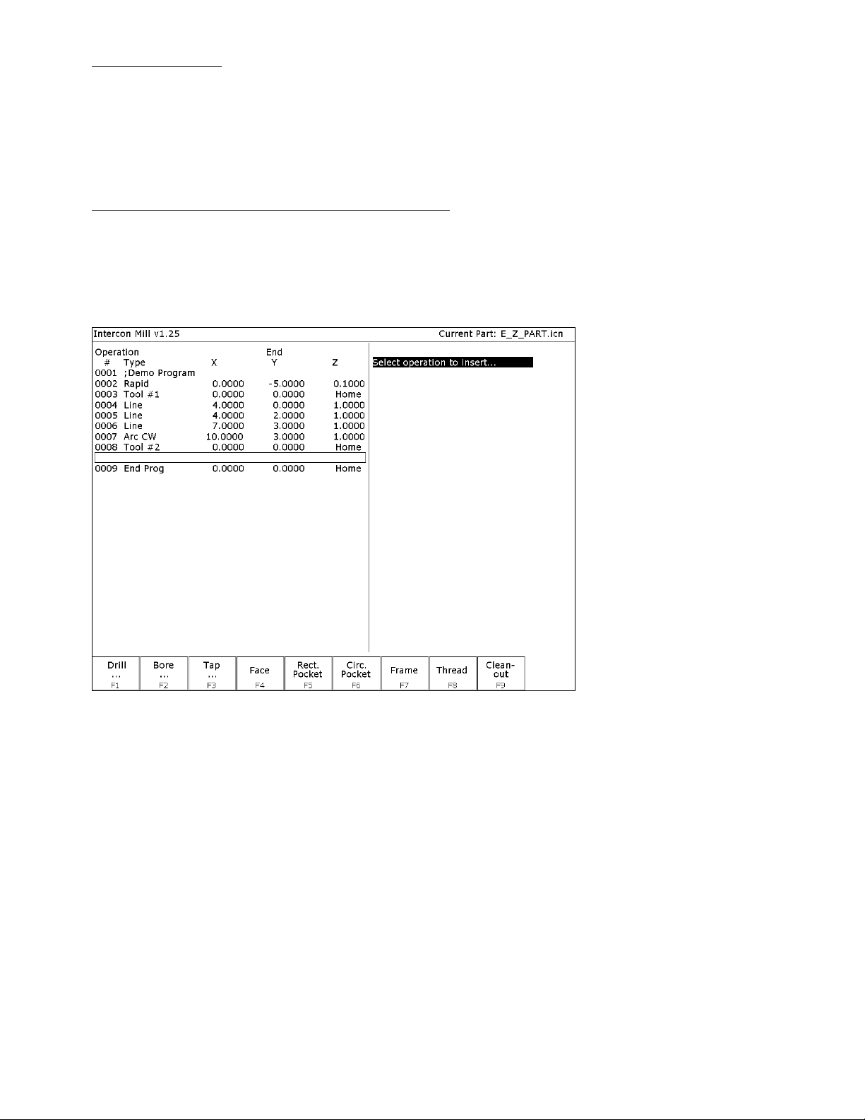
Actual Tool Change: Determines whether an M6 code is generated (answer Yes) during the tool change. If you do not
want to remove the current tool, but instead want to alter its diameter or length offsets (e.g. for doing a finish pass
while using cutter compensation, you may want to use a diameter offset which is slightly larger than the actual tool for
the first passes, then use the actual tool diameter for the finish pass), answer No to this question. Spindle and coolant
will not be automatically turned off if you answer No here.
Press F10 - Accept, Page Up, or Page Down when you are finished to accept these values and make changes to the
tool library. If you have changed any field other than the Tool Number of the Actual Tool Change field or position,
you will make changes to the CNC software Tool Library. At the end of the program, Intercon always turns off the
spindle and coolant and returns the Z-axis to the home position. These codes do not need to be entered at the end of
your program.
F5 - Canned Cycles
appears:
When you choose the Canned Cycle operation by pressing F5 - Cycles, the following screen
M-Series Operator’s Manual 12/20/2013 10-13
Page 97
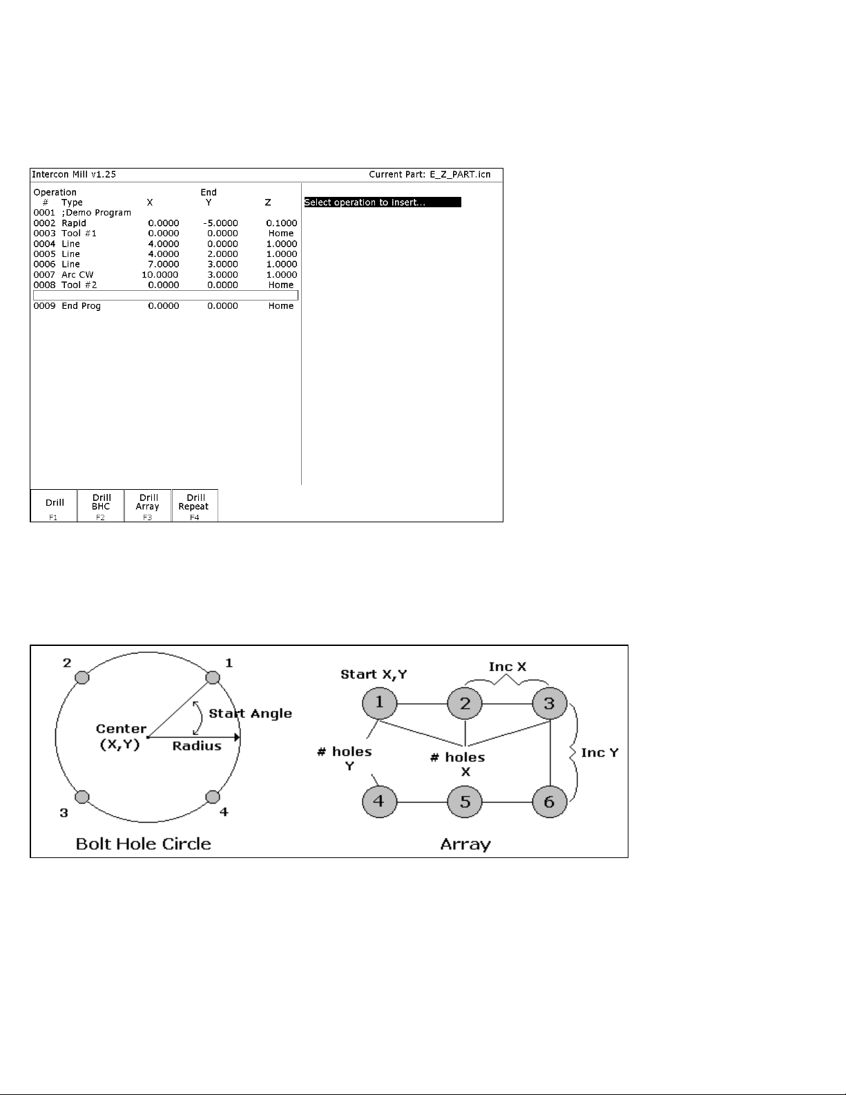
Canned Cycle Introduction #1: Using Pattern and Repeat
(Drilling, boring, tapping)
Selecting F1 - Drill will give you four choices; F1 – Drill, F2 – Drill BHC, F3 – Drill Array, or F4 – Drill Repeat.
F2 - Bore and F3 - Tap will have the same menu selections as drill except they will display Bore or Tap cycles
All canned cycle operations using the Drill BHC (Bolt Hole Circle) or Drill Array are identical to their equivalent
using the F1 - Drill single hole selection. The use of the Drill BHC or Drill Array, however, offers the option to drill
more than one hole in a pattern dictated by the new fields in the menu. F4 - Drill Repeat allows the user to repeat a
set of holes with a different type drilling, boring or tapping operation with out re-entering the X, Y coordinates.
The Bolt Hole Circle and array patterns are explained graphically in the following figure:
M-Series Operator’s Manual 12/20/2013 10-14
Page 98
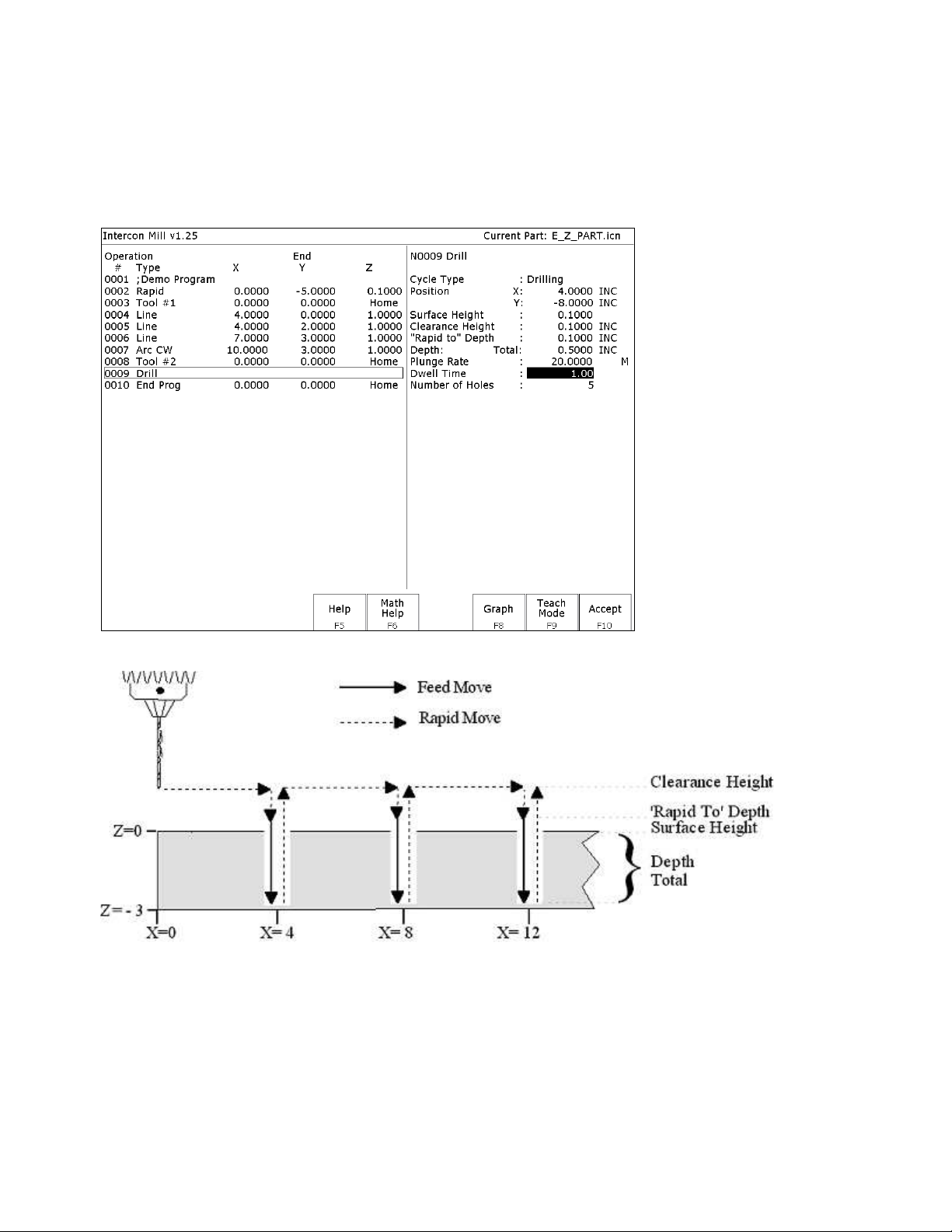
Canned Cycle Introduction #2: Linear Repetition of Operations
(Drilling, Boring, Tapping)
If you want to perform one operation several times in a linear pattern, simply define Position X, Y or both as
incremental values. To do this, use the F1 – Abs/Inc Key. This key will toggle the Position value mode between
incremental and absolute. If you define X and/or Y as incremental values, a new field will appear asking for the
number of holes:
The numbers in the fields on the screen correspond to the following example, shown here graphically:
M-Series Operator’s Manual 12/20/2013 10-15
Page 99

Drilling (F1 in the Canned Cycle Menu: option #1)
If you press F1 - Drill from the Canned Cycle Menu, you will gain access to three types of drilling operations:
Drilling, Chip Breaking, and Deep Hole drilling. The current drilling operation in use is reflected in the field “Cycle
Type” and pressing F3 - Toggle or SPACE toggles between all three. In this section we will examine the first option:
Drilling.
The numbers in the fields on the screen correspond to the following example, shown here graphically:
Where:
Cycle Type: Selects one of three drilling operations: Drilling, Chip Breaking, or Deep Hole drilling. Press F3 -
Toggle or SPACE to toggle between the three choices.
Position: Specifies the X and Y coordinates where the drilling will take place. If either the X or Y coordinate is an
incremental value, you will have the option to drill multiple holes in a linear pattern (See Canned Cycle Introduction
#2).
Surface Height: Absolute Z-axis position from where each incremental depth is measured.
M-Series Operator’s Manual 12/20/2013 10-16
Page 100
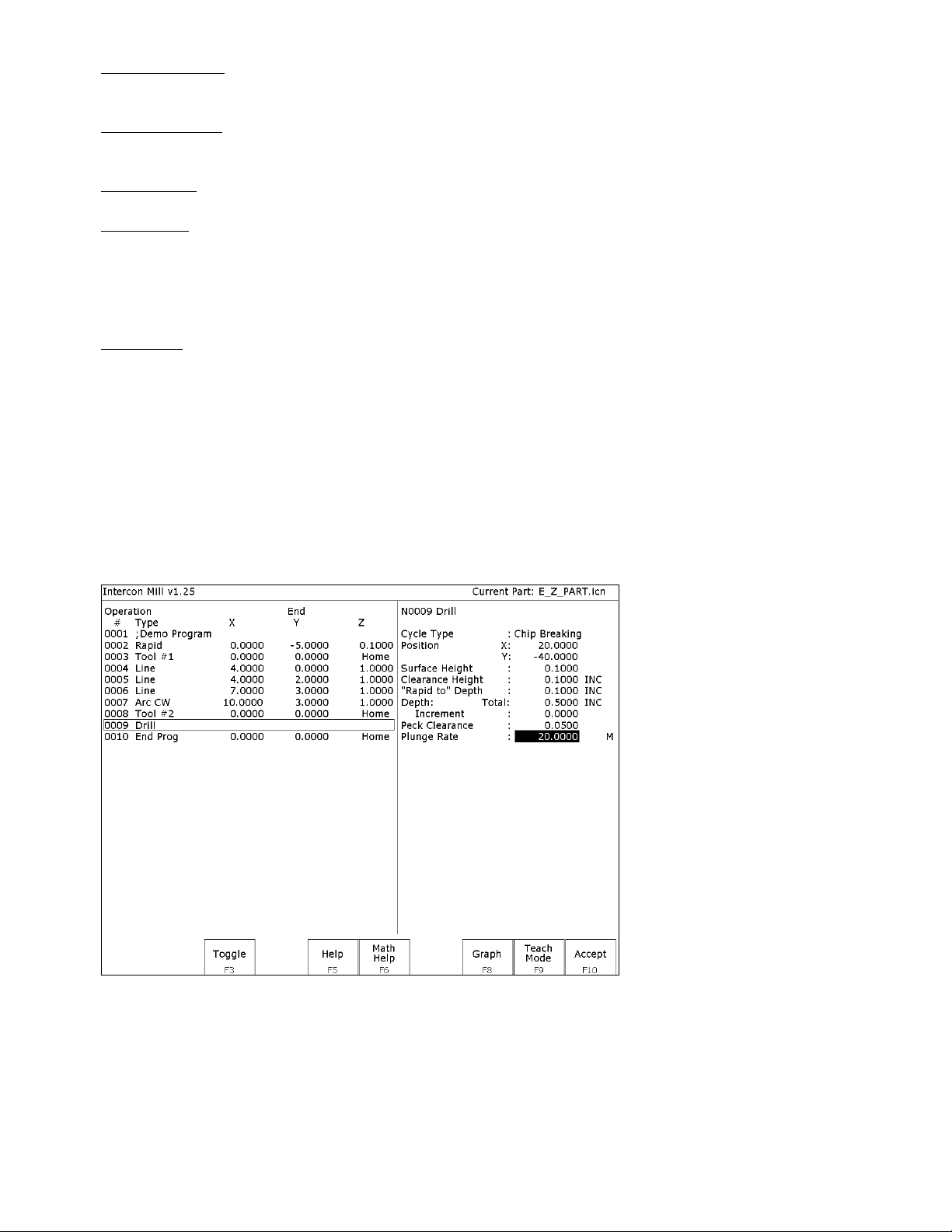
Clearance Height: This parameter specifies the Z-axis height used when performing rapid moves to the position of
each hole being drilled.
'Rapid To' Depth: The depth to which the cutter rapid moves before beginning to drill the hole at the specified Plunge
Rate. This is below the Clearance Height but above the Surface Height.
Depth: Total: Depth of hole (incremental) as measured from Surface Height.
Plunge Rate: Z-axis speed of descent during drilling.
The plunge rate can be toggled to modal, fixed or slave, this is indicated by the symbol beside the plunge rate field. If
the plunge rate is modal then it will have the “M” symbol or if it is fixed it will have the “F” symbol. The slave plunge
rate has no symbol and is set to the last modal plunge rate set in the program, when the modal plunge rate changes all
the following slave plunge rates change until the next modal plunge rate is encountered.
Dwell Time: Delay at bottom of hole before starting ascent.
Drilling provides a rapid to the hole position at the Clearance Height, followed by a rapid Z down to the 'Rapid To'
Depth. Next is a feedrate down to the specified depth. If a Spot facing cycle is desired, enter a value in the dwell time
field and the cutter will wait the desired amount of time before performing a rapid move up to the Clearance Height.
Chip Breaking (F1 in the Canned Cycle Menu: option #2)
If you press F1 - Drill from the Canned Cycle Menu you will gain access to three types of drilling operations:
Drilling, Chip Breaking, and Deep Hole drilling. The current drilling operation in use is reflected in the field Cycle
Type, and pressing F3 - Toggle or SPACE toggles between all three. In this section we will examine the second
option: Chip Breaking.
The numbers in the fields on the screen correspond to the following example, shown here graphically:
M-Series Operator’s Manual 12/20/2013 10-17
 Loading...