

Page 1
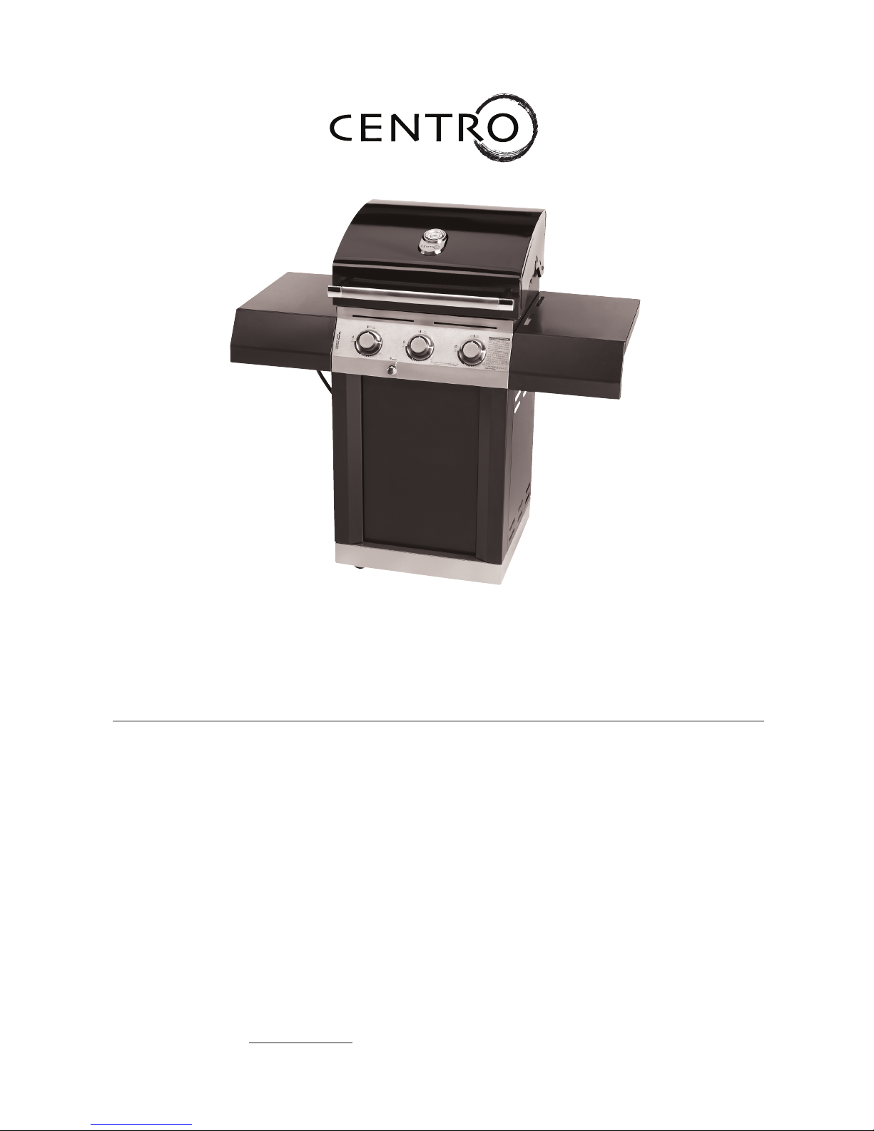
Centro 2800
Assembly Manual
85-1614-2 (G41201) Propane
85-1650-4 (G41202) Natural Gas
Limited 3-Year Warranty
Read and save manual for future reference.
Assemble your grill immediately.
Missing or damaged parts should be
claimed within 15 days of purchase.
Manual Revision #: 121407
Page 2
DANGER
1. If you smell Gas:
a. Shut o gas to the appliance
b. Extinguish any open ame
c. Open lid
d. If odor continues, keep away from
the appliance and immediately
call your gas supplier or your
re department
2. Do not store or use gasoline or other
ammable vapours and liquids in the
vicinity of this or any other appliance.
3. An LP cylinder not connected for use shall
not be stored in the vicinity of this or any
other appliance.
4. Requires two people to complete the
assembly process.
5. Beware of sharp edges.
WARNING
Failure to follow all of the Manufacturer’s
instructions could result in hazardous res,
explosions, property damage, or serious
personal injury or even death.
Follow all leak check procedures carefully
prior to operation of barbecue, even if grill
was dealer assembled. Do not try to light
this barbecue without reading the Lighting
Instructions section of this manual.
THIS MANUAL MUST REMAIN WITH THE PRODUCT AT ALL TIMES
To ORDER non-warranty replacement parts or accessories, or to register your warranty,
please visit us on the web at
www.centrobbqs.com.
CAUTION
Re ad a nd follow all safet y st atement s,
as sembly in structions, and use and care
directions before attempting to assemble
and cook.
CAUTION
Sharp edges. Wear gloves when assembling
your grill.
THIS BARBECUE IS FOR OUTDOOR USE ONLY
CONTACT CALL CENTRE IF ANY PARTS ARE MISSING
INSTALLER OR ASSEMBLER/CONSUMER
This manual should be kept with the BBQ at
all times.
HEAVY ARTICLE NEEDS 2 TO LIFT
Page 3
1
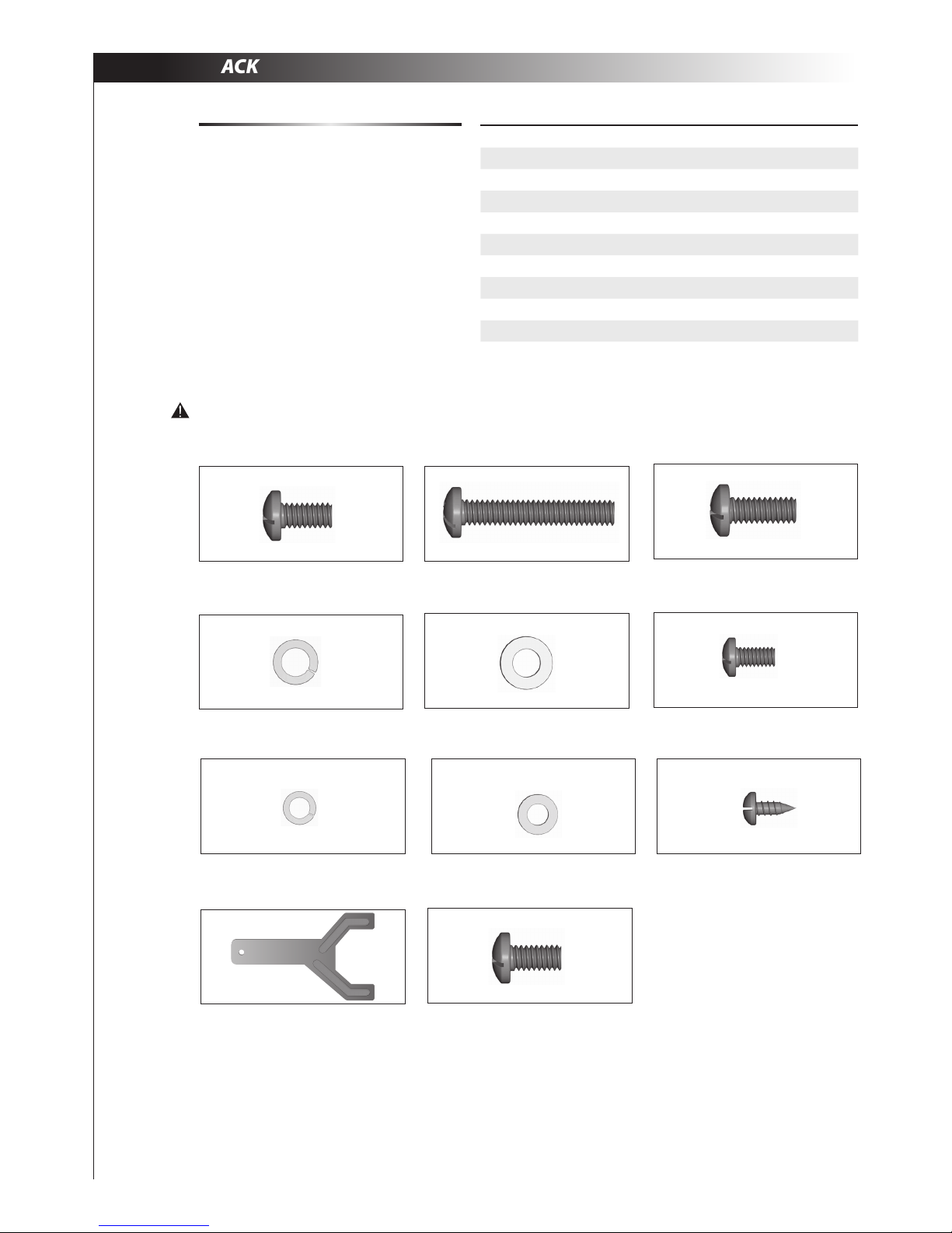
HARDWARE PACK
TOOLS NEEDED FOR ASSEMBLY
• #2 Phillips screwdriver (long and short)
• ¼” Slotted screwdriver (long and short)
• Adjustable wrench
• Pliers
Before assembling the barbecue, read these
instructions carefully.
Assemble the barbecue on a at, clean surface.
Grill is heavy. You should have at least two people
assemble the barbecue together.
Notes: Do not fully tighten all the nuts during this
initial stage.
No. Description Part Number Quantity
1 1/4"-20UNCX13 Screw 20120-13013-250 6
2 1/4"-20UNCX38 Screw 20120-13038-250 4
3 1/4"-20UNCX16 Screw 20120-13016-250 4
4 ø7 Lock Washer 41400-07000-250 14
5 ø7 Washer 40300-07000-250 14
6 NO.10-24UNCx10 Screw 20124-10010-250 20
7 ø 5 Lock Washer 41400-05000-250 24
8 ø 5 Washer 40300-05000-250 24
9 ST4.2x10 Tapping Screw 22500-42010-137 1
10 Wrench G413-0032-9082 1
11 NO.10-24UNCx13 Screw 20124-10013-250 4
1. ¼” - 20UNCX13 Screw (x6)
4. ø7 Lock Washer (x14)
9. ST4.2x10 Tapping Screw (x1)
2. ¼” - 20UNCX38 Screw (x4)
5. ø7 Washer (x14)
7. ø5 Lock Washer (x24)
3. ¼” - 20UNCX16 Screw (x4)
6. NO. 10-24UNC10 Screw (x20)
8. ø5 Washer (x24)
Caution:
Sheet metal can cause injury. Wear gloves when installing the grill.
#10. Wrench (x1)
#11. NO. 10-24UNCx13 Screw (x4)
Page 4

2
Item No. Quantity Description Part No.
AA 1 Top Lid G412-0100-01
AB 1 Lid handle G412-0004-01
AC 1 Lid handle end cap-Left G617-0004-01
AD 1 Lid handle end cap-Right G617-0005-01
AE 1 Logo Plate G412-0001-01
AF 1 Thermometer G412-0003-01
AG 2 Screw for Top Lid G501-0005-01
AH 2 Lid Bumper G508-0063-01
BA1 1 Burner Box Weldment G412-0200-01
BA2 1 Rear Panel, Burner Box G416-0013-01
BB 1 Upper side panel- Left G412-0400-01
BC 1 Upper side panel- Right G412-0300-01
BD 3 Main Burner G413-5000-01
BE 2 Carryover assembly G413-0004-01
BF 3 Flame Tamer G413-0036-01
BG 2 Cooking Grate G412-0015-01
BH 1 Warming Rack G413-0002-01
BI 1 Upper Back Panel G412-0002-01
BJ 1 Match Holder G608-0019-01
CA 1 Manifold Assembly G412-4000-01
CB 1 Regulator- 22" G606-0008-01
CC 3 Control Knobs G412-4500-01
CD1 1 Electronic Igniter assembly G501-0072-02
CD2 1 Electronic Ignition Button G501-0072-01
CE1 1 Electrode Set, Main Burner G412-0009-01
CE2 1 Ground wire, main burners G411-0004-01
CF 1 Control Panel G412-0005-01
CG 1 Heat shield
CH 1 Series Logo G412-0016-01
CI 1 Grease Tray G412-1000-01
CJ 1 Grease Cup G416-0015-01
DA 1 Side shelf table- Left G501-0900-01
DB 1 Side Shelf fascia- Left G412-0011-01
DC 1 Side shelf table- Right G501-0800-01
DD 1 Side shelf fascia-Right G412-0010-01
DE 1 Cart side panel-Left G412-0500-01
DF 1 Cart Side Panel, Right G412-0600-01
DG 2 Pillars G412-0013-01
DH 1 Front Panel G412-0012-01
DI 1 Bottom Shelf G412-0700-01
DJ 2 Wheel with lock G401-0061-01
DK 2 Wheel G607-0048-01
1 Hardware Pack G412-B001-01
1 Assembly Manual G412-M001-01
1 Safety & Care Manual G617-M001-02
PARTS LIST (PROPANE) FOR 85-1614-2 (G41201)
Page 5
3
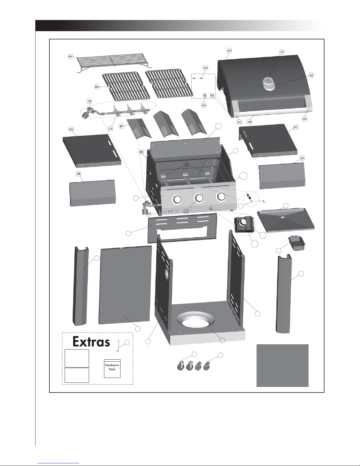
EXPLOADED DIAGRAM (PROPANE) FOR 85-1614-2 (G41201)
DK
DJ
DI
DF
DE
DH
BJ
Safety & Care
Manual
Assembly
Manual
DG
CD2
CD1
BI
DG
CJ
CI
CE
BE
BA2
BC
BA1
CF
Heat shield
Page 6

4
PARTS LIST (NATURAL GAS) FOR 85-1650-4 (G41202)
Item No. Quantity Description Part No.
AA 1 Top lid G412-0100-01
AB 1 Lid handle G412-0004-01
AC 1 Lid handle end cap-Left G617-0004-01
AD 1 Lid handle end cap-Right G617-0005-01
AE 1 Logo plate G412-0001-01
AF 1 Thermometer G412-0003-01
AG 2 Screw for top lid G501-0005-01
AH 2 Lid bumper G508-0063-01
BA1 1 Burner box weldment G412-0200-01
BA2 1 Rear panel, burner box G416-0013-01
BB 1 Upper side panel- Left G412-0400-01
BC 1 Upper side panel- Right G412-0300-01
BD 3 Main burner G413-5000-01
BE 2 Carryover assembly G413-0004-01
BF 3 Flame tamer G413-0036-01
BG 2 Cooking grate, G412-0015-01
BH 1 Warming rack G413-0002-01
BI 1 Upper back panel G412-0002-01
BJ 1 Match holder G608-0019-01
CA 1 Manifold assembly G412-4100-01
CB 1 Natural gas hose G501-0099-01
CC 3 Control knobs G412-4500-01
CD1 1 Electronic igniter assembly G501-0072-02
CD2 1 Electronic ignition button G501-0072-01
CE1 1 Electrode set, main burner G412-0009-01
CE2 1 Ground wire, main burners G412-0004-01
CF 1 Control panel G412-0005-01
CH 1 Series logo G412-0016-01
CI 1 Grease tray G412-1000-01
CJ 1 Grease cup G416-0015-01
DA 1 Side shelf table- Left G501-0900-01
DB 1 Side shelf fascia- Left G412-0011-01
DC 1 Side shelf table- Right G501-0800-01
DD 1 Side shelf fascia-Right G412-0010-01
DE 1 Cart side panel-Left G412-0500-01
DF 1 Cart side panel, Right G412-0600-01
DG 2 Pillars G412-0013-01
DH 1 Front panel G412-0012-01
DI 1 Bottom shelf G412-0800-01
DJ 2 Wheel with lock G401-0061-01
DK 2 Wheel G607-0048-01
1 Hardware Pack G412-B001-01
1 Assembly Manual G412-M001-01
1 Safety & Care Manual G617-M001-02
Page 7
5
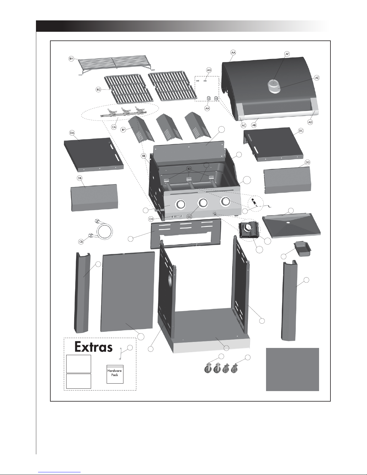
EXPLOADED DIAGRAM (NATURAL GAS) FOR 85-1650-4 (G41202)
BE
BA2
BC
BA1
BI
DG
DE
DH
BJ
Safety & Care
Manual
Assembly
Manual
DK
DJ
DI
DF
CD2
CD1
CI
CJ
DG
CE
CF
Heat shield
Page 8
6
1
2
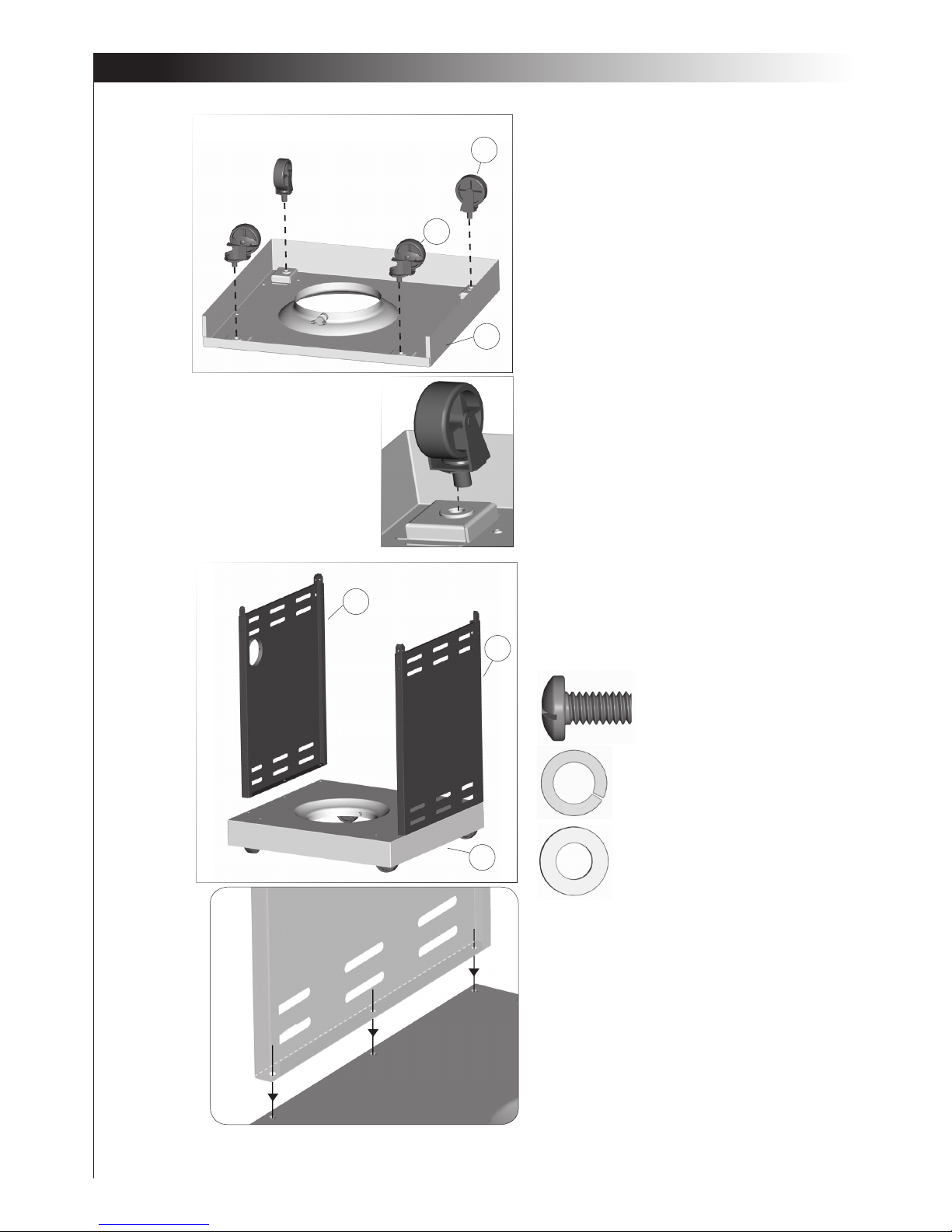
#1 - ¼” - 20UNCx13 Screw (x6)
#4 - ø7 Lock Washer (x6)
#5 - ø7 Washer (x6)
ASSEMBLY INSTRUCTIONS
DK
DE
DF
DI
DJ
DI
Front view
1. Separate the 2 dierent types of wheels, 2
locking wheels (DJ) and 2 regular wheels (DK).
Attach the locking wheels (DJ) to the back of
the bottom shelf (DI) and the regular wheels
(DK) to the front of the bottom shelf (DI).
To secure the 4 wheels, hand tighten rst.
Then, tighten further using the Wrench provided in the hardware pack.
2. Ensure that the wheels are rmly locked in the
“ON” position before continuing.
Assemble the left side panel (DE) and the right
side panel (DF) to the bottom shelf (DI).
Page 9
7
3
4
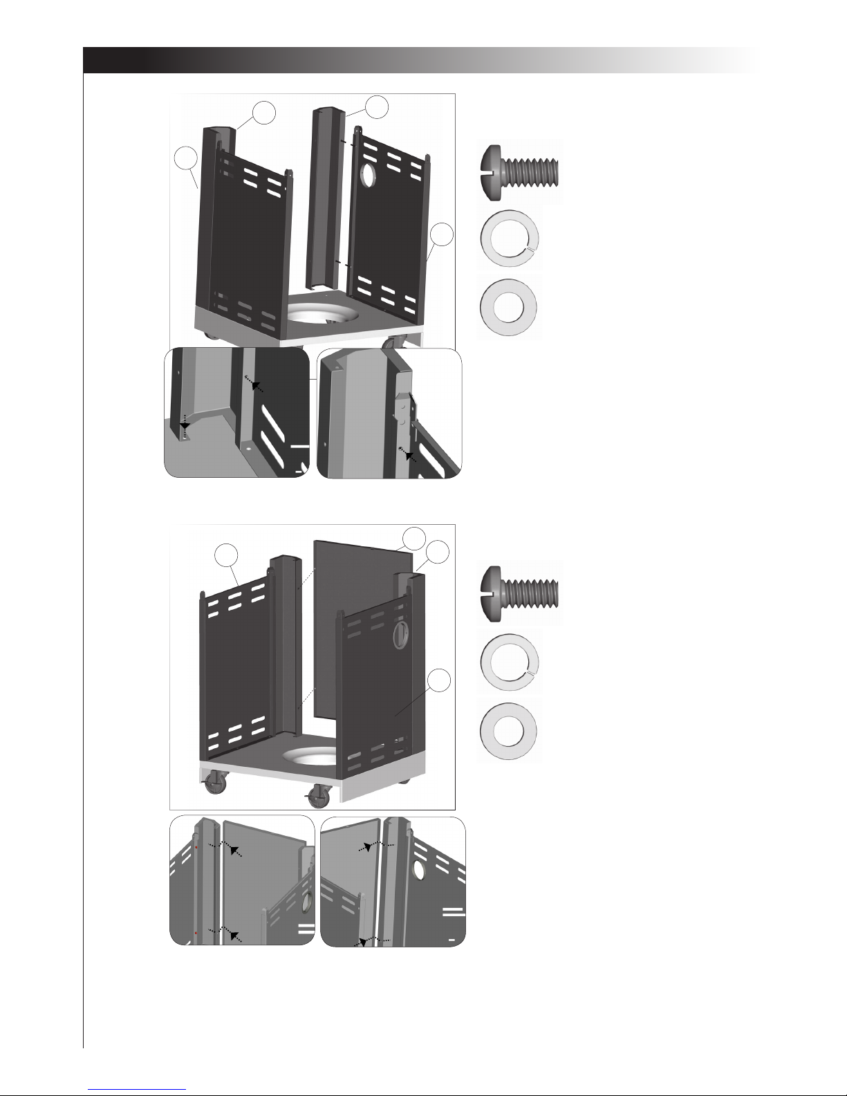
4. Attach the front panel (DH) onto the pillars (DG).
#6 - NO. 10-24UNCx10 Screw (x4)
#6 - NO. 10-24UNCx10 Screw (x6)
#7 - ø5 Lock Washer (x4)
#7 - ø5 Lock Washer (x6)
#8 - ø5 Washer (x4)
#8 - ø5 Washer (x6)
ASSEMBLY INSTRUCTIONS
DF
DF
DG
DG
DG
DH
DE
Back view
3. Assemble the Left and right Pillars (DG), to the
cart side panels, as shown in gure A and B.
A
B
DE
Page 10
8
5
6
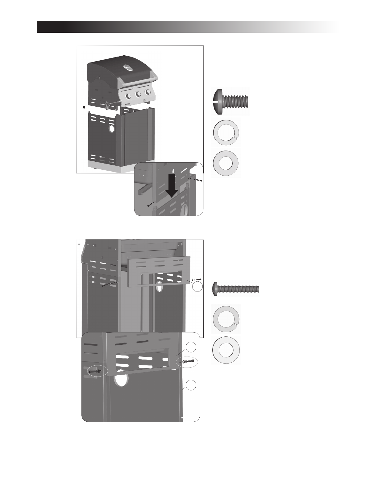
5. Position the top lid and burner box assembly
(A and B) onto the cart assembly (C) as shown.
in gure A. Use the hardware to connect both
parts, on the left and right sides, at the two
points indicated in Figure B.
#2 - ¼” - 20UNCx38 Screw (x2)
#6 - NO.10-24UNCx10 Screw (x4)
#4 - ø7 Lock Washer (x2)
#7 - ø5 Lock Washer (x4)
#5 - ø7 Washer (x2)
#8 - ø5 Washer (x4)
ASSEMBLY INSTRUCTIONS
BI
Rear view
BI
DE
6. Attach the upper back panel (BI) to both the
left and right side panels (DE and DF).
Only install hardware in the bottom portion of
the back panel, as shown in gure B.
A
B
Page 11
9
7
8
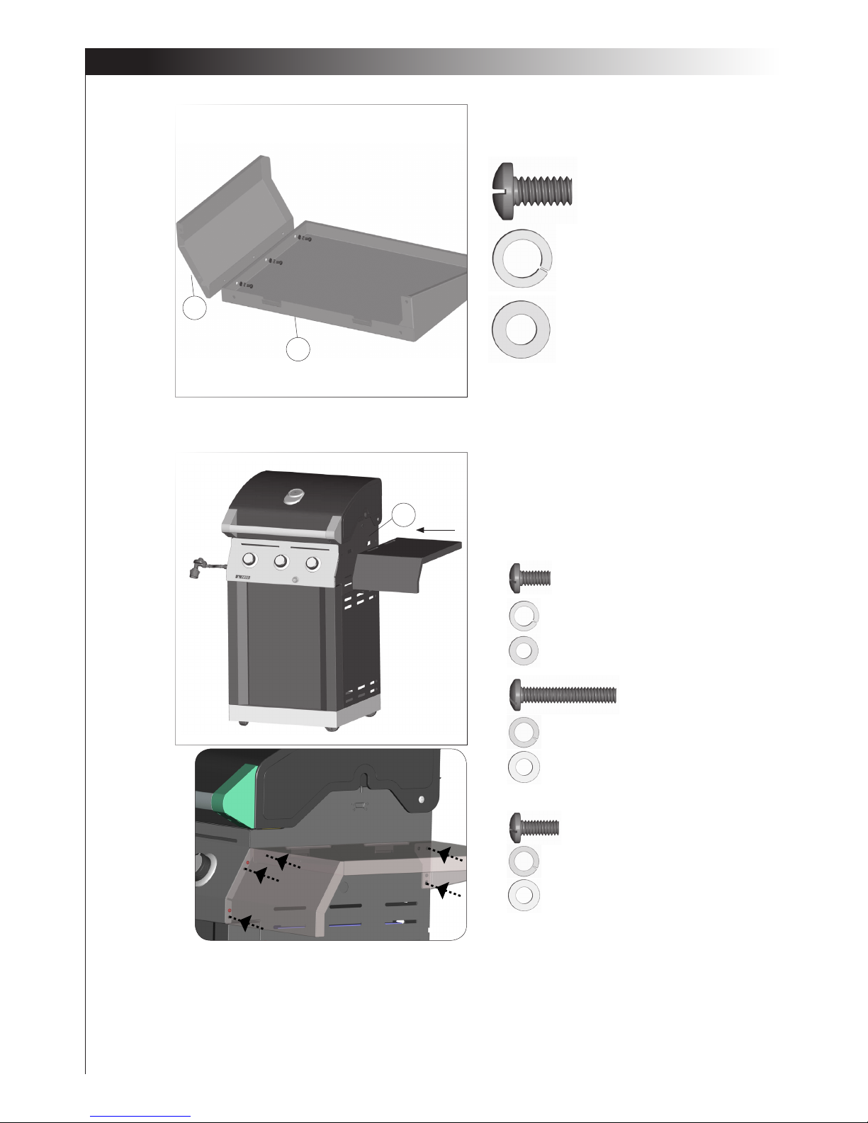
7. Attach the right side shelf fascia(DD) to the right
side shelf (DC).
TIP: To position the side shelf, insert the two hooks
on the side right shelf assembly into the two openings located on the upper right side panel (BC).
8. Assemble the right side shelf assembly to the cart
assembly, as shown in gure B.
#11 - NO.10-24UNCx13 Screw (x2)
#7 - ø5 Lock Washer (x2)
#6 - NO. 10-24UNCx10 Screw (x3)
#8 - ø5 Washer (x2)
#7 - ø5 Lock Washer (x3)
#8 - ø5 Washer (x3)
ASSEMBLY INSTRUCTIONS
#4 - ø7 Lock Washer (x2)
#2 - ¼” - 20UNCx38 Screw (x1)
#5 - ø7 Washer (x2)
#3 - ¼” - 20UNCx16 Screw (x2)
DD
DC
Front
Back
*
A
B
BC
*
K
K
K
L
L
L
#4 - ø7 Lock Washer (x1)
#5 - ø7 Washer (x1)
Page 12
10
9
10
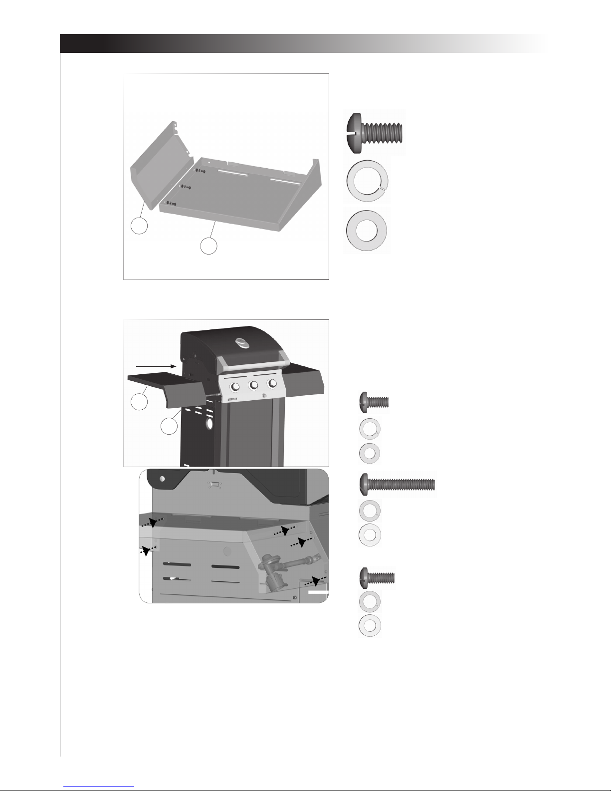
9. Attach the left shelf fascia (DB) to the left side
shelf (DA).
TIP: To position the side shelf, insert the two hooks
on the side shelf assembly into the two openings
located on the upper side panel (BE).
10. Assemble the right side shelf assembly to the cart
assembly, as shown in gure B.
ASSEMBLY INSTRUCTIONS
DA
DB
DA
DB
Front
Back
#6 - NO. 10-24UNCx10 Screw (x3)
#7 - ø5 Lock Washer (x3)
#8 - ø5 Washer (x3)
*
A
B
#11 - NO.10-24UNCx13 Screw (x2)
#7 - ø5 Lock Washer (x2)
#8 - ø5 Washer (x2)
#4 - ø7 Lock Washer (x2)
#2 - ¼” - 20UNCx38 Screw (x1)
#5 - ø7 Washer (x2)
#3 - ¼” - 20UNCx16 Screw (x2)
*
K
L
#4 - ø7 Lock Washer (x1)
#5 - ø7 Washer (x1)
K
K
L
L
*
Page 13
11
11
12
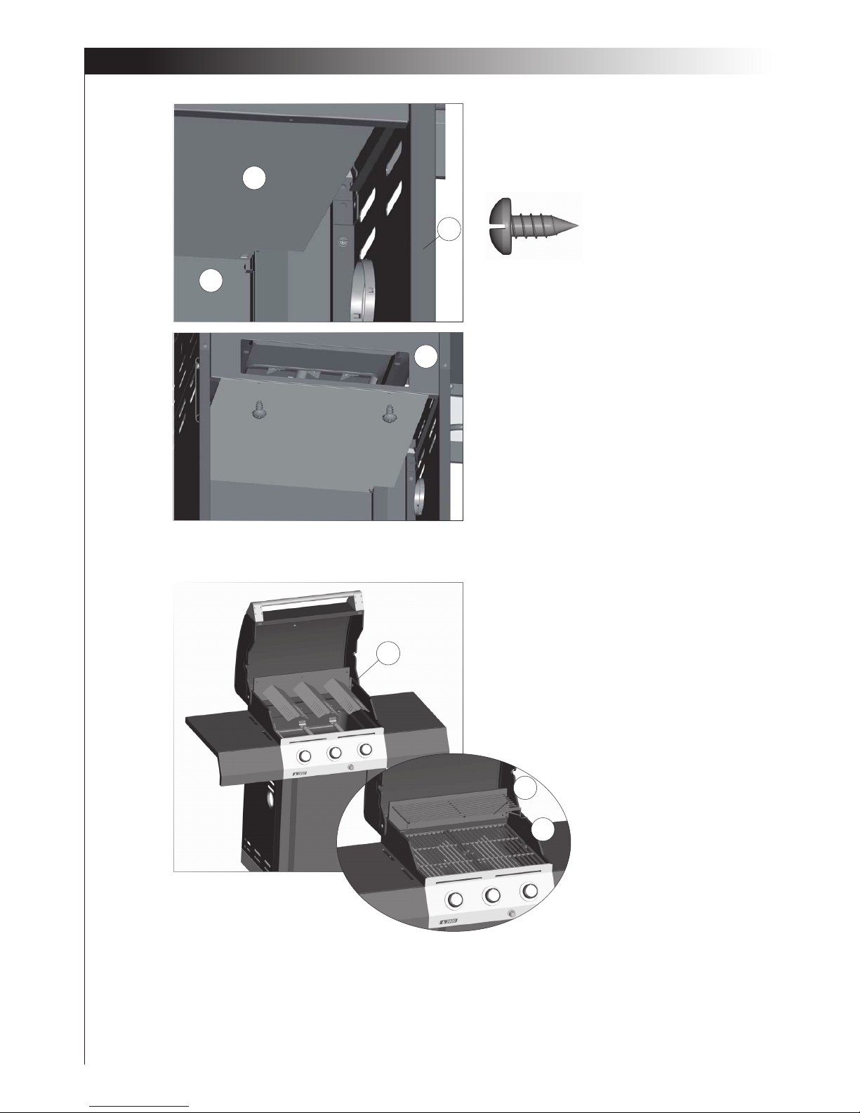
11. Place the heat shield (CG) into the groove which
is located at the back side of the front panel as
shown in gure A. Next, attach the heat shield
(CG) to the upper back panel (BI) by using the self
tapping screw (x2), as shown in gure B.
12. First place the ame tamers (BF) and then the
cooking grates (BG) into the burner box.
Place the warming rack (BH) onto the burner box.
ASSEMBLY INSTRUCTIONS
BF
CG
DH
DE
BI
#9 - ST4.2x10 Tapping Screw (x2)
BH
BG
Back view
A
B
Page 14
12
13
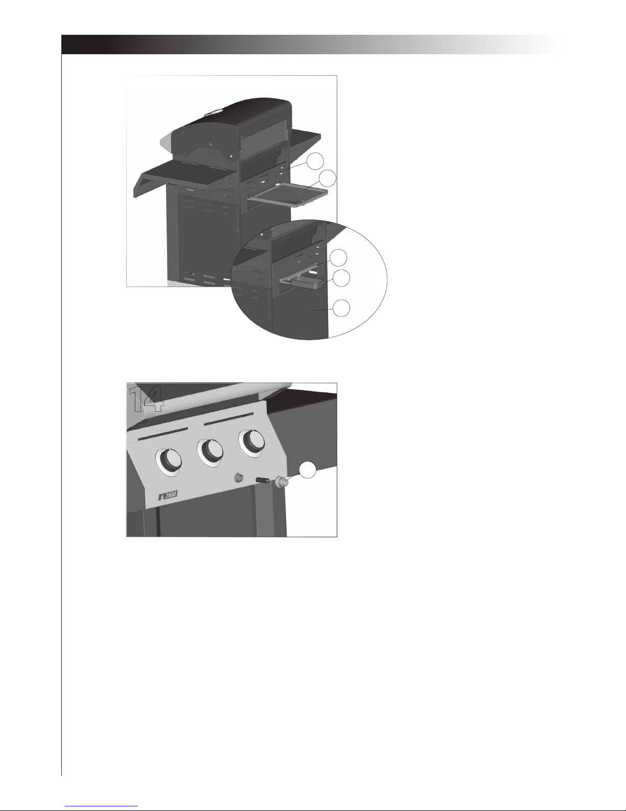
13a. Insert the grease tray (CI) into the opening
in the upper back panel (BI), making sure to
engage tracks located under burner box.
13b. Place the grease cup (CJ) onto the tracks,
located opn the underside of the grease
tray (CI).
ASSEMBLY INSTRUCTIONS
14
BI
CI
Back view
CI
CJ
DE
14. Unscrew the electronic ignitor button (CD2)
and insert one AA battery into the electronic
igniter battery compartment, with the positive
end facing outward.
* Battery not included.
CD2
Page 15
13
16
For natural gas model only.
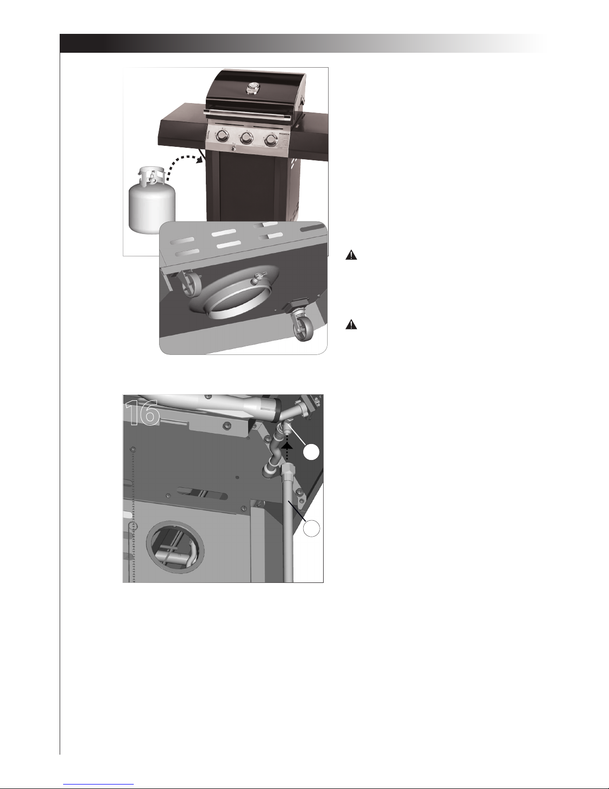
16. Attach the Natural Gas Hose(CB) to the side
burner valve(CC) as shown.
CB
CC
ASSEMBLY INSTRUCTIONS
For propane model only.
15a. Position the 20 lb propane tank onto the
bottom shelf (EG), and secure using the bolt
(already attached) located on the underside
of the bottom shelf, as shown in gure B.
15b. Attach the Regulator coupling nut to the LP
cylinder valve.
ATTENTION: For your families safety, do
not attempt to light this BBQ until you have
reviewed pages 4-7 of the CENTRO Safe Use
and Care Manual. All Safety and Leak test
MUST BE PERFORMED BY THE END USER,
prior to lighting this BBQ.
WARNING
Do not store extra propane tanks within
BBQ cart.
A
B
15
 Loading...