

Page 1
1
Version 1.4 January 2018
Operation and maintenance manual
Unit number 0000
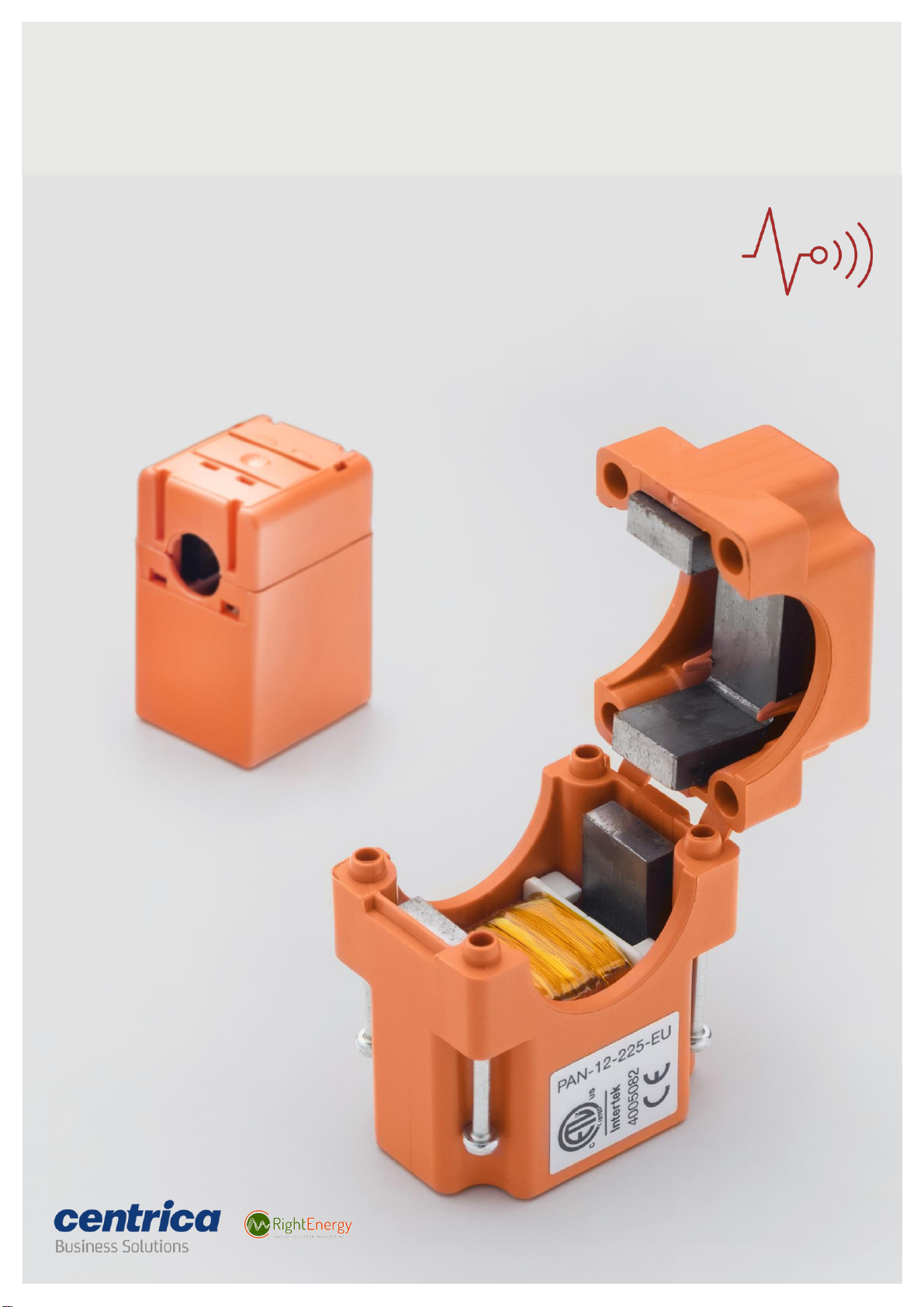
PAN-10 and PAN-12 Sensor installation guide
Page 2

Revision 1.4 January 2018
© 2018 Centrica plc. Registered office: Millstream, Maidenhead Road, Windsor, Berkshire. SL4 5GD.
Registered in England & Wales No 3033654
2
PAN-10 and PAN-12 Sensor installation guide
Copyright notice
Copyright© 2012-2017 Panoramic Power Ltd. All rights reserved.
Panoramic Power® is a registered trademark of Panoramic Power Ltd.
All other trademarks are the property of their respective owners.
FCC compliance statement
This device has been tested and found to comply with the limits for a Class B
digital device, pursuant to Part 15 of the FCC Rules. These limits are designed to
provide reasonable protection against harmful interference in residential
installations. This equipment generates uses and can radiate radio frequency
energy and, if not installed and used in accordance with the instructions, may
cause harmful interference to radio and television reception.
However, there is no guarantee that interference will not occur in a particular
installation. If this device does cause such interference, which can be verified by
turning the device off and on, the user is encouraged to eliminate the
interference by one or more of the following measures:
• Re-orient or re-locate the receiving antenna.
• Increase the distance between the device and the receiver.
• Connect the device to an outlet on a circuit different from the one that
supplies power to the receiver.
• Consult the dealer or an experienced radio/TV technician.
Warning Changes or modifications to this unit not expressly approved by the
party responsible for compliance could void the user’s authority to operate
the equipment.
This device complies with Part 15 of the FCC Rules. Operation is subject to
two conditions:
1. This device may not cause harmful interference, and
2. This device must accept any interference that may be received or that
may cause undesired operation.
Manufacturer information
Panoramic Power Ltd.
15 Atir Yeda St.,
Kfar Saba 4464312, Israel
Telephone: +972-9-7667600
Page 3

Revision 1.4 January 2018
© 2018 Centrica plc. Registered office: Millstream, Maidenhead Road, Windsor, Berkshire. SL4 5GD.
Registered in England & Wales No 3033654
3
PAN-10 and PAN-12 Sensor installation guide
IC compliance statement
This device complies with Innovation, Science and Economic Development
Canada license-exempt RSS standard(s). Operation is subject to two conditions:
1. This device may not cause harmful interference, and
2. This device must accept any interference that may be received or that
may cause undesired operation.
A distance of at least 10 cm between the equipment and all persons should be
maintained during the operation of the equipment.
Le présent appareil est conforme aux CNR d’Industrie Canada applicables aux
appareils radio exempts de licence. L’exploitation est autorisée aux deux
conditions suivantes:
1. l’appareil ne doit pas produire de brouillage, et
2. l’utilisateur de l'appareil doit accepter tout brouillage radioélectrique
subi, même si le brouillage est susceptible d'en compromettre le
fonctionnement.
Une distance d’au moins 10 cm entre l’équipement et toutes les personnes
devraient être maintenues pendant le fonctionnement de l’équipement.
Product end of use handling (WEEE) -
Waste of Electrical and Electronic Equipment
Panoramic Power is committed to protect the global environment and helping
our customers with recycle responsibilities. Disposal of electrical and electronic
products must be done according with the local and national regulations. You
can return your product to a local collection point.
For information about your disposal or collection points, call your distributer or
vendor, or contact [email protected].
Page 4

Revision 1.4 January 2018
© 2018 Centrica plc. Registered office: Millstream, Maidenhead Road, Windsor, Berkshire. SL4 5GD.
Registered in England & Wales No 3033654
4
PAN-10 and PAN-12 Sensor installation guide
Contents
Overview
5
Workflow
5
Unpacking the hardware
5
Safety precautions
6
Hardware description
6
Mapping the site
7
Installing a sensor
Attaching the sensors to the circuits
Registering the installed sensor
Post installation troubleshooting
7
7
8
9
Monitoring sensor activity
9
Uninstalling a sensor
9
Sensor specifications
10
Troubleshooting
10
Support
10
Page 5

Revision 1.4 January 2018
© 2018 Centrica plc. Registered office: Millstream, Maidenhead Road, Windsor, Berkshire. SL4 5GD.
Registered in England & Wales No 3033654
5
PAN-10 and PAN-12 Sensor installation guide
Overview
The Panoramic Power System monitors electrical energy consumption at
individual circuit level and detects excess usage allowing organizations to
identify and reduce energy and maintenance expenses.
The Panoramic Power System consists of wireless, self-powered sensors
engineered to allow for rapid, non-invasive installation, with almost no
disturbance to operations. Sensors are easily attached to circuit breakers by
just snapping them on to the outgoing electrical wire. They monitor the flow
of electricity through the resulting magnetic field and also use the field as a
power source. The sensors do not require any maintenance.
Data collected by the sensors is sent to a bridge, which, in turn, transfers the
information to the Panoramic Power System server through the Internet,
using Cloud technology.
The sensors report the energy consumption to the bridge at sub-minute
intervals. Consumption reports can be retrieved through the system.
This user guide explains how to install the sensors.
Workflow
Sensor installation consists of the following steps:
1. Map the circuits. See ‘Panoramic Power deployment tool
user guide’.
2. Physically attach the sensors to the wires (this guide).
3. Monitors the proper functioning of the sensors. See
‘Panoramic Power deployment tool user guide’.
Unpacking the hardware
63A (PAN-10) sensors are shipped in 12-unit packs and 225A (PAN-12) sensors
are shipped in 9-unit packs.
The package includes the following items:
• 9 or 12 sensors.
• 1 sensor opener for 63A sensors
Page 6
Revision 1.4 January 2018
© 2018 Centrica plc. Registered office: Millstream, Maidenhead Road, Windsor, Berkshire. SL4 5GD.
Registered in England & Wales No 3033654
6
PAN-10 and PAN-12 Sensor installation guide
Safety precautions
• The sensor must be installed only on an insulated conductor.
• The conductor’s diameter and maximum current must match the
specification printed on the sensor.
• The sensor should be installed and removed only by a qualified
electrician.
• Installation must not be performed on a live wire for reasons of safety
and random shock hazard. Power supply to the panel must be shut off
before and during installation.
• The sensor must not be installed lying or touching bus bars or any other
non-insulated, exposed conductors.
• Installation is possible both on external entry/exit conductors before
the terminal strip, as well as both ends of the circuit breaker. The least
cramped, most accessible location should be chosen for installation.
The sensor should be installed such that the arrow points in the direction
of the load.
Hardware description
This procedure must be carried out only by a certified electrician. The following
sensors are supported:
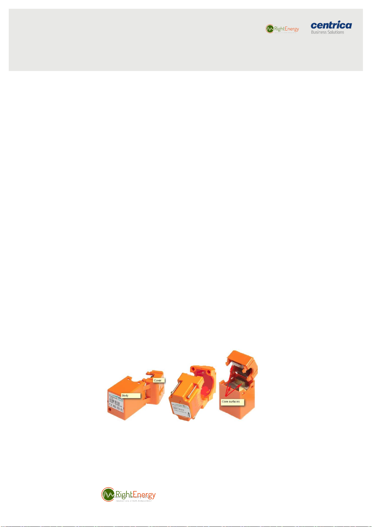
• 32A/63A , snapped-in cover.
• 225A, screwed cover.
The sensors are shipped closed, in order to protect the core from dust and
other pollutants. Open a sensor only when preparing to install it.
Figure 1. 32A/63A Figure 2. 225A Figure 3. Core
The sensor comes with a label fixed on it, containing a unique ID.
Page 7
Revision 1.4 January 2018
© 2018 Centrica plc. Registered office: Millstream, Maidenhead Road, Windsor, Berkshire. SL4 5GD.
Registered in England & Wales No 3033654
7
PAN-10 and PAN-12 Sensor installation guide
Mapping the site
See ‘Panoramic Power deployment guide’.
Installing a sensor
This process is divided into two stages:
1. Physically attaching the sensors to the circuit wires;
2. Registering the installation in Panoramic Power System.
Attaching the sensors to the circuits
To install a sensor, follow these steps:
1. Open the cover of the electrical panel board.
2. Make sure you have a plan that indicates the circuits to be monitored
and the sensor IDs associates with each such circuit. Identify the circuit
breaker on which you would like to install the sensor.
The ID appears on the label fixed to the sensor.
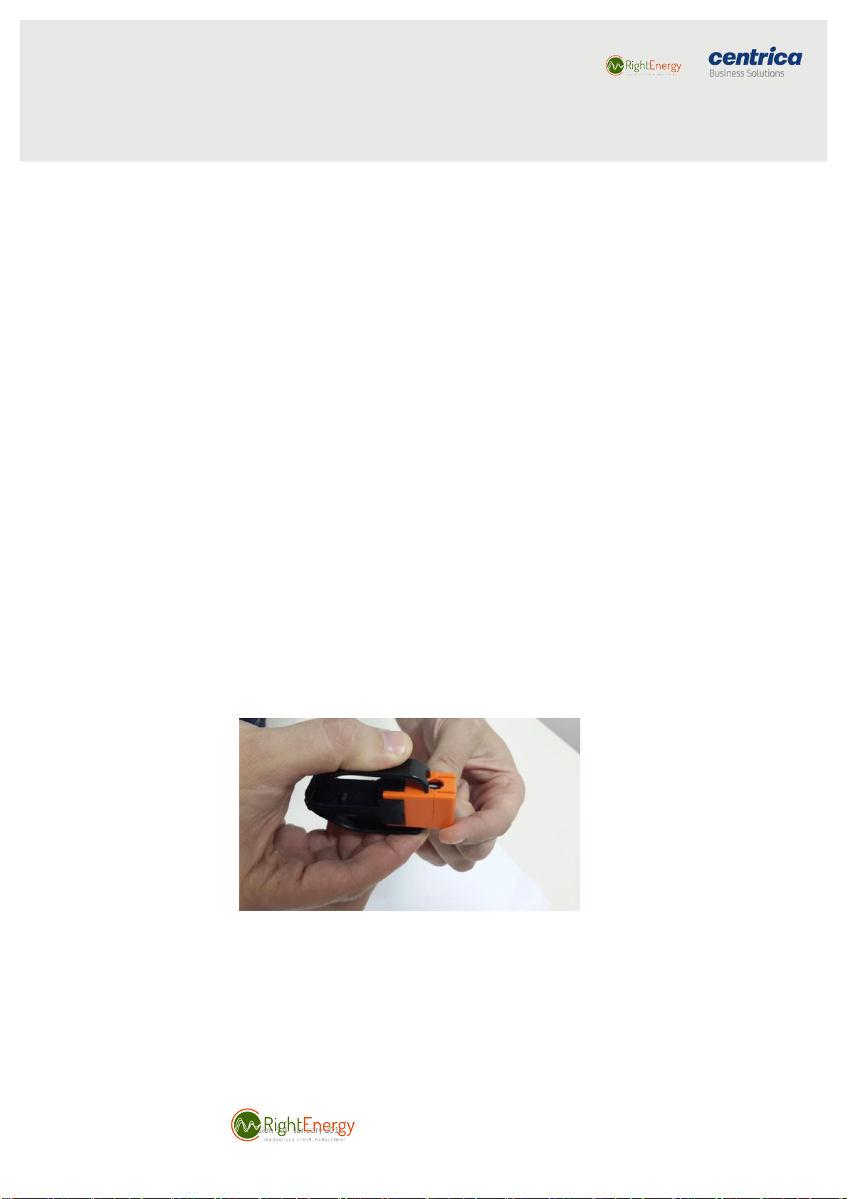
3. Pick a sensor and slide the opener into position from the labeled side
towards the cover.
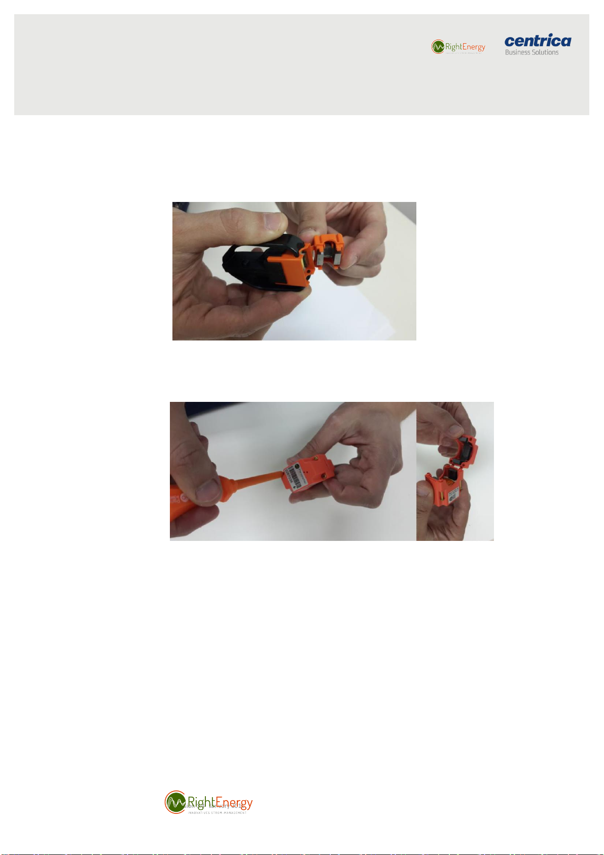
4. Snap the opener's pins into the four holes (in 225A unscrew the cover).
Figure 4. Slide opener into position
Page 8
Revision 1.4 January 2018
© 2018 Centrica plc. Registered office: Millstream, Maidenhead Road, Windsor, Berkshire. SL4 5GD.
Registered in England & Wales No 3033654
8
PAN-10 and PAN-12 Sensor installation guide
5. Press the two sides of the opener to release the sensor cover.
Figure 5. Press the opener to release the cover.
6. Open the four screws.
7. Make sure the four core surfaces are free of dust or any other particles.
If necessary, wipe it with a dry cloth
Note Whenever possible, avoid installing the sensor behind wires and position it
at the front of the panel board.
8. Place the opening of the sensor on a clean section of the electrical cable
with the arrow on the label pointing towards the load, so that the sensor
ID and barcode are visible and easily readable.
9. Close the sensor cover, snapping it into its place (in 225A screw back the
cover) and making sure that all four pins are properly inserted and the
sensor is tightly closed.
10. You can learn more about sensors installation in this video clip.
Page 9

Revision 1.4 January 2018
© 2018 Centrica plc. Registered office: Millstream, Maidenhead Road, Windsor, Berkshire. SL4 5GD.
Registered in England & Wales No 3033654
9
PAN-10 and PAN-12 Sensor installation guide
Registering the installed sensor
See ‘Panoramic Power deployment guide’.
Post installation troubleshooting
If the sensor vibrates after installation (you can hear the vibration noise or feel
it when touching the sensor), it means that the sensor is not properly closed.
Try to press the two parts of the sensor or tighten the screws to close it tightly.
If the vibration persists, open the sensor and reinstall it or try using another
sensor.
Monitoring sensor activity
See ‘Panoramic Power deployment guide’.
Uninstalling a sensor
Open the sensor in the way you first opened it and remove it from the cable.
Page 10

Revision 1.4 January 2018
© 2018 Centrica plc. Registered office: Millstream, Maidenhead Road, Windsor, Berkshire. SL4 5GD.
Registered in England & Wales No 3033654
10
PAN-10 and PAN-12 Sensor installation guide
Sensor specifications
Specifications
PAN-10
PAN-12
Physical dimensions
17 x 20 x 32 mm
0.67 x 0.79 x 1.26 inch
46.2 x 22.8 x 32.6 mm
1.82 x 0.90 x 1.28 inch
Max hot-air outer diameter
(including insulation)
7 mm
0.28 inch
18.8 mm
0.74 inch
Current measurement
range
0-63 A
0-225 A
Current measurement
accuracy (typical, at 25° C)
<2% at I>1A
<2% at I>10A
Minimum operating current
0.3 – 0.45 A
0.5 – 0.8 A
AC frequency supported
50 Hz (EU, JPE)
60 Hz (US, JPW)
50 Hz (EU, JPE)
60 Hz (US, JPW)
Transmission frequency
434 MHz (EU)
902-928 MHz (US)
923 MHz (JPE, JPW)
434 MHz (EU)
902-928 MHz (US)
923 MHz (JPE, JPW)
Transmission power (ERP)
0 dBm (Max)
-4 dBm (Max JPE, JPW)
0 dBm (Max)
-4 dBm (Max JPE, JPW)
Transmission interval
10 seconds
10 seconds
Safety and
EMC certificates
USA & Canada
Safety: UL-61010-1,
CSA-C22.2 (ETL listed)
EMC/Radio: FCC Part 15
subpart B, C
Europe
Safety: EN-61010-1 (CE)
EMC: EN-ETSI 301489-3,
Radio: EN-ETSI 300220-1
Japan
Radio: ARIB STD-T108
USA & Canada
Safety: UL-61010-1,
CSA-C22.2 (ETL listed)
EMC/Radio: FCC Part 15
subpart B, C
Europe
Safety: EN-61010-1 (CE)
EMC: EN-ETSI 301489-3,
Radio: EN-ETSI 300220-1
Japan
Radio: ARIB STD-T108
Flammability rating of
external enclosure
UL94 V-0
UL94 V-0
Operating temperature
0-50° C
0-50° C
Storage temperature
-20-65° C
-20-65° C
Page 11

Revision 1.4 January 2018
© 2018 Centrica plc. Registered office: Millstream, Maidenhead Road, Windsor, Berkshire. SL4 5GD.
Registered in England & Wales No 3033654
11
PAN-10 and PAN-12 Sensor installation guide
Troubleshooting
If you encounter a problem, first try the following solutions:
Problem
Solution
The sensor is vibrating
Make sure that the sensor is completely
closed (all four pins/screws are in place).
If they are, try pressing the sensor again
like you did when closing it.
The sensor is not sending measurements
Make sure the circuit has current.
Make sure that the sensor arrow points
in the direction of the load.
Make sure the sensors are near enough
to the bridge for the bridge to receives
its signals.
Check the reception LED of the bridge.
If it is not blinking it means that it is
not receiving signals.
 Loading...