

Page 1

INSTALLATION MANUAL
Page 2

Page 3

CENTRAL®VAC BRAND BUILT-IN VACUUM SYSTEMS
INSTALLATION MANUAL
Table of Contents
Introduction ............................................................................................................4
Planning Tips ........................................................................................................4
Planning and Installation Overview........................................................................4
Safety Rules ..........................................................................................................4
Tools ......................................................................................................................5
Materials ................................................................................................................5
Planning the Installation ........................................................................................6
Planning the Tubing System..................................................................................7
Tubing System Planning Examples ......................................................................9
Installing the Tubing System................................................................................10
Installing the Power Unit ......................................................................................12
Installing Inlet Valves in Existing Homes ............................................................15
Installing Inlet Valves in New Construction..........................................................20
Alternative Installation Ideas................................................................................21
Copyright © 2010 CentralVac International. All Rights Reserved.
PO Box 259 T (800) 666-3133
23455 Hellman Ave. www.centralvac.com
Dollar Bay, MI 49922 F (906) 483-4058 [email protected]
Page 4
Introduction
Planning and Installing Your CentralVac Built-In Cleaning System
The CentralVac Built-in Cleaning System is designed and built for
years of use. Protect your investment by reading these instructions all
the way through. This will give you a basic understanding of the system
and you will know what to look for as you plan and complete your
installation.
You can install the system yourself if you have some remodeling or construction experience. A typical installation takes about one weekend. If
you are ever in doubt about part of your installation, contract with a professional.
Planning Tips
The secret to a successful installation is planning. Plan everything on
paper before you start cutting holes in your walls.
You should check the entire home, noting wall and basement construction details, such as joist direction, location of heating ducts, plumbing,
etc. This will help you determine the best path for the tubing system
and the best location for the power unit. Tubing can run overhead, in
the basement, and up into partition walls to inlet valves. It can also run
inside a wall to a crawl space or attic, and from this point over to
partition walls and down to the inlet valves.
Use a map wheel where blueprints (w/scale) are available.
One final tip to remember when planning, you can never have a power
unit that is too big, or have too many inlets in your home!
Planning and Installation Overview
1. Determine the location for the Power Unit and
Canister.
2. Determine the locations for the Inlet Valves.
3. Determine the location and path for the Tubing
System.
4. Gather the tools and materials.
5. Install the Power Unit and Canister.
6. Install the Inlet Valves.
7. Install the Tubing System.
8. Test the System.
Safety Rules
l Protect your eyes whenever you are working around power tools
and construction debris - Wear Safety Glasses.
l Be careful when drilling to check for electrical wiring and
plumbing.
l Check your local Building Code for any regulations governing any
of the phases of your installation.
l Use common sense.
l If you are in doubt about any portion of the installation, call a
professional to have it done for you.
Warning
Before drilling any holes or making cuts in walls or
floors, take extreme care to determine the locations
of electrical wires, plumbing or other obstructions
that could create a hazard.
- 4 - (800) 666-3133CentralVac International
Page 5
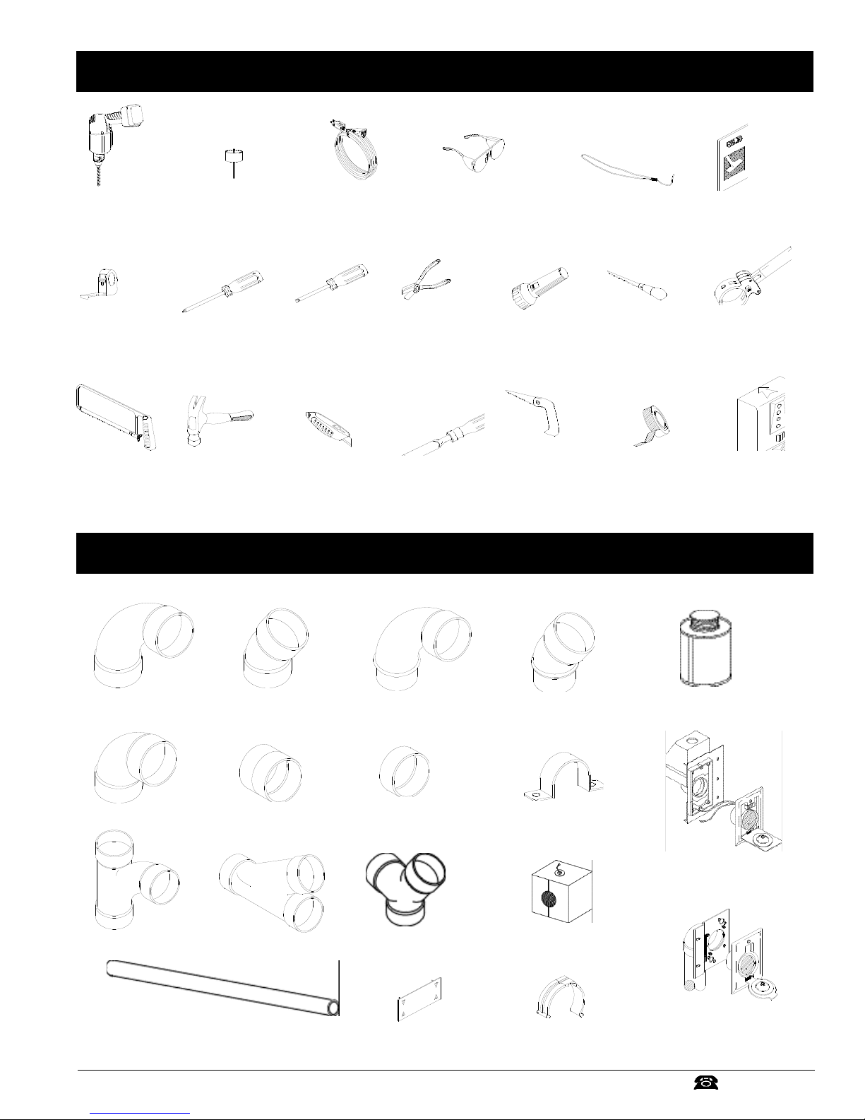
Tools
½” Electric Drill
Masonry Drill Bit
Steel Tape
Measure
Hacksaw or
Small Handsaw
Note: We recommend the 1/2" Dewalt Right Angle Drill #DW-124 and the Milwaukee 2 9/16" Self Feeding Bit #48-25-2561 for drilling tubing holes.
2¼” Hole Saw
or Cutter
Screw Driver
(Phillips)
Hammer Utility Knife Wood Chisel
Extension Cord
Minimum 14 Gauge
Screw Driver
(Common Blade)
Wire Cutters
Safety Glasses
Flashlight Drywall Saw
Metal Coat Hanger
Long Pilot Hole Drill
(made out of a metal
coat hanger)
Electrical Tape Stud SensorKeyhole Saw
Mounting Bracket
Template
Plastic Pipe
Cutter
Materials
90oSweep Ell
90oShort Ell
90oSweep Tee
2” Plastic Pipe
45oEll
Stop Coupler Pipe Cap
45oSingle Wye
CentralVac International
90o Street Ell
45oDouble Wye
Stud Guard
- 5 -
45o Street Ell
Plastic Pipe Strap
Low Voltage Wire
Low Voltage
Wire Clip
Plastic Pipe Cement
Direct Connect
Inlet Valve &
Mounting Bracket
Inlet Valve
& Mounting Bracket
(800) 666-3133
Page 6
Planning the Installation
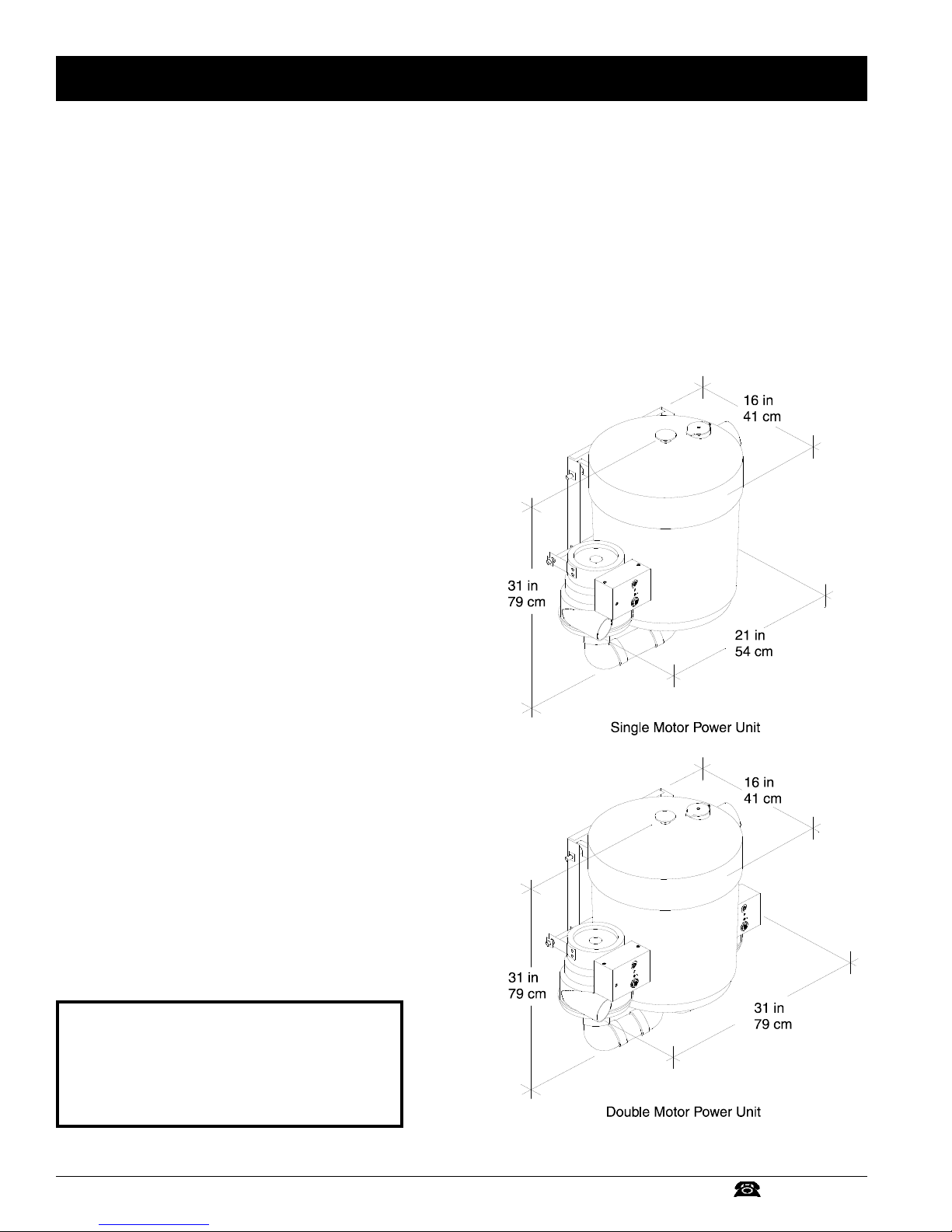
Determine the Size of the Power Unit
There is not a simple formula for choosing the correct size power unit
for your cleaning system. If you live in a high altitude area (5,000 to
7,000+ ft. above sea level), you may need to move to the next larger
size power unit, or go with a double motor unit.
Remember, you can never have a power unit that is too big, or have
too many inlets in your home!
Area to be Cleaned (sq. ft.) ............Recommended Power Unit
7,000+ ............................................CVS-16DP
up to 7,000 ......................................CVS-11DP
up to 6,000 ......................................CVS-07DP
up to 5,000 ......................................CVS-16
up to 4,000 ......................................CVS-11
2,000 or less ..................................CVS-07
Determine the Location of the Power Unit
The power unit and canister will mount in the basement,
garage, utility room, or other remote area, preferably on a
firm, outside wall away from heat-producing units, such as a
boiler, water heater, dryer, etc.
l Locate the power unit away from the general living
area.
l Do not install the power unit in the attic.
l Do not locate the power unit close to a source of
extreme heat (i.e., water heater) or in an area with
high ambient temperature (i.e., attic, furnace room).
l It is important that you also plan the installation of an
exhaust tube to the outdoors if ventilation is not
adequate. It is usually best to exhaust out the rear of
the house avoiding patios, windows, and entrance
areas.
l Locate the power unit in an accessible area for ease in
changing the paper bag filter and periodically cleaning
the cloth bag filter.
l Locate the power unit within 4 feet of a grounded elec-
trical outlet. The power unit requires a 120 VAC power
source with sufficient capacity to service the unit.
l Do not use extension cords.
l If the power unit is located in a closet or a small utility
room, make sure the area is well-ventilated (i.e., with
door louvers).
l The power unit has an auxiliary inlet for a garage,
basement, utility room, etc. However, installing a
separate inlet is the preferred method. It is more
convenient to use a hose with an inlet valve which
uses a low voltage control circuit to start and stop the
power unit automatically, than to use the auxiliary inlet
which must be switched on and off manually.
WARNING
THE POWER UNIT MUST NOT BE MOUNTED
IN A HIGH AMBIENT TEMPERATURE AREA
SUCH AS ATTIC, FURNACE ROOM, ETC. IF
NECESSARY, PLEASE CONSULT FACTORY.
- 6 - (800) 666-3133CentralVac International
Page 7
Planning the Installation
Determine the Locations of the Wall Inlets
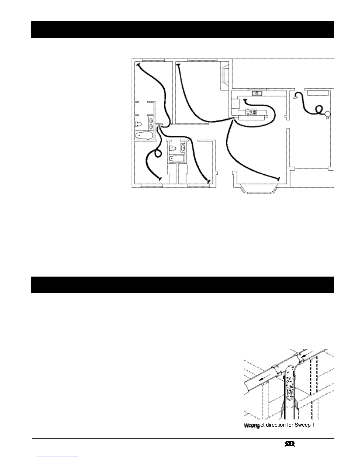
Inlets are usually located centrally in the
house in hallways, near doorways and near
the bottom of stairways. It is important to
overlap areas covered from each inlet valve to
assure thorough cleaning of the entire home.
Inlet valves placed in halls and near doorways
provide the maximum amount of cleaning
coverage from the minimum number of valves
frequently making it possible to clean three or
four rooms from one inlet. Valves in these
locations are seldom if ever obstructed by
furniture placement. An inlet located near the
bottom of the stairway permits easy,
convenient cleaning of the stairwell and surrounding areas.
l Start with the area of the house farthest
from power unit and tentatively select an
inlet location that will provide maximum
cleaning coverage.
l If possible, locate the inlet close to an electrical outlet, to be able
to use electric power heads.
l Using a 30 foot length of cord, check to be sure all adjacent areas
of the house can be cleaned from this location.
l Allow sufficient slack in cord to provide for furniture placement
and wall offsets. Be certain all areas can be cleaned including
walls and ceilings.
Planning the Tubing System
Airflow Rules
l 90oSweep Tees should always be installed in the direction of air
flow toward the power unit.
l 90oSweep Tees should never be installed with the sweep pointing
down, because the dirt will fall to a lower level, and not be carried
to the power unit.
l 90oShort Tees should be installed only on inlet valves.
l Use no more material (tubing, fittings, etc.) than is necessary. Less
tubing and fittings means more performance.
l It is important to have a sealed system. Cut and glue your pvc
joints carefully.
l The total distance from the power unit to the furthest inlet should
be less than 200’.
l The length of the exhaust pipe should be less than 30’.
l A slight amount of slope toward the power unit will help your
system carry dirt and debris and avoid plugs.
l Mark the location of the first inlet valve and proceed toward the
power unit, locating additional inlet valves until all parts of the
house can be comfortably reached with the hose.
It is preferable to plan on using wall inlets, however, the same inlet can
be placed in the floor if tubing cannot be installed in the wall. Wall
inlets should be installed to match the height of electrical outlets.
l Use only CentralVac 2” plastic pipe. Do not use any other type.
CentralVac plastic pipe is much thinner and lighter, .06” wall
thickness, and is designed for vacuum applications.
l A branch line located directly below an overhead trunk line will
accumulate dirt due to the effects of gravity. The result will be a
pile of dirt at the base of the inlet valve every time it is opened.
CentralVac International
- 7 -
(800) 666-3133
Page 8
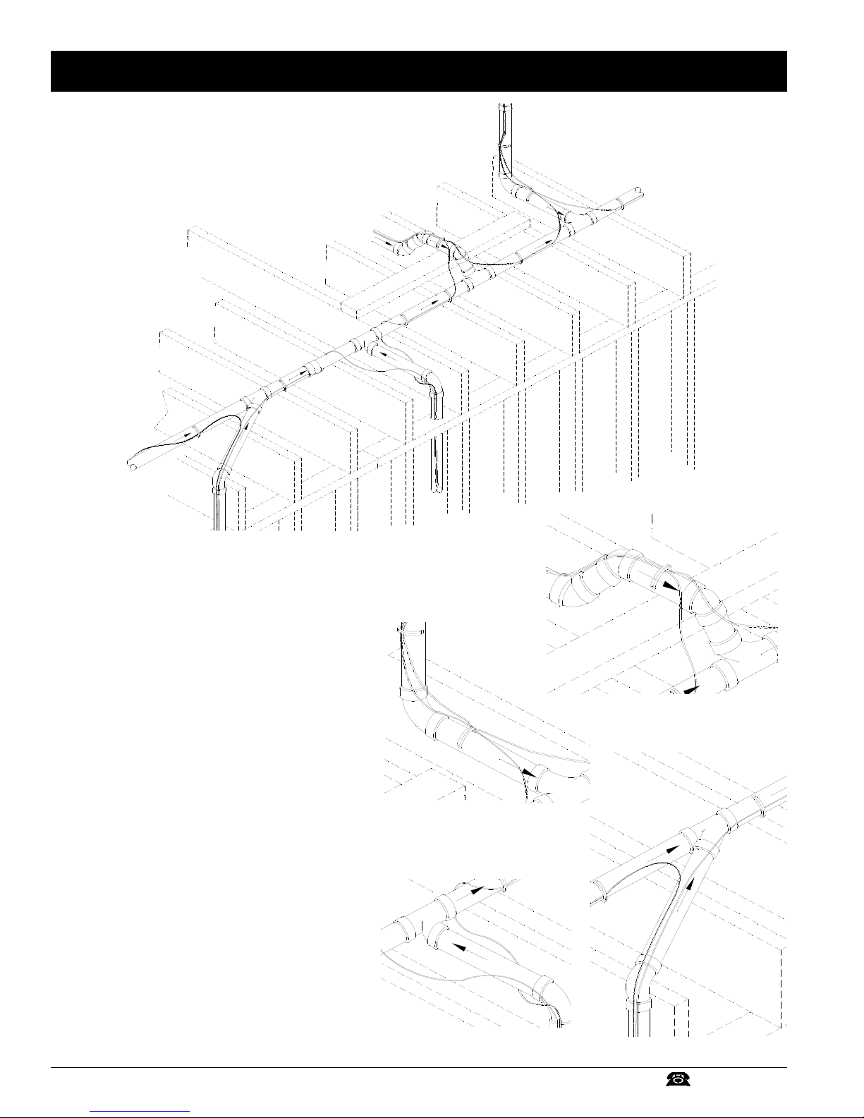
Planning the Tubing System
The amount of airflow that reaches the hose is dependent on the
efficiency of the layout of the tubing system. Lines are to be kept
as straight as possible.
The Trunk Line
The trunk line connects the furthest inlet valve to the power unit.
All other inlet valves will be serviced by branch lines flowing into
the trunk line. If the basement is unfinished, the trunk line is best
run beneath the joists in the basement ceiling. The upper floors
can be serviced through closets, cold air return ducts, or in
partition walls. The trunk line could also run straight up to the
attic and service the floors beneath by branch lines dropping
through closet ceilings or partition walls. The location of the trunk
line will greatly depend on the construction of the house and the
location of the power unit.
Branch Lines
Branch lines join the remaining inlet valves to the trunk line. As
with the trunk line these lines should be kept as straight as
possible. Forty-five degree fittings should be used to avoid sharp
corners when possible. Airflow direction should always be
considered when installing branch lines.
A branch line located directly below an overhead trunk line will
accumulate dirt due to the effects of gravity. The result will be a
pile of dirt at the base of the inlet valve every time it is opened.
To avoid this situation the illustrated techniques should be used.
- 8 - (800) 666-3133CentralVac International
Page 9
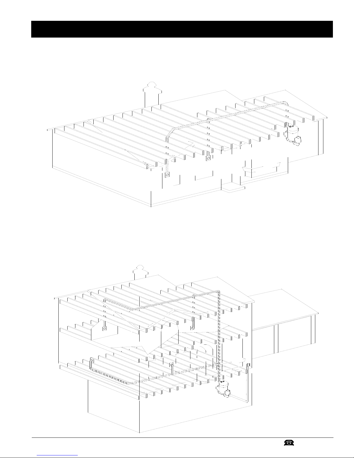
Tubing System Planning Examples
The Ranch Style House
Here the power unit is mounted in the garage. The intake and exhaust tubing, the only exposed tubing in the installation, runs up the garage wall
and into the attic. The trunk line runs horizontally through the attic from the power unit to the farthest inlet location, branch lines spread throughout
the attic, connecting the trunk line to the inlet tubing. Each inlet tube is threaded vertically through an inside wall. The inlets located in hallways,
next to doorways, and in large rooms, provide maximum access to all cleaning areas.
The Two or Three Story House
In this installation, the power unit is mounted in the basement, conveniently located for shop use and messy cleaning jobs. The intake tubing runs
up the basement wall and connects to the main trunk line, which runs along the unfinished basement ceiling. Two first-floor inlets are connected to
the trunk line by vertical inlet lines run through interior walls. In the center of the house, a vertical branch line runs from the basement trunk line,
through stacked closets, up into the attic. A second trunk line runs across the attic and two branch lines connect to inlet lines, which are dropped
down through upstairs interior walls.
The double-trunk line system is commonly used in two or three story houses. Finding the “Key” to an accessible vertical area is the most important
step in this kind of installation.
CentralVac International
- 9 -
(800) 666-3133
Page 10
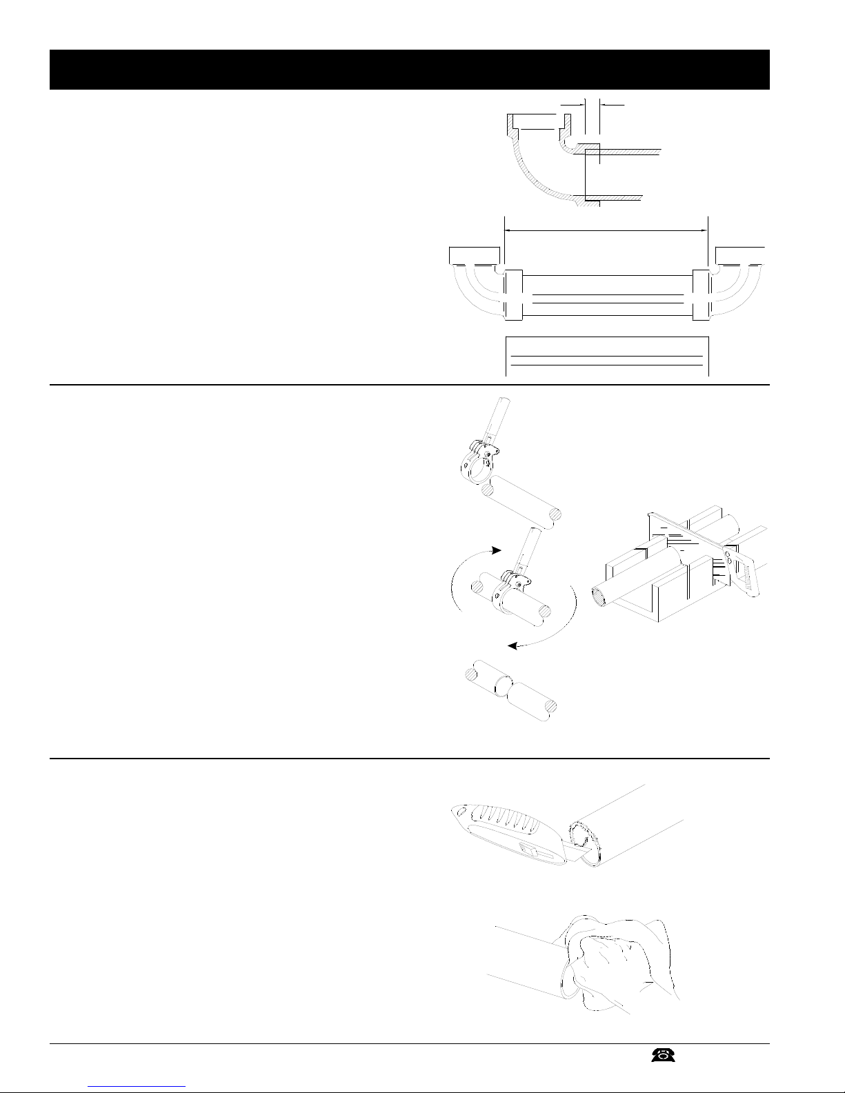
Installing the Tubing System
Cutting and Cementing PVC Tubing
and Fittings
Measure Twice, Cut Once
1. Measuring: Measurements should be taken from the base of the
pipe-stop on the inside of the fitting hub when sizing tubing. As
each section of tubing is cut, it should be dry fitted before the next
measurement is taken.
2. Cutting: The tubing should be cut as straight and square as
possible. A plastic pipe cutter or a miter box can be used. All rough
edges must be removed with a utility knife or coarse sandpaper.
3. Dry Fitting: Once all the pieces are cut they should be dry fitted to
check for correct fit. The markings on the fittings can be utilized to
assure proper alignment.
4. Cleaning: Before gluing, both the tubing and the fitting must be
free of plastic burrs, dirt and grime. The components should be
wiped with a clean cloth if necessary.
- 10 - (800) 666-3133CentralVac International
Page 11
Installing the Tubing System
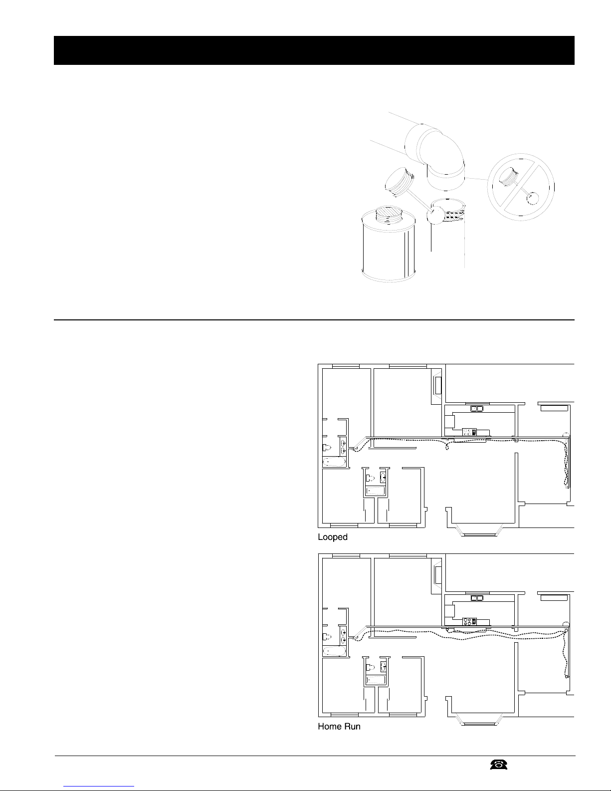
5. Gluing: Plastic pipe cement actually welds the fitting to the
tubing. A chemical reaction permanently joins the molecules from
each surface to produce an airtight seal.
6. Plastic pipe cement should be applied only to the tubing. Cement
applied to the fitting will be pushed ahead and create a rough
bead on the inside of the fitting. This bead will reduce airflow and
could cause a clog.
7. The tubing should be inserted all the way into the fitting and
twisted a quarter turn to evenly distribute the cement.
8. All excess cement should be removed with a rag. The joint is
ready for handling in 15 minutes. The cement should be allowed
to set for at least four hours before the vacuum system is used.
Low Voltage Wire
One of the greatest benefits of a central vacuum system is that the
power unit is turned on and off at the inlet valve. The power unit is
activated at the inlet valves by simply inserting the hose into the inlet
valve.
To facilitate this, low voltage wire must follow the tubing system. Each
inlet valve must be able to activate the machine independently of the
other valves. There must be an uninterrupted route from each inlet
valve to the power unit. The wire should be attached to the tubing with
a wire clamp at least every four feet.
There are (2) wiring methods which are acceptable, looped and home
run.
Looped: Set up wire spool at system location area. Pull wire through
drilled holes to the furthest inlet location. This is also your trunk line
path. Tie off on mounting plate. Start at the next furthest inlet to
system. Grab main wire line and pull over to inlet location through
drilled holes and tie off at mounting plate. Continue in this manner
until all inlets are wired.
Home Run: For each inlet, one piece of wire is run from each inlet to
the system location. If you have (3) inlets, then you will have (3) wire
ends to tie together at the system.
You can also do a combination of the two methods. The wire can be
pulled before, during, or after the pipe installation. The most popular
way seems to be before pipe installation in new construction and
during pipe installation in existing construction.
CentralVac International
- 11 -
(800) 666-3133
Page 12
Installing the Power Unit
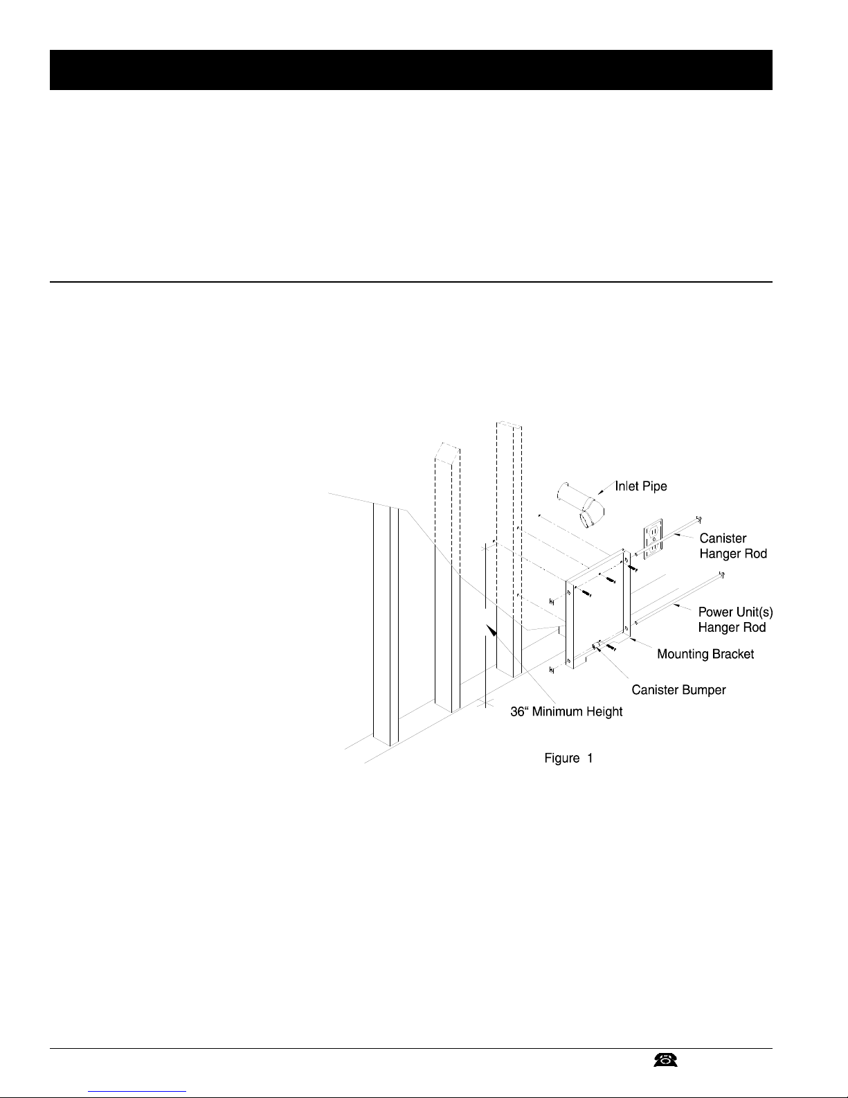
Each single & double motor power unit is provided with a mounting bracket and mounting hardware.
Included: Mounting bracket, canister hanger rod, power unit(s) hanger rod, wood screws, tinnerman nuts, PVC fittings and pipe (cut to size),
canister bumper.
1. Locate a wall stud at the desired vacuum system
power unit location, adjacent to an electrical
outlet if possible. If a wall stud is not available,
and the mounting bracket must be attached to
wallboard, use at least four holes in the
mounting bracket with suitable screws and
anchors to secure.
2. Level the mounting bracket and attach to
the stud using wood screws provided, or to
wallboard as described above. The recommended height from the floor to the top
of mounting bracket is 36 inches.
(Figure 1)
3. Slide a tinnerman nut on one end of
canister hanger rod approximately 1/2 inch
from the end. (Figure 1)
4. Slide the canister hanger rod through the
upper hole on one side of mounting
bracket, continue until rod projects
through the hole on the other side of
bracket. Slide a tinnerman nut on the end
of the rod to secure. (Figure 1)
5. Insert the power unit hanger rod through
the lower holes in the mounting bracket.
(Figure 1)
A) On single motor systems allow excess rod
length to project to the side where the power
unit is desired.
B) On double motor systems, center the hanger
rod in the mounting bracket.
- 12 - (800) 666-3133CentralVac International
Page 13
Installing the Power Unit
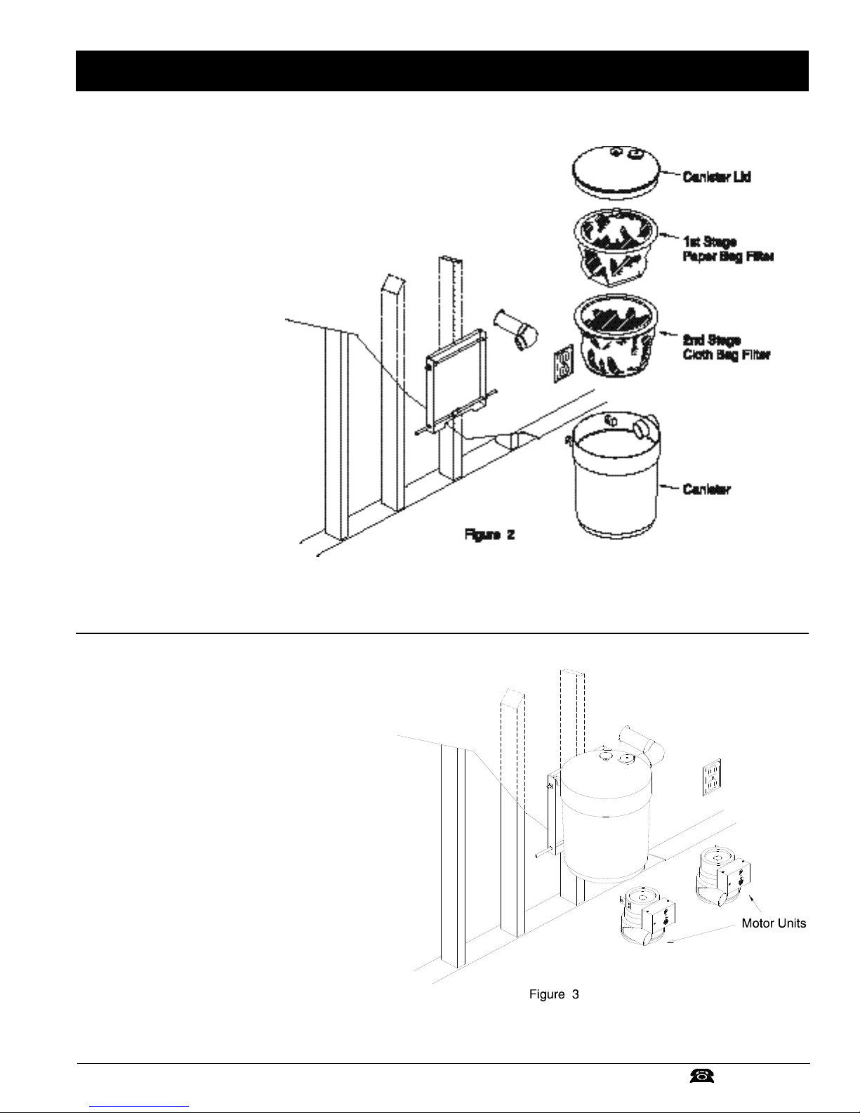
6. Slide the rubber bumper on
the power unit hanger rod.
Position the bumper in the
center of the rod so the
canister will rest on the
bumper. (Figure 2)
7. Place the 2nd Stage Cloth Bag
Filter, and the 1st Stage Paper
Bag Filter in the Canister.
Place the lid on the canister.
(Figure 2)
8. Hang the canister on the canister
hanger rod. (Figure 3)
CentralVac International
- 13 -
(800) 666-3133
Page 14
Installing the Power Unit
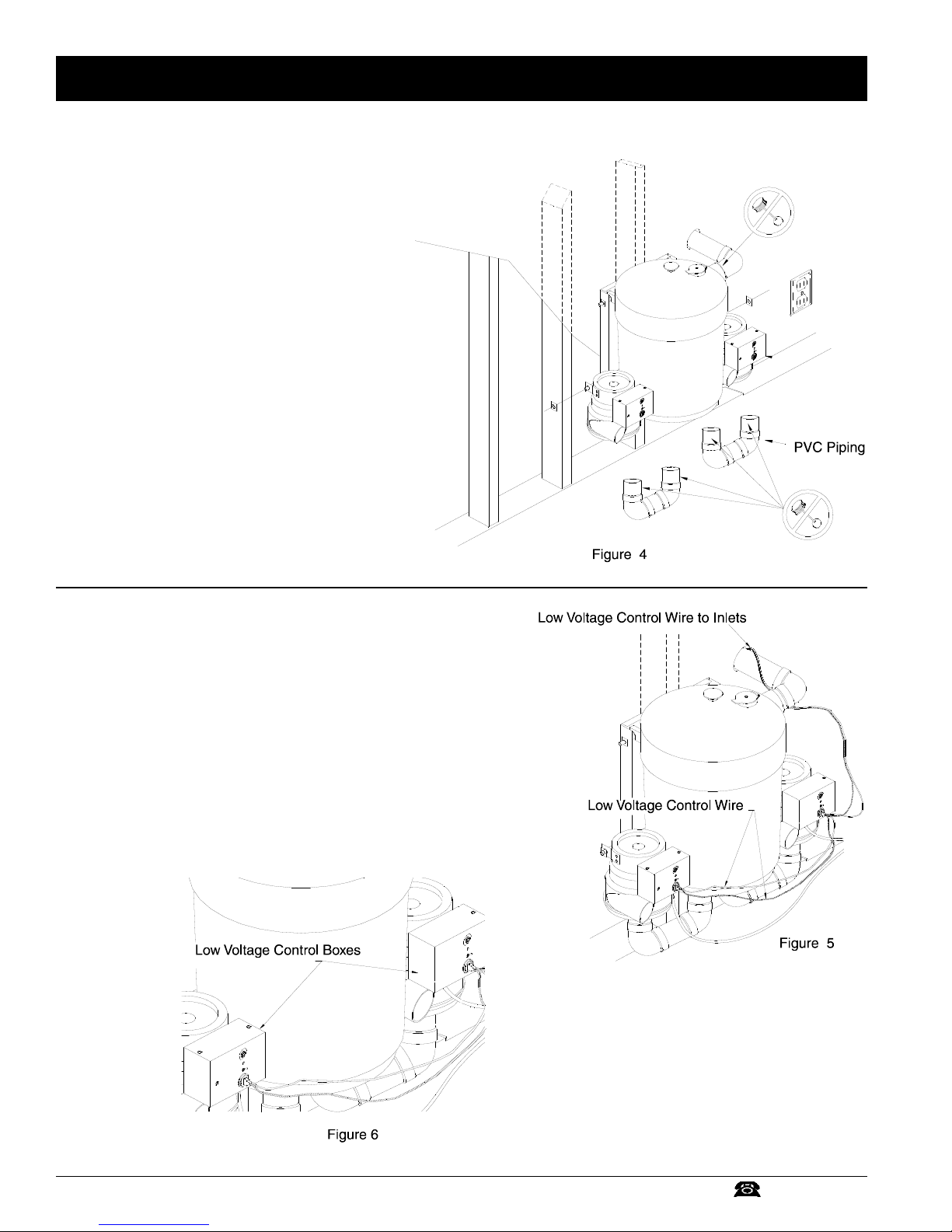
9. Slide on the power unit(s), and place
a tinnerman nut on each end of the
power unit hanger rod . (Figure 4)
10. Pipe the power unit to the canister
using the cut to size PVC pipe and
fittings provided.
Dry fit the parts before you glue
them.
Do not glue the fittings to the power
unit or the canister, this will make it
easier to repair or replace your
power unit.
A street ell (in & out) is fitted to the
canister inlet. A street ell is fitted to
the inlet of the power unit. (Figure 4)
11. Pipe the inlet pipe to the canister. Do
not glue the fittings or pipe to the
canister. (Figure 4)
12. Wire the low voltage control wire, taking care to keep the
polarity between the low voltage control box(s) as illustrated
in Figure 5 & 6. Left terminal to left terminal, right terminal
to right terminal. The low voltage control wire can be run
behind the canister.
n a double motor system: If the
power units run continually with no hoses plugged into
the system, and the manual vacuum motor switch is
turned off, reverse the low voltage control wire on one
of the low voltage control boxes.
- 14 - (800) 666-3133CentralVac International
Page 15
Installing the Power Unit
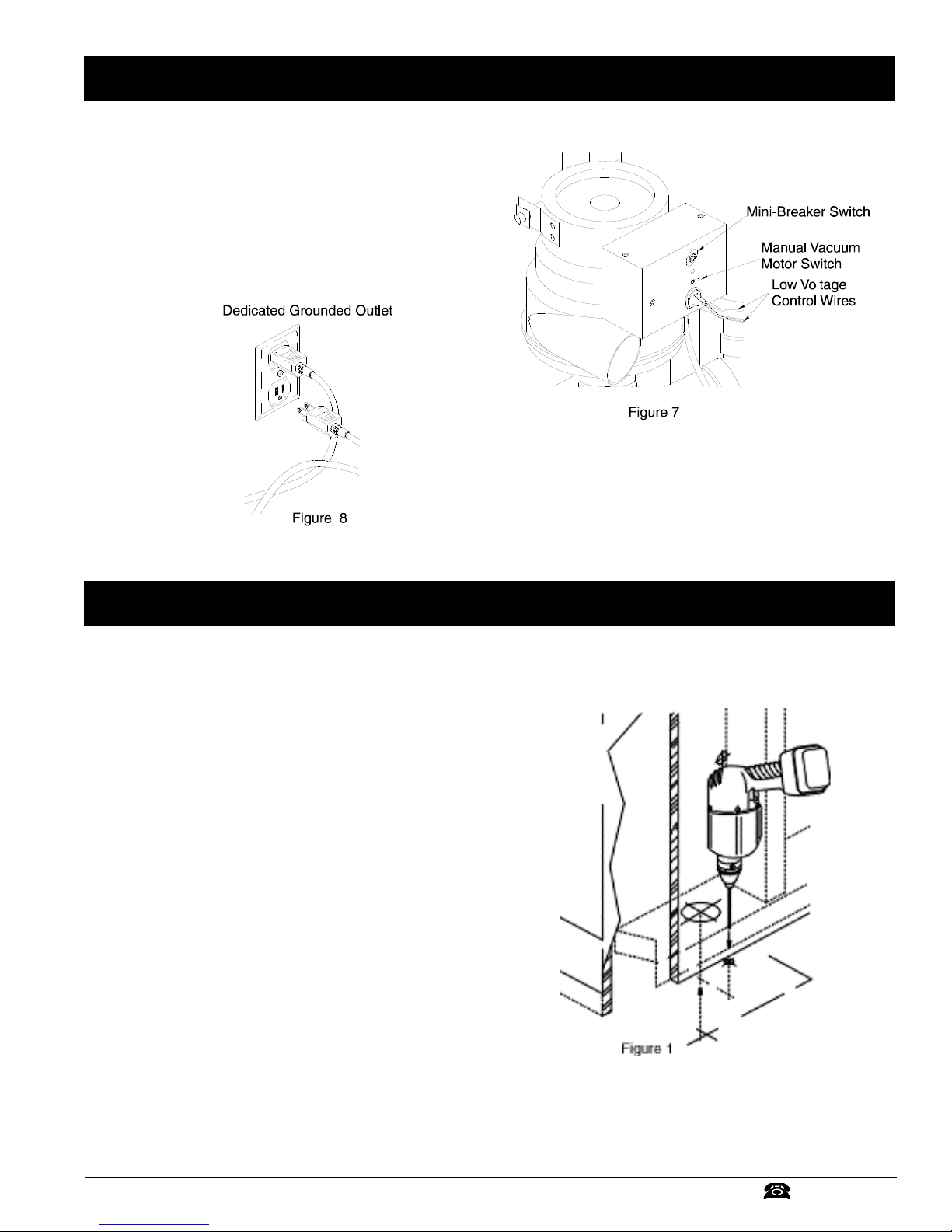
13. Plug the power unit(s) into a
dedicated grounded electrical
outlet(s). (Figure 8)
Installing Inlet Valves in Existing Homes
Installing Wall Inlets
1. Determine as closely as possible the desired location of the inlet
valve. You should use a stud finder or drill a ¾” inspection hole to
avoid drilling into the bottom of a stud or other “inner-wall” obstruction.
2. Drill a small pilot hole in the floor directly below the proposed
valve location. A straight length of coat hanger wire, cut at an
angle, makes a good pilot hole drill bit, but be careful not to snag
carpeting. Leave the pilot bit or a straightened length of coat
hanger wire through this pilot hole to serve as a locator and guide
point.
CentralVac International
- 15 -
(800) 666-3133
Page 16
Installing Inlet Valves in Existing Homes
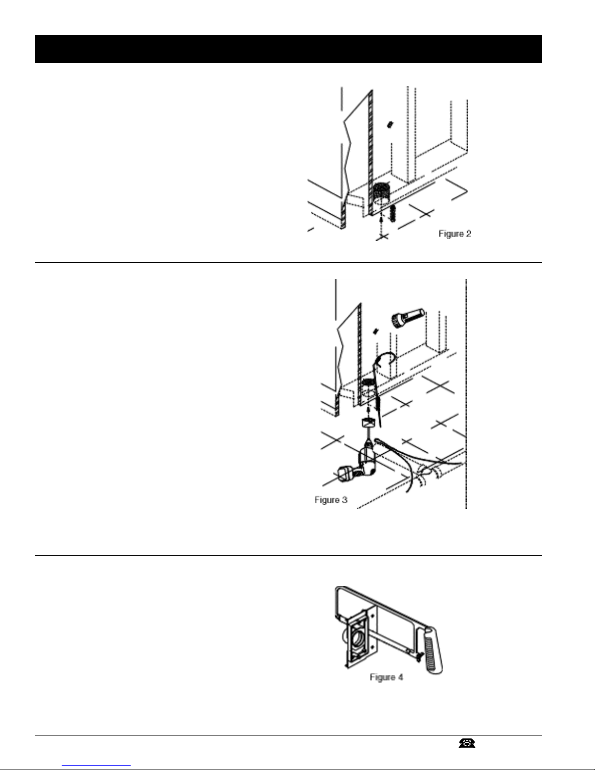
3. From beneath the floor, measure over
from the pilot hole to locate the center
of the sole plate.
4. Drill a 2 1/4” diameter hole through the
center of the sole plate. Using a
flashlight or probe, inspect the interior
of wall to be sure there are no obstructions.
Note: The opening you are going to cut in
the wall for the inlet valve should be
located between studs, clear of obstructions such as plumbing, wiring, heat
ducts, etc. Minimum stud width for
sufficient clearance for inner wall
mounting bracket assembly is 2 3/8”.
5. Cut the nailing tab off of the mounting
bracket with a hacksaw. If you are
going to install the inlet in the floor,
don’t cut the nailing tab off. You can use
the nailing tab to attach the mounting
bracket to the stud.
- 16 - (800) 666-3133CentralVac International
Page 17
Installing Inlet Valves in Existing Homes
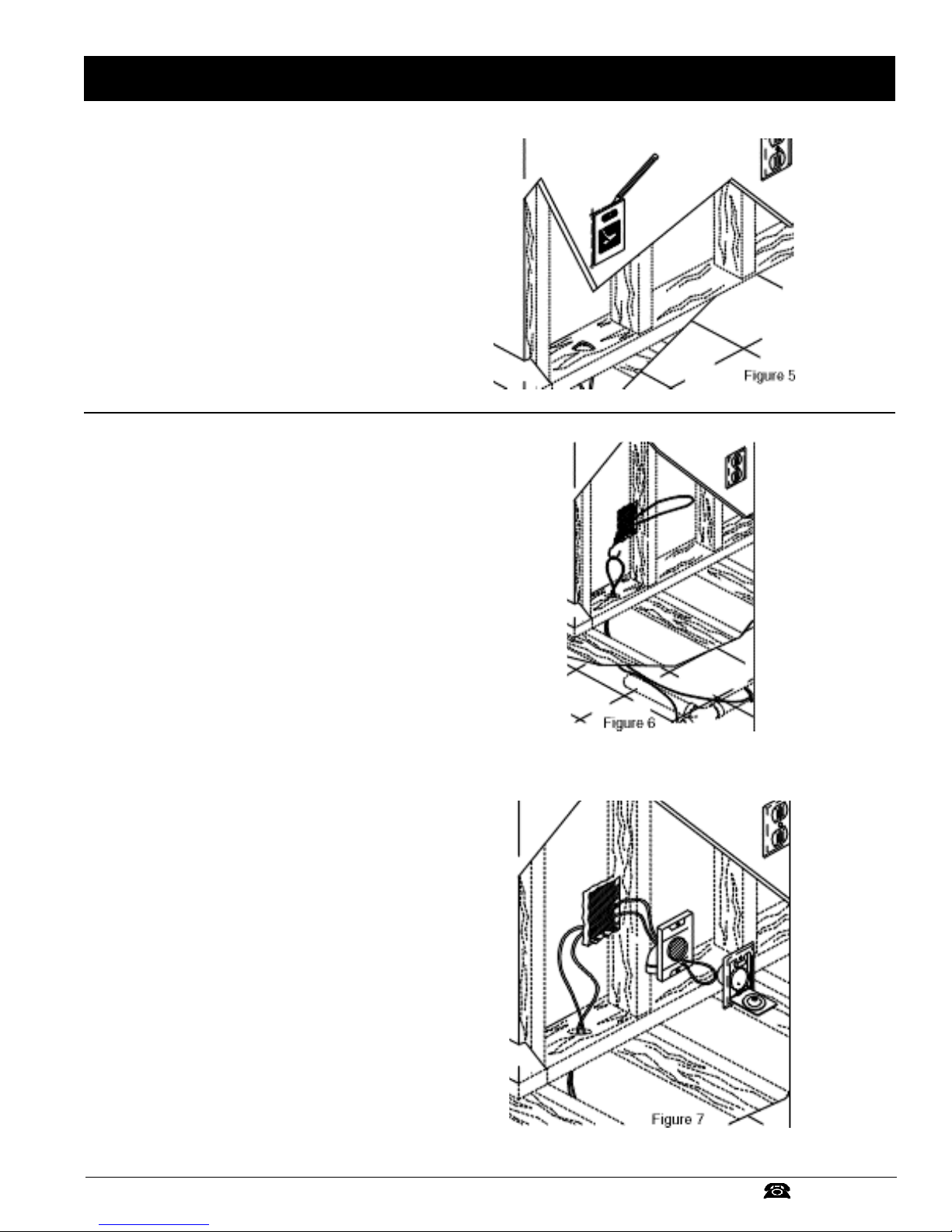
6. Use the mounting bracket template (or
the raised edge of the mounting
bracket) to trace an exact opening on
the wall (about the same height as an
electrical outlet).
7. Cut the horizontal cuts first, to be sure
there are no obstructions, with a
keyhole or drywall saw. Then cut the
vertical cuts.
Note: Be exact in cutting the opening as
there is very little overlap on the
mounting bracket.
8. Glue a 90oshort elbow to the mounting
bracket.
9. Feed a loop of low voltage wire from the
basement, you can use a coat hanger
to pull it up, and through the wire guide
hole on the mounting bracket.
CentralVac International
- 17 -
(800) 666-3133
Page 18
Installing Inlet Valves in Existing Homes
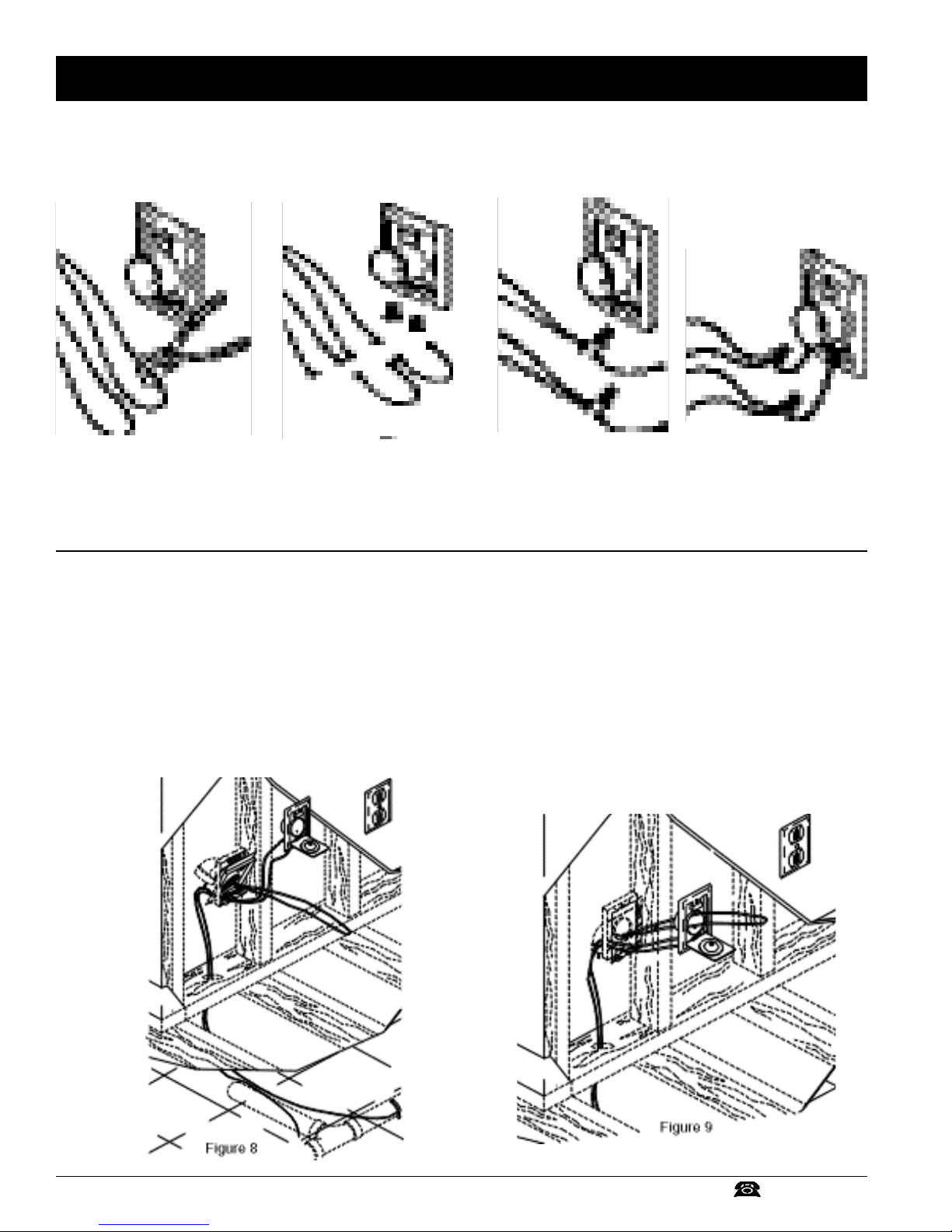
10. Strip the low voltage wire and wire it to the
inlet valve as shown.
11. Insert the assembled short elbow and mounting bracket through the wall cutout hole as illustrated. You can use a short bent length of coat
hanger to hold the assembly from dropping into the wall.
Wiring the Low Voltage Control Wires
12. Once the mounting bracket is completely inside wall cavity, pull the mounting bracket so that it fits the hole.
13. Push the inlet valve onto the short bent length of coat hanger wire and push it onto the mounting bracket.
Note: Mount the inlet valve so that it pulls down to open.
- 18 - (800) 666-3133CentralVac International
Page 19
Installing Inlet Valves in Existing Homes
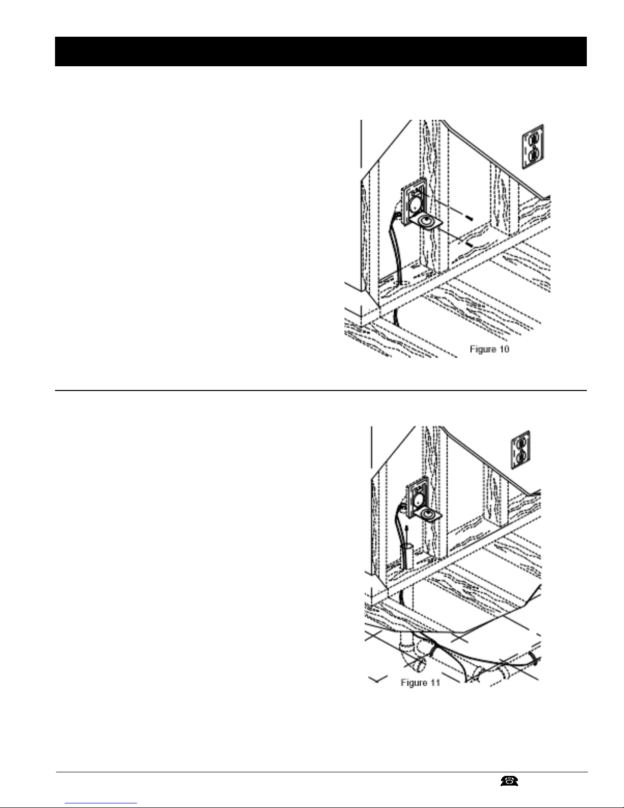
14. Insert and tighten the inlet valve
mounting screws to pull the assembly
together. Adjust the inlet valve for
perfect vertical alignment, and tighten
both inlet valve mounting screws.
15. Glue the outside of the end of the correct length of tubing and
push it up through the sole plate hole, into the short 90oelbow.
Twist the tubing as it makes contact to help guide it into the elbow.
CentralVac International
- 19 -
(800) 666-3133
Page 20
Installing Inlet Valves in New Construction
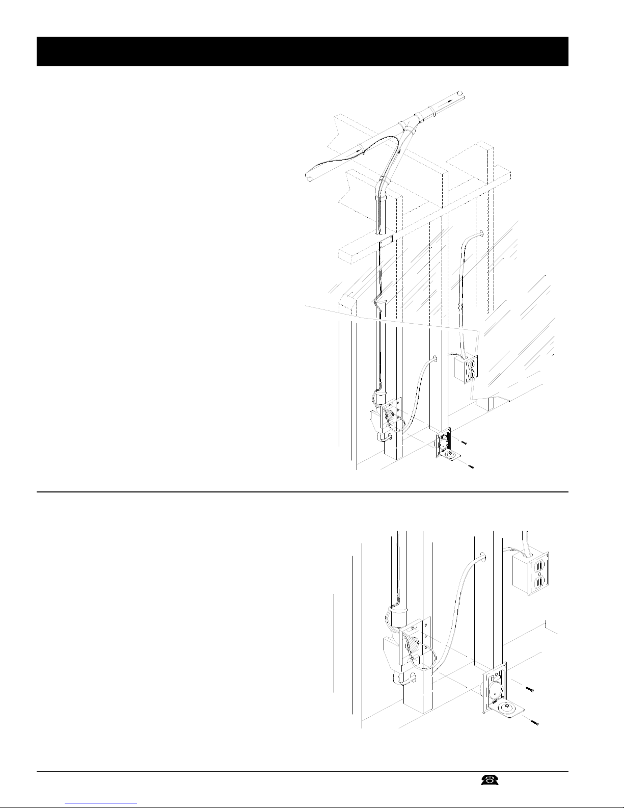
Wall inlet valves are easy to install in new construction before the
drywall is hung.
Before Drywall
1. Attach the mounting plate to the stud at the same height as the
electrical outlets.
2. Drill a 2 1/4” hole in the header plate, with the hole aligned with
the center of the mounting bracket.
3. Push the tubing through the hole in the header.
4. Glue the 90
5. Pull the low voltage wire, and clamp to the tubing with wire clips.
6. Put a nail guard on the header to protect from drywall screws
being driven into the installation.
7. If you are using a direct connect hose, have a qualified electrician
wire the 120 volt power.
8. Place a plaster guard over the mounting bracket.
o
short elbow into the mounting bracket and tubing.
After Drywall
9. After the drywall is finished, remove the plaster guard.
10. Wire the inlet valve to the low voltage control wire.
Note: Mount the inlet valve so that it pulls down to open.
11. Have a qualified electrician wire the 120 volt power.
12. Insert and tighten the inlet valve mounting screws to pull the
assembly together.
Adjust the inlet valve for perfect vertical alignment, and tighten
both inlet valve mounting screws.
- 20 - (800) 666-3133CentralVac International
Page 21
Alternative Installation Ideas
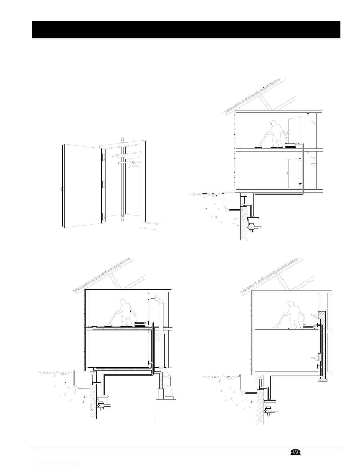
Through a Closet
If obstructions make it impossible to run vertical tube through partition
walls, the best and easiest alternative is to go through closets, particularly
when a closet on the second floor is directly above a closet on the main
floor. The tube will be exposed in the closet, but that may be the only way
to run pipe to the inlet.
You can install tubing coming up through the floor inside a closet, cold air
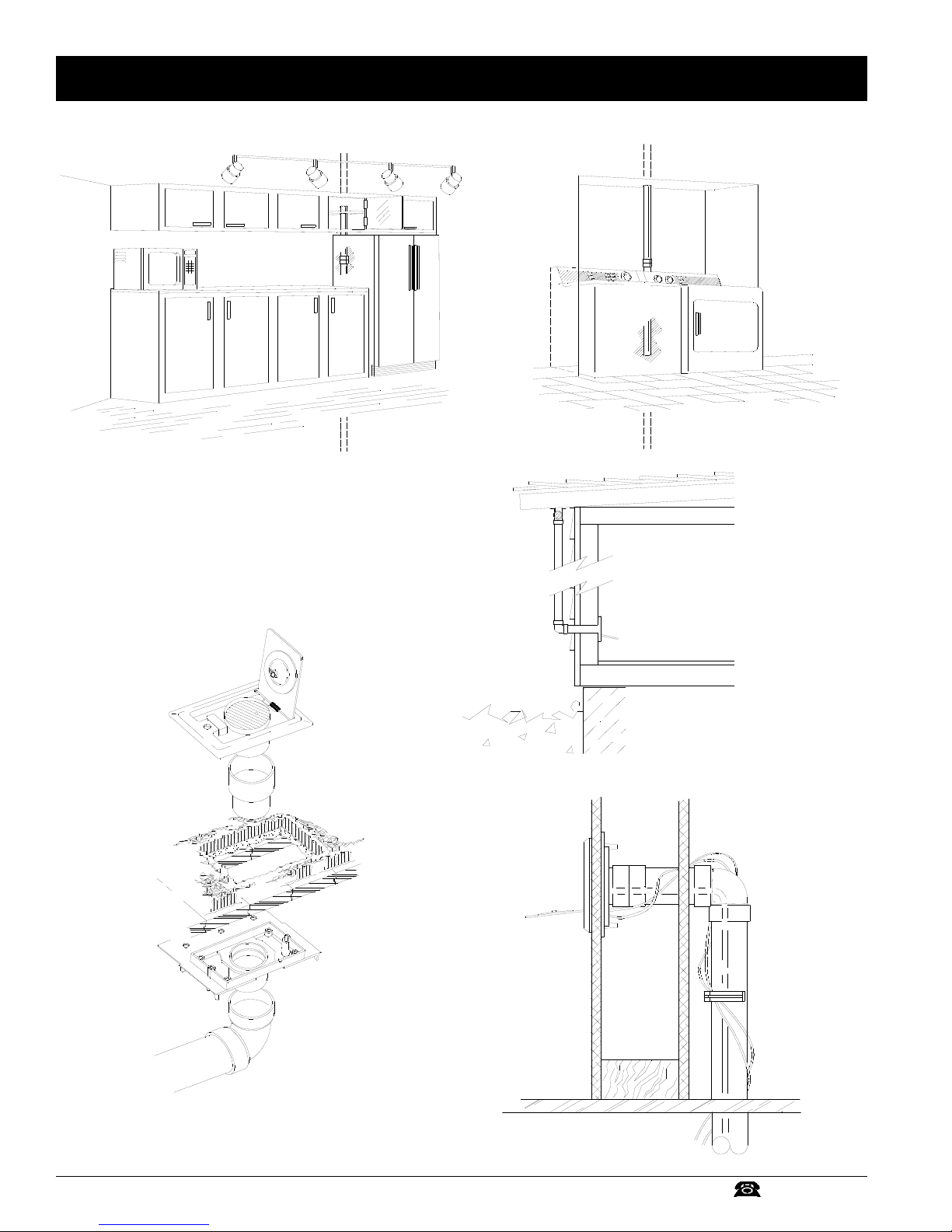
return, a laundry chute, or other access path. Be creative, there is usually
a way to get tubing to an inlet.
CentralVac International
- 21 -
(800) 666-3133
Page 22
Alternative Installation Ideas
- 22 - (800) 666-3133CentralVac International
Page 23

Page 24

The information in this manual is subject to change without notice. Please check www.centralvac.com for the latest information.
CentralVac International shall not be liable for technical or editorial errors or omissions contained herein; nor for incidental or consequential
damages resulting from the furnishing, performance, or use of this material.
This manual contains information protected by copyright. No part of this manual may be photocopied or reproduced in any form without prior
written consent of CentralVac International.
Copyright © 2010 CentralVac International. All Rights Reserved.
Revision Date: 03-01-10
PO Box 259 T (800) 666-3133
23455 Hellman Ave. www.centralvac.com
Dollar Bay, MI 49922 F (906) 483-4058 [email protected]
 Loading...