

Central Pneumatic CentralPneumatic 69269 Owner's Manual & Safety Instructions
Page 2 For technical questions, please call 1-888-866-5797. Item 69269
SAFETY OPERATION MAINTENANCESETUP
Table of Contents
Safety ......................................................... 2
Setup .......................................................... 6
Specifications ............................................. 6
Operation ................................................... 10
Maintenance .............................................. 12
Parts List and Diagram .............................. 14
Warranty .................................................... 16
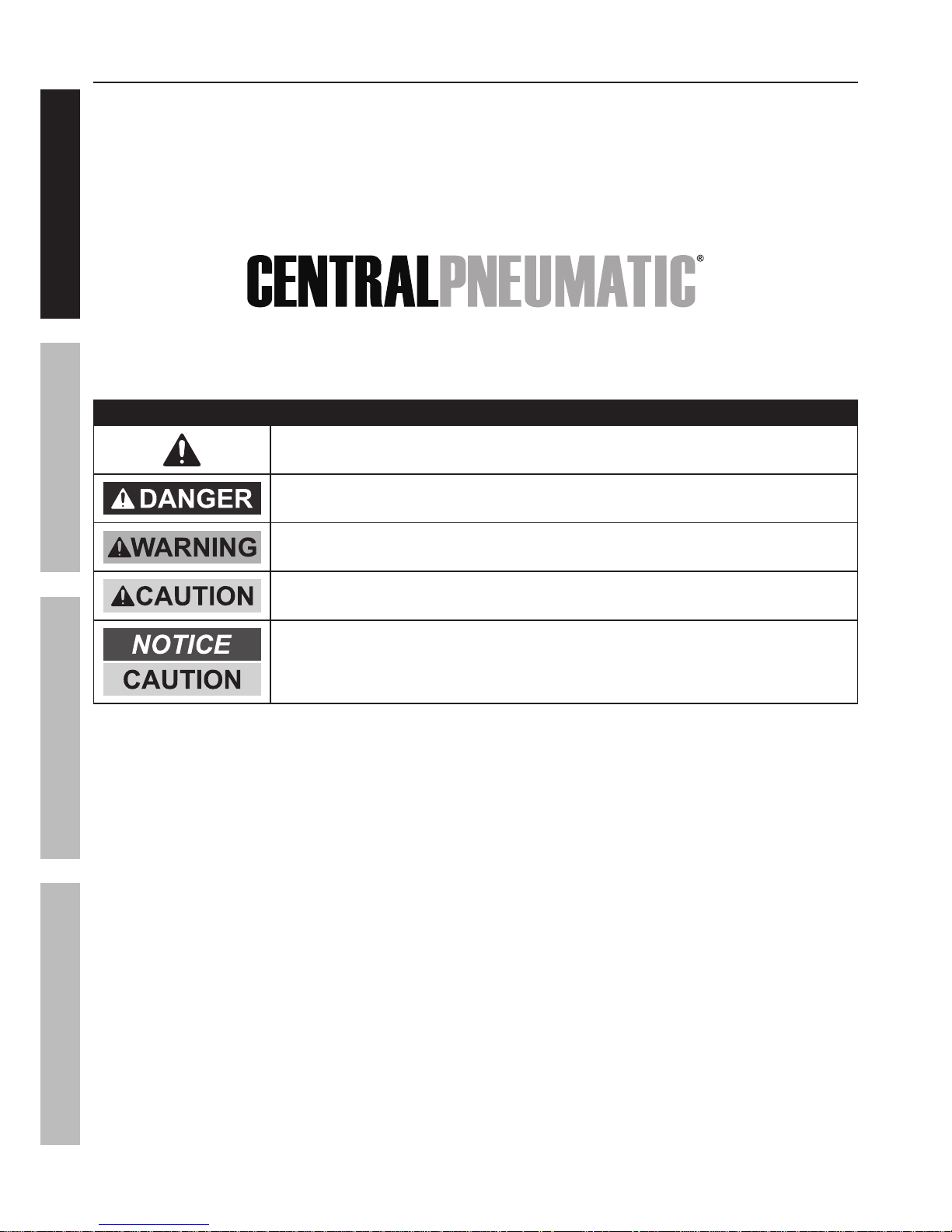
WARNING SYMBOLS AND DEFINITIONS
This is the safety alert symbol. It is used to alert you to potential personal injury hazards.
Obey all safety messages that follow this symbol to avoid possible injury or death.
Indicates a hazardous situation which, if not avoided,
will result in death or serious injury.
Indicates a hazardous situation which, if not avoided,
could result in death or serious injury.
Indicates a hazardous situation which, if not avoided,
could result in minor or moderate injury.
Addresses practices not related to personal injury.

Page 3For technical questions, please call 1-888-866-5797.Item 69269
SAFETYOPERATIONMAINTENANCE SETUP
IMPORTANT SAFETY INFORMATION
General Safety Warnings
WARNING Read all safety warnings and instructions.
Failure to follow the warnings and instructions may result in electric shock, fire and/or serious injury.
Save all warnings and instructions for future reference.
The warnings, precautions, and instructions discussed in this instruction manual cannot cover all possible
conditions and situations that may occur. It must be understood by the operator that common sense
and caution are factors which cannot be built into this product, but must be supplied by the operator.
1. Work area safety
a. Keep work area clean and well lit.
Cluttered or dark areas invite accidents.
b. Do not operate the Compressor in explosive
atmospheres, such as in the presence
of flammable liquids, gases or dust.
Compressor motors produce sparks
which may ignite the dust or fumes.
c. Keep children and bystanders away
from an operating compressor.
2. Electrical safety
a. Compressor plugs must match the outlet.
Never modify the plug in any way.
Do not use any adapter plugs with grounded
compressors. Standard plugs and matching
outlets will reduce risk of electric shock.
b. Do not expose compressor to rain or wet
conditions. Water entering a compressor
will increase the risk of electric shock.
c. Do not abuse the cord. Never use the
cord for unplugging the compressor.
Keep cord away from heat, oil, sharp edges
or moving parts. Damaged or entangled
cords increase the risk of electric shock.
3. Personal safety
a. Stay alert, watch what you are doing and
use common sense when operating this
compressor. Do not use this compressor
while you are tired or under the influence
of drugs, alcohol or medication. A moment
of inattention while operating a compressor
may result in serious personal injury.
b. Use personal protective equipment.
Always wear ANSI-approved eye
protection during setup and use.
c. Prevent unintentional starting. Ensure the
switch is in the off-position before connecting
to power source or moving the compressor.
4. Compressor use and care
a. Do not use the compressor if the switch
does not turn it on and off. Any compressor
that cannot be controlled with the switch
is dangerous and must be repaired.
b. Disconnect the plug from the power source
before making any adjustments, changing
accessories, or storing the compressor.
Such preventive safety measures reduce the
risk of starting the compressor accidentally.
c. Store an idle compressor out of the reach
of children and do not allow persons
unfamiliar with the compressor or these
instructions to operate it. A compressor is
dangerous in the hands of untrained users.
d. Maintain the compressor. Keep the
compressor clean for better and safer
performance. Follow instructions for
lubricating and changing accessories.
Keep dry, clean and free from oil and grease.
Check for misalignment or binding of moving
parts, breakage of parts and any other
condition that may affect the compressor’s
operation. If damaged, have the compressor
repaired before use. Many accidents are
caused by a poorly maintained compressor.
e. Use the compressor in accordance with
these instructions, taking into account
the working conditions and the work to
be performed. Use of the compressor for
operations different from those intended
could result in a hazardous situation.
5. Service
a. Have your compressor serviced by a
qualified repair person using only identical
replacement parts. This will ensure that the
safety of the compressor is maintained.
Page 4 For technical questions, please call 1-888-866-5797. Item 69269
SAFETY OPERATION MAINTENANCESETUP
Air Compressor Safety Warnings
1. Risk of fire or explosion - do not spray flammable
liquid in a confined area or towards a hot surface.
Spray area must be well-ventilated. Do not
smoke while spraying or spray where spark or
flame is present. Arcing parts - keep compressor
at least 20 feet away from explosive vapors,
such as when spraying with a spray gun.
2. Risk of bursting - do not adjust regulator higher
than marked maximum pressure of attachment.
3. Risk of injury - do not direct air
stream at people or animals.
4. Do not use to supply breathing air.
5. Do not leave compressor unattended
for an extended period while plugged in.
Unplug compressor after working.
6. Keep compressor well-ventilated.
Do not cover compressor during use.
7. Drain Tank daily and after use. Internal rust causes
tank failure and explosion.
8. Do not remove the valve cover or
adjust internal components.
9. Compressor head gets hot during operation.
Do not touch it or allow children nearby during
or immediately following operation.
10. Do not use the air hose to move the compressor.
11. Release the pressure in the
storage tank before moving.
12. The use of accessories or attachments not
recommended by the manufacturer may
result in a risk of injury to persons.
13. All air line components, including hoses, pipe,
connectors, filters, etc., must be rated for a minimum
working pressure of 150 PSI, or 150% of the
maximum system pressure, whichever is greater.
14. USE OF AN EXTENSION CORD IS NOT
RECOMMENDED. If you choose to use an
extension cord, use the following guidelines:
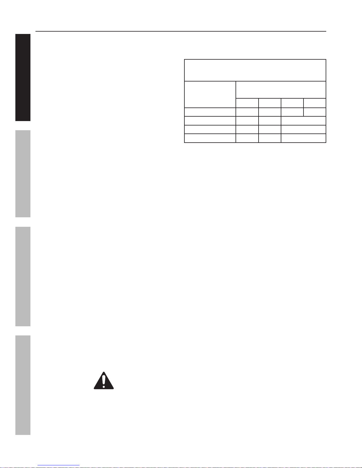
TABLE A: RECOMMENDED MINIMUM WIRE
GAUGE FOR EXTENSION CORDS
(120 VOLT)
NAMEPLATE
AMPERES
(at full load)
EXTENSION CORD
LENGTH
25′ 50′ 100′ 150′
0 – 6 18 16 16 14
6.1 – 10 18 16 Do not use.
10.1 – 12 16 16 Do not use.
12.1 – 16 14 12 Do not use.
a. Make sure your extension cord
is in good condition.
b. Be sure to use an extension cord which is heavy
enough to carry the current your product will draw.
An undersized cord will cause a drop in line
voltage resulting in loss of power and overheating.
Table A shows the correct size to use depending
on cord length and nameplate ampere rating.
If in doubt, use the next heavier gauge. The
smaller the gauge number, the heavier the cord.
15. Industrial applications must follow OSHA guidelines.
16. Maintain labels and nameplates on the
compressor. These carry important safety
information. If unreadable or missing, contact
Harbor Freight Tools for a replacement.
17. This product is not a toy.
Keep it out of reach of children.
18. Operate unit on level surface. Check oil level
daily and fill to marked level if needed.
19. People with pacemakers should consult their
physician(s) before use. Electromagnetic fields in
close proximity to heart pacemaker could cause
pacemaker interference or pacemaker failure.
20. WARNING: The brass components of
this product contain lead, a chemical
known to the State of California to cause
birth defects (or other reproductive harm).
(California Health & Safety code § 25249.5, et seq.)
SAVE THESE INSTRUCTIONS.
Page 5For technical questions, please call 1-888-866-5797.Item 69269
SAFETYOPERATIONMAINTENANCE SETUP
Grounding
TO PREVENT ELECTRIC SHOCK AND DEATH
FROM INCORRECT GROUNDING WIRE CONNECTION:
Check with a qualified electrician if you are in doubt as to whether the outlet is properly grounded.
Do not modify the power cord plug provided with the compressor.
Never remove the grounding prong from the plug. Do not use the compressor if the power cord or plug is
damaged. If damaged, have it repaired by a service facility before use. If the plug will not fit the outlet, have a
proper outlet installed by a qualified electrician.
110-120 VAC Grounded Compressors:
Compressors with Three Prong Plugs
1. In the event of a malfunction or breakdown,
grounding provides a path of least resistance for
electric current to reduce the risk of electric shock.
This compressor is equipped with an electric
cord having an equipment-grounding conductor
and a grounding plug. The plug must be
plugged into a matching outlet that is properly
installed and grounded in accordance
with all local codes and ordinances.
2. Do not modify the plug provided –
if it will not fit the outlet, have the proper
outlet installed by a qualified electrician.
3. Improper connection of the equipment-grounding
conductor can result in a risk of electric shock.
The conductor with insulation having an outer
surface that is green with or without yellow
stripes is the equipment-grounding conductor.
If repair or replacement of the electric cord or
plug is necessary, do not connect the equipmentgrounding conductor to a live terminal.
4. Check with a qualified electrician or service
personnel if the grounding instructions are
not completely understood, or if in doubt as to
whether the compressor is properly grounded.
5. Use only 3-wire extension cords that have
3-prong grounding plugs and 3-pole receptacles
that accept the compressor’s plug.
6. Repair or replace damaged or worn cord immediately.
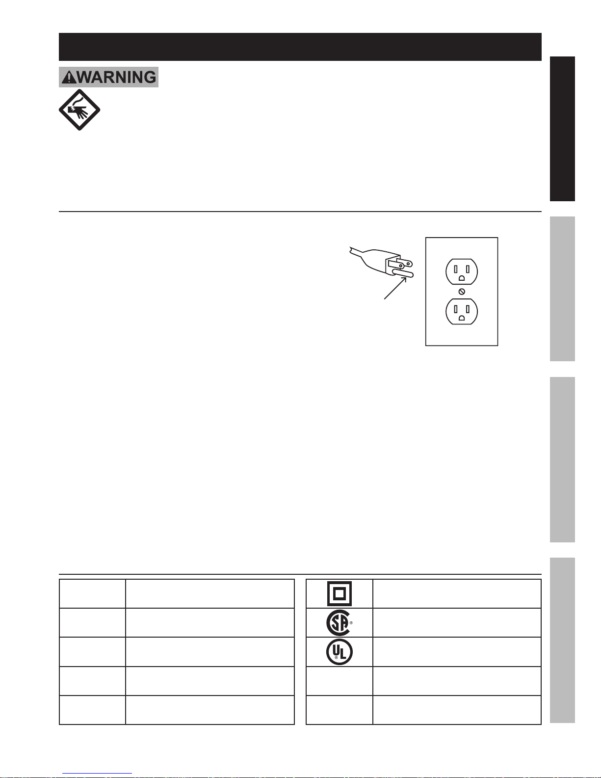
125 VAC 3-Prong Plug and Outlet
(for up to 125 VAC and up to 15 A)
Grounding
Pin
7. This compressor is intended for use on a
circuit that has an outlet that looks like the one
illustrated above in 125 VAC 3-Prong Plug
and Outlet. The compressor has a grounding
plug that looks like the plug illustrated above
in 125 VAC 3-Prong Plug and Outlet.
8. The outlet must be properly installed and grounded
in accordance with all codes and ordinances.
9. Do not use an adapter to connect this
compressor to a different outlet.
Symbology
PSI
Pounds per square inch of pressure
CFM
Cubic Feet per Minute flow
SCFM
Cubic Feet per Minute flow
at standard conditions
NPT
National pipe thread, tapered
NPS
National pipe thread, straight
Double Insulated
Canadian Standards Association
Underwriters Laboratories, Inc.
VAC
Volts Alternating Current
A
Amperes
Page 6 For technical questions, please call 1-888-866-5797. Item 69269
SAFETY OPERATION MAINTENANCESETUP
Specifications
Electrical Rating 120VAC / 60Hz / 2.6A
Air Outlet Size
1
/4″ -18 NPT
Air Pressure
Shut-off 100 PSI
Restart 85 PSI
Air Tank Capacity 3 Gallons
Air Flow Capacity
0.6 CFM @ 90 PSI
1.0 CFM @ 40 PSI
Sound Level 88 dB @ 1m
227847
Instructions for putting into use
Read the ENTIRE IMPORTANT SAFETY INFORMATION section at the beginning of this
manual including all text under subheadings therein before set up or use of this product.
TO PREVENT SERIOUS INJURY FROM ACCIDENTAL OPERATION:
Turn the Power Switch “OFF” and unplug the Air Compressor from its electrical
outlet before assembling or making any adjustments to the compressor.
Note: For additional information regarding the parts listed in the following pages,
refer to the Assembly Diagram near the end of this manual.
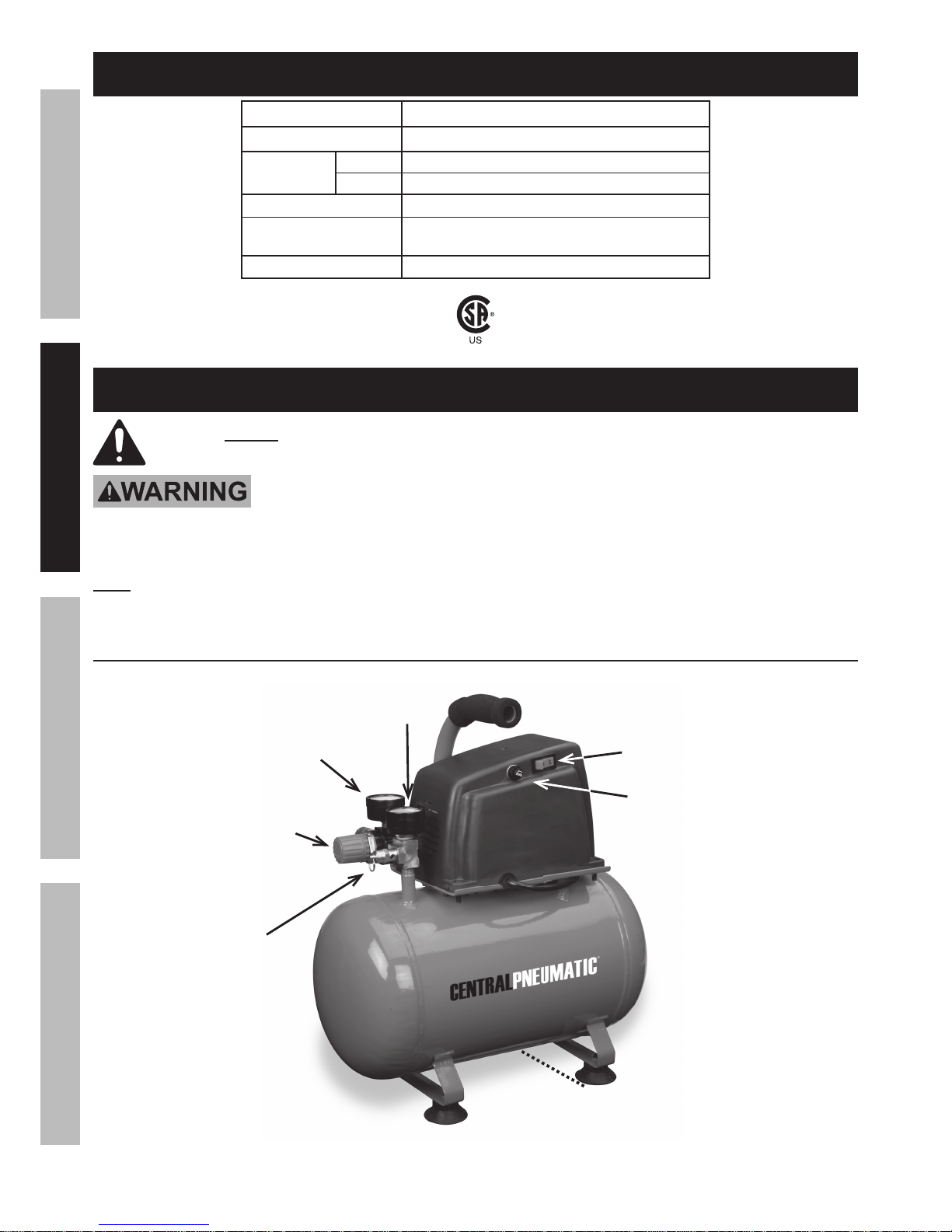
Functions
Figure A
Outlet Pressure
Gauge (70)
Tank Pressure
Gauge (26)
Safety Valve (25)
Pressure Regulator (24)
Drain Valve (54)
ON/OFF Power Switch (45)
Fuse

Page 7For technical questions, please call 1-888-866-5797.Item 69269
SAFETYOPERATIONMAINTENANCE SETUP
Assembly/Mounting
1. Align the two mounting holes in the Handle
with the two threaded mounting holes in the
Bracket on the Air Tank. Secure the Handle
to the Air Tank using the two Screws.
2. Break in the new Air Compressor as follows:
a. Turn the Power Switch off and unplug the unit.
Insert a male coupler (sold separately)
into the female Quick Coupler and fully
open all regulators and valves.
b. Plug in the Power Cord.
c. Turn the Power Switch ON.
d. Let the unit run for 30 minutes.
Air will expel freely through the Coupler.
e. Turn the Power Switch OFF.
f. Unplug the Power Cord and
remove the male coupler.
3. Connect a regulator valve, an inline shut off valve
and a 1/4″ NPT air hose to the Quick Coupler
(all sold separately). The air hose must be long
enough to reach the work area with enough extra
length to allow free movement while working.
Note: An in-line shutoff ball valve is an important
safety device because it controls the air supply even
if the air hose is ruptured. The shutoff valve should
be a ball valve because it can be closed quickly.
4. Depending on the tool which you will be
using with this compressor, you may need to
incorporate additional components, such as an
in-line oiler, a filter, or a dryer (all sold separately),
as shown on Figure B on page 8 and
Figure C on page 9. Consult your air
tool’s manual for needed accessories.
Page 8 For technical questions, please call 1-888-866-5797. Item 69269
SAFETY OPERATION MAINTENANCESETUP
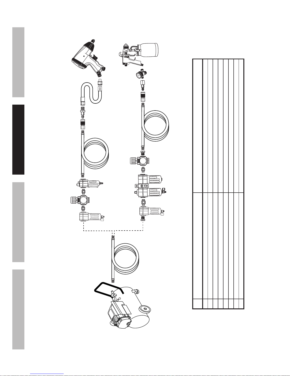
Figure B: Portable Air Supply Setup
G
A
E
E H
F
B
Non-lubricated
Tools
Lubricated
Tools
A
B
C
C
D
A
Description Function
A Air Hose Connects air to tool
B Filter Prevents dirt and condensation from damaging tool or work piece
C Regulator Adjusts air pressure to tool
D Lubricator (optional) For air tool lubrication
E Coupler and Plug Provides quick connection and release
F Leader Hose (optional) Increases coupler life
G Air Cleaner / Dryer (optional) Prevents water vapor from damaging work piece
H Air Adjusting Valve (optional) For fine tuning airflow at tool
Page 9For technical questions, please call 1-888-866-5797.Item 69269
SAFETYOPERATIONMAINTENANCE SETUP
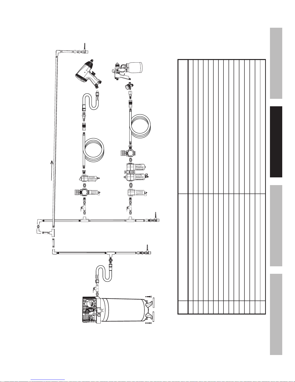
Figure C: Stationary Air Supply Setup
N
L
L O
M
C
C
Non-lubricated
Tools
Lubricated
Tools
H
I
I
J
J
K
H
F
G
E
S lop e
F
F
B B
A
C
D
Description Function
A Vibration Pads For noise and vibration reduction
B Anchor Bolts Secures air compressor in place
C Ball Valve Isolates sections of system for maintenance
D Isolation Hose For vibration reduction
E Main Air Line - 3/4″ minimum recommended Distributes air to branch lines
F Ball Valve To drain moisture from system
G Branch Air Line -1/2″ minimum recommended Brings air to point of use
H Air Hose Connects air to tool
I Filter Prevents dirt and condensation from damaging tool or work piece
J Regulator Adjusts air pressure to tool
K Lubricator (optional) For air tool lubrication
L Coupler and Plug Provides quick connection and release
M Leader Hose (optional) Increases coupler life
N Air Cleaner / Dryer (optional) Prevents water vapor from damaging work piece
O Air Adjusting Valve (optional) For fine tuning airflow at tool

Page 10 For technical questions, please call 1-888-866-5797. Item 69269
SAFETY OPERATION MAINTENANCESETUP
Operating Instructions
Read the ENTIRE IMPORTANT SAFETY INFORMATION section at the beginning of this
manual including all text under subheadings therein before set up or use of this product.
Compressor Area Set Up
1. Designate a work area that is clean and well-lit.
The work area must not allow access by
children or pets to prevent injury.
2. Locate the Compressor on a flat level surface to
ensure proper pump lubrication and to prevent
damage to the unit. Keep at least 12″ of space
around the unit to allow air circulation.
3. Route the power cord from the compressor
to the grounded wall outlet, along a safe path
without creating a tripping hazard or exposing
the power cord to possible damage.
General Operation
1. Close the Drain Valve.
2. Close the in-line Shutoff Valve between
the compressor and the air hose.
3. Plug the Air Compressor Power Cord into
a grounded 120 VAC electrical outlet.
4. Turn the Power Switch ON.
5. Allow the Air Compressor to build
up pressure until it cycles off.
Note: At the beginning of the day’s first use of the
Air Compressor, check for air leaks by applying soapy
water to connections while the Air Compressor is
pumping and after pressure cut-out. Look for air bubbles.
If air bubbles are present at connections, tighten
connections. Do not use the Air Compressor
unless all connections are air tight, the extra air
leaking out will cause the compressor to operate
too often, increasing wear on the compressor.
Note: As long as the Power Switch is ON, the operation
of the Air Compressor is automatic, controlled by an
internal pressure switch. The Compressor will turn on
automatically when the air pressure drops to 85 PSI,
and will turn off automatically when the
air pressure reaches 100 PSI.
WARNING! TO PREVENT SERIOUS
INJURY AND DEATH FROM EXPLOSION:
Do not adjust the internal
pressure switch. Any change to the
automatic pressure levels may cause
excess pressure to accumulate,
causing a hazardous situation.
6. Adjust the Air Compressor’s Pressure Regulator
so that the air output is enough to properly
power the tool, but the output will not exceed
the tool’s maximum air pressure at any time.
Turn the knob clockwise to increase the pressure
and counter-clockwise to decrease pressure.
Adjust the pressure gradually, while checking
the air output gauge to set the pressure.
7. Make sure the air tool’s throttle or switch is in the
off position. Connect the air tool to the air hose.
8. Open the in-line Shutoff Valve.
9. Use the air tool as needed.
10. After the job is complete, turn the Power Switch OFF.
11. Unplug the Air Compressor.
12. Close the in-line Shutoff Valve.
13. Bleed air from the tool then disconnect the tool.
14. Turn the Drain Valve, at the bottom of the Tank,
two turns to release any built-up moisture and the
internal tank pressure. Close the valve after moisture
has drained out. Do not remove the Drain Valve.
15. Clean, then store the Air Compressor indoors.
 Loading...