

Page 1
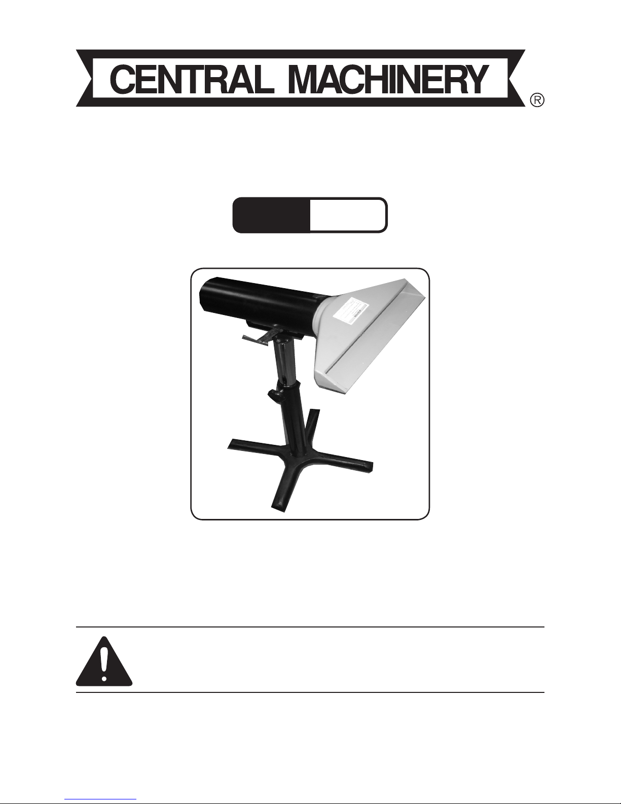
VACUUM, DUST COLLECTOR
WITH STAND
Model
98117
SET UP AND OPERATING INSTRUCTIONS
Diagrams within this manual may not be drawn proportionally.
Due to continuing improvements, actual product may differ slightly from the product described herein.
Distributed exclusively by Harbor Freight Tools®.
3491 Mission Oaks Blvd., Camarillo, CA 93011
Visit our website at: http://www.harborfreight.com
Read this material before using this product.
Failure to do so can result in serious injury.
SAVE THIS MANUAL.
Copyright© 2008 by Harbor Freight Tools®. All rights reserved. No portion of
this manual or any artwork contained herein may be reproduced in any shape
or form without the express written consent of Harbor Freight Tools.
For technical questions or replacement parts, please call 1-800-444-3353.
Page 2
Page 2SKU 98117 For technical questions, please call 1-800-444-3353.
SPECIFICATIONS
Construction
Vacuum Head: Cast
Aluminum
Hose Adaptor: Steel
Tube
Stand Base: Cast
Iron
Vertical Post and
Adjustable Insert:
Steel Tubing
Hose Adapter
Dimensions
3-13/16” I.D. X 4”
O.D.
Height
Adjustment
Lowest: 27-1/2”
Highest: 47-1/4”
Vacuum Head
Rotation Range
360° Without Hose
Vacuum Head
Angle
180° Adjustment
UNPACKING
When unpacking, check to make
sure that the item is intact and undamaged. If any parts are missing or broken,
please call Harbor Freight Tools at the
number shown on the cover of this manual
as soon as possible.
SAFETY INFORMATION
Read the ENTIRE
IMPORTANT SAFETY
INFORMATION section at the
beginning of this manual
including all text under
subheadings therein before set
up or use of this product.
To prevent injury:
Keep Dust Collector Head clear of 1.
moving parts.
Secure all adjustments before use.2.
Wear ANSI-approved safety 3.
goggles and dust mask/respirator
during setup and use.
Use on at, level and hard surface 4.
only.
Inspect before using; do not use if 5.
parts are loose, or damaged.
Follow all manufacturer’s instruc-6.
tions and safety warnings for
tool(s) used with this Dust Collector.
Assembly Safety Precautions
Assemble only according to these 1.
instructions. Improper assembly can
create hazards.
Wear ANSI-approved safety goggles 2.
and heavy-duty work gloves during
assembly.
Keep assembly area clean and well 3.
lit.
Do not assemble when tired or when 4.
under the inuence of drugs or medi-
cation.
This product is not a toy. Do not allow 5.
children to play with or near this item.
Follow all manufacturer’s safety warn-6.
ings, and specic instructions for each
different tool used with this Vacuum,
Dust Collector.
Use for intended purpose(s) only.7.
Inspect before use; do not use if parts 8.
are loose or damaged.
Maintain product labels and name-9.
plates. These carry important safety
information. If unreadable or missing,
contact Harbor Freight Tools for a
replacement.
Page 3

Page 3SKU 98117 For technical questions, please call 1-800-444-3353.
ASSEMBLY INSTRUCTIONS
Attach one Rubber Foot Pad (7) to 1.
bottom of each support leg on Base
(1).
Place Base (1) on at, level surface 2.
and attach Vertical Tube (2) to Base
(1) using Hex-Head Screw (10) and
Flat Washer (13) and securely tighten
to prevent wobble when attaching
other parts.
Slide the Adjustable Tube (4) into the 3.
Vertical Tube (2). Leave approximately three inches of the Adjustable
Tube (4) sticking out of the Vertical
Tube (2). Secure the Adjustable Tube
(4) in place using the Knob (8).
Thread the Bracket Tube Holder (15) 4.
into the top of the Adjustable Tube
(4), using 2 recessed Head Screws
(12). Tighten securely but do not over
tighten.
Attach The Vacuum Tube (14) to the 5.
Bracket Tube Holder (15) using the
Attachment Bolt (5) and Sliding Bar
(6) to tighten. Do not over tighten.
Slide the Dust Collector Head (11) 6.
into the Vacuum Tube (14). Tighten
the Lock Knob (16) to hold the Dust
Collector Head (11) in place.
Recheck all Nuts, Handles and Knobs 7.
for security before using.
OPERATION INSTRUCTIONS
Adjust height of Dust Collector Head 1.
(11) by raising or lowering the Adjustable Tube (4). Loosen the Knob (8) to
raise or lower. Tighten the Knob (8)
to hold the Adjustable Tube (4) at the
selected height.
Adjust the Angle of the Vacuum Tube 2.
(14) by loosening the Attachment Bolt
(5). Set the needed angle and use
the Attachment Bolt (5) to retighten.
Adjust the Angle of the Dust Col-3.
lector Head (11) by loosening the
Lock Knob (16), setting the needed
angle and retightening the Lock Knob
(16). NOTE: The Lock Knob (16)
will thread into an existing hole if
needed to secure the Dust Collector Head in the Horizontal Position.
If another angle is needed, thread
the Lock Knob against the neck
of the Dust Collector Head tight
enough to prevent movement.
Position the Dust Collector Head (11) 4.
as close to the area where most of the
dust from your project will accumulate being careful to stay clear of all
belts, disks, and other moving parts
associated with the cutting, sanding
or grinding tool you are using. This
includes leaving space to use your
hands without coming in contact with
the Dust Collector Head (11).
Follow all manufacturer’s instructions 5.
and safety warnings when using any
tool with this Vacuum Dust Collector.
Never place the Dust Collector Head
close to moving parts.
This Vacuum Dust Collector has a 6.
4” Vacuum Tube (14). In order to
connect a dust collecting system with
other than a 4” attachment, you must
have a 4” to 3” or 2” adapter. NOTE:
Using a smaller hose and duct tape to
prevent air leakage is not acceptable,
or safe.
Always re-check all knobs, bolts and 7.
nuts for security before using this tool.
Page 4

Page 4SKU 98117 For technical questions, please call 1-800-444-3353.
PARTS LIST
Part # Discription Qty
1 Base 1
2 Vertical Tube 1
3 Fixed Ring Outer Tube 1
4 Adjustable Tube 1
5 Attachment Bolt 1
6 Sliding Bar 1
7 Rubber Foot Pad 4
8 Knob 1
9 Screw Socket 3
10 Hex-Head Screw 1
11 Dust Collector Head 1
12 Screws 2
13 Flat Washer 1
14 Vacuum Tube 1
15 Bracket Tube Holder 1
16 Lock Knob 1
PLEASE READ THE FOLLOWING CAREFULLY
THE MANUFACTURER AND/OR DISTRIBUTOR HAS PROVIDED THE PARTS LIST AND ASSEMBLY DIAGRAM IN THIS MANUAL AS A REFERENCE TOOL ONLY. NEITHER THE MANUFACTURER OR DISTRIBUTOR MAKES ANY REPRESENTATION OR WARRANTY OF ANY
KIND TO THE BUYER THAT HE OR SHE IS QUALIFIED TO MAKE ANY REPAIRS TO THE
PRODUCT, OR THAT HE OR SHE IS QUALIFIED TO REPLACE ANY PARTS OF THE PRODUCT. IN FACT, THE MANUFACTURER AND/OR DISTRIBUTOR EXPRESSLY STATES THAT
ALL REPAIRS AND PARTS REPLACEMENTS SHOULD BE UNDERTAKEN BY CERTIFIED
AND LICENSED TECHNICIANS, AND NOT BY THE BUYER. THE BUYER ASSUMES ALL RISK
AND LIABILITY ARISING OUT OF HIS OR HER REPAIRS TO THE ORIGINAL PRODUCT OR
REPLACEMENT PARTS THERETO, OR ARISING OUT OF HIS OR HER INSTALLATION OF
REPLACEMENT PARTS THERETO.
Page 5

Page 5SKU 98117 For technical questions, please call 1-800-444-3353.
ASSEMBLY DIAGRAM
Record Product’s Serial Number Here:
Note: If product has no serial number, record month and year of purchase instead.
Note: Some parts are listed and shown for illustration purposes only, and are not
available individually as replacement parts.
 Loading...