

Page 1
WATER PUMP
®
Model 93121 / 94074 / 94075
ASSEMBLY AND OPERATING INSTRUCTIONS
3491 Mission Oaks Blvd., Camarillo, CA 93011
Visit our Web site at: http://www.harborfreight.com
TO PREVENT SERIOUS INJURY,
READ AND UNDERSTAND ALL WARNINGS
AND INSTRUCTIONS BEFORE USE.
Copyright© 2005 by Harbor Freight Tools®. All rights reserved. No portion of this
manual or any artwork contained herein may be reproduced in any shape or form
without the express written consent of Harbor Freight Tools.
For technical questions, please call 1-800-444-3353.
Page 2
PRODUCT SPECIFICATIONS
ledoM470495704912139
etaRwolFmumixaMMPG731MPG462MPG801
eziSpmuP retemaiDhcnI8
epyTpmuP lagufretneC
deepSpmuPMPR000
,4
gnimirP-fleSoN
noitcuSdaeHmumixaM'72
tfiLdaeHlatoT'401'461
epyTenignE
3
/
epyT/yticapaCleuF
4
,delooCriA,PH5.4
tratSlioceR,ekortS-4
dedaelnU/.laG
enilosaG
,
delooCriA,PH6
tratSlioceR,ekortS-4
enilosaGdedaelnU/.laG1
yticapaCliOenignE.tQ36.
thgieWlatoT.sbL1.55.sbL8.56.sbL06
seiros
seccA
)1.ytQ(tekcoSgulPkrapS
,)2.ytQ(sgnilpuoCesoH,)3.ytQ(spmalCesoH,)1.ytQ(reniartS
NOTE: This product requires oil and fuel to be added before starting.
Attempting to start the engine without oil WILL ruin the engine and void
the warranty.
Before starting the engine, refer to the engine owner’s manual for
engine maintenance information.
12139
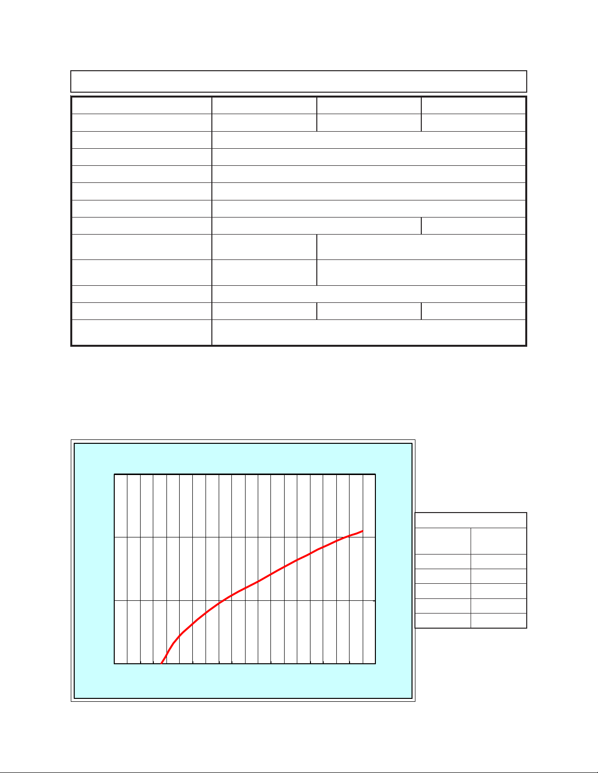
yticapaC
)MPG(
(gal/min)
0246
erusserP
)ISP(
0445
0664
0802
0018
93121 Performance Chart
0 50 100 150
0
10
20
30
40
50
60
70
80
90
100
110
120
130
140
150
160
170
180
190
200
SKU 93121/94074/94075 For technical questions, please call 1-800-444-3353. PAGE 2
(ft.)
REV 08/05
Page 3
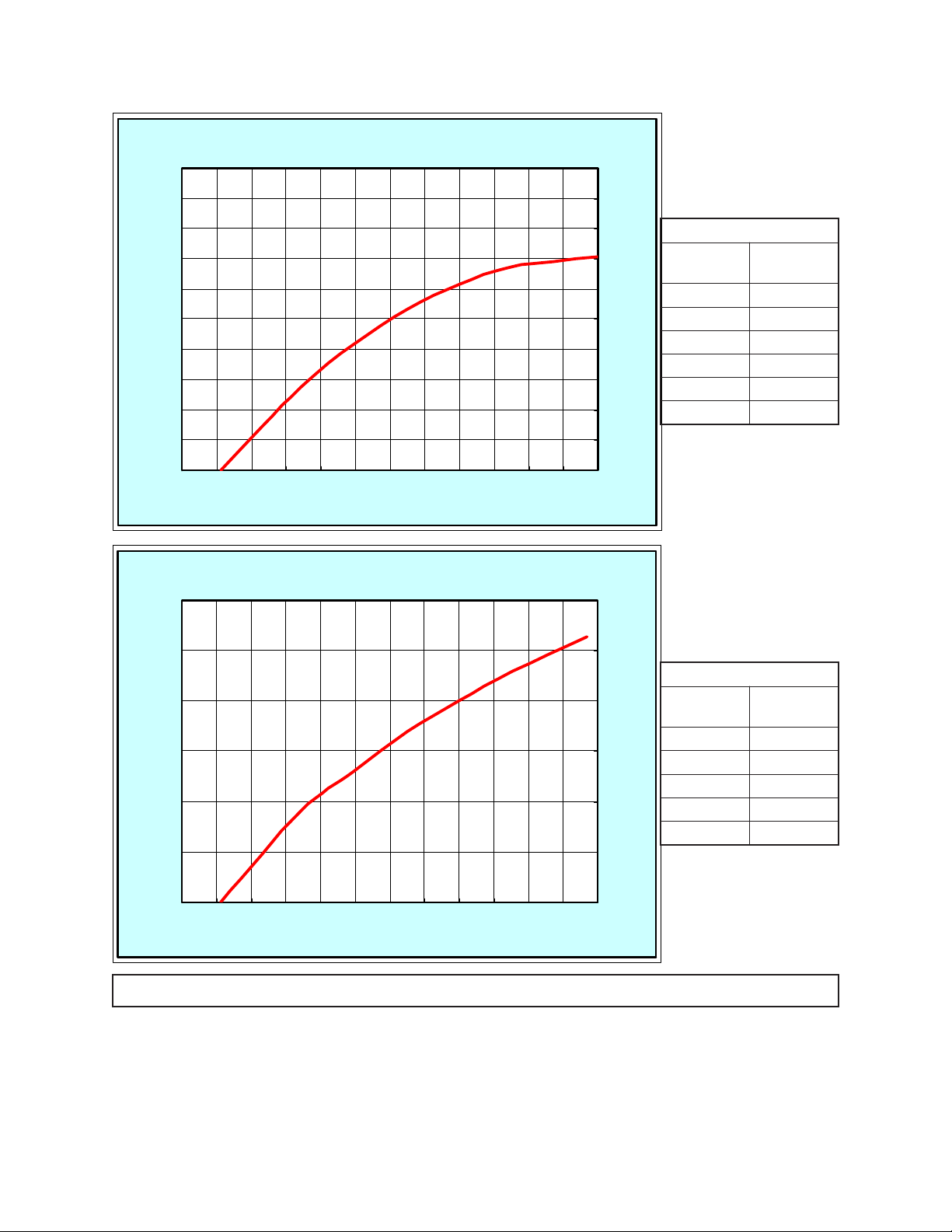
47049
yticapaC
)MPG(
erusserP
)ISP(
0284
(gal/min)
0404
0663
0813
00162
02191
94074 Performance Chart
0 20 40 60 80 100 120 140 160 180 200
0
10
20
30
40
50
60
70
80
90
100
110
120
(ft.)
57049
yticapaC
)MPG(
(gal/min)
0524
erusserP
)ISP(
00173
05182
00271
0528
94075 Performance Chart
0 50 100 150 200 250 300
0
10
20
30
40
50
60
70
80
90
100
110
120
(ft.)
SA VE THIS MANU AL
You will need this manual for the safety warnings and precautions, assembly, operating,
inspection, maintenance and cleaning procedures, parts list and assembly diagram.
Keep your invoice with this manual. Write the invoice number on the inside of the front
cover. Keep this manual and invoice in a safe and dry place for future reference.
REV 08/05
SKU 93121/94074/94075 For technical questions, please call 1-800-444-3353. PAGE 3
Page 4

GENERAL SAFETY RULES
IMPORTANT SAFETY INSTRUCTIONS
WARNING!
READ AND UNDERSTAND ALL INSTRUCTIONS
Failure to follow all instructions listed below may result in
electric shock, fire, and/or serious injury.
SA VE THESE INSTRUCTIONS
WORK AREA
1. Keep your work area clean and well lit. Cluttered and dark work areas
invite accidents.
2. Do not operate the Water Pump in explosive atmospheres, such as in the
presence of flammable liquids, gases, or dust. Power equipment creates
sparks which may ignite the dust or fumes.
3. Keep bystanders, children, and visitors away while operating the W ater
Pump. Distractions can cause you to lose control.
PERSONAL SAFETY
4. Stay alert. Watch what you are doing, and use common sense when
operating a water pump. Do not use a water pump while tired or under the
influence of drugs, alcohol, or medication. A moment of inattention while
operating water pumps may result in serious personal injury.
5. Dress properly. Do not wear loose clothing or jewelry. Contain long hair.
Keep your hair, clothing, and glo ves away from mo ving parts. Loose clothes,
jewelry, or long hair can be caught in moving parts.
6. Do not overreach. Keep proper footing and balance at all times. Proper
footing and balance enables better control of the Water Pump in unexpected
situations.
7. Always wear eye protection. W ear ANSI appro ved safety impact
goggles and nonskid rubber boots. A hardhat must be used for
appropriate conditions.
TOOL USE AND CARE
8. Do not force the Water Pump. Use the correct Water Pump for your
application. The correct Water Pump will do the job better and safer at the rate
for which it is designed.
SKU 93121/94074/94075 For technical questions, please call 1-800-444-3353. PAGE 4
Page 5

9. Do not use the Water Pump if the Power Switch on the Engine does not
turn iton or off. Any Water Pump equipment that cannot be controlled is
dangerous and must be repaired or replaced.
10. Store idle tools and equipment out of reach of children and other untrained
persons. Tools and equipment are dangerous in the hands of untrained users.
11. Maintain the Water Pump with care. Keep the Water Pump clean. A properly
maintained Water Pump is easier to control. Do not use damaged tools and
equipment. Tag damaged tools and equipment “Do not use” until repaired.
12. Check for misalignment or binding of mo ving parts, broken parts, and any
other condition that may affect the Water Pump’s operation. If damaged,
have the Water Pump serviced before using. Many accidents are caused by
poorly maintained tools and equipment.
13. Use only accessories that are recommended by the manufacturer f or your
model. Accessories that may be suitable for one Water Pump may become
hazardous when used on another Water Pump.
SERVICE
14. Water Pump service must be performed only by qualified repair personnel.
Service or maintenance performed by unqualified personnel could result in a risk
of injury.
15. When servicing the Water Pump, use only identical replacement parts.
Follow instructions in the
of this manual. Use of unauthorized parts or failure to follow maintenance
instructions may create a risk of electric shock or injury.
“Inspection, Maintenance, And Cleaning”
section
SPECIFIC SAFETY RULES
General Precautions
1. WARNING! The w arnings, precautions , and instructions discussed in this
manual cannot cover all possible conditions and situations that may occur. The
operator must understand that common sense and caution are factors, which
cannot be built into this product, but must be supplied by the operator.
2. WARNING! People with pacemakers should consult their physician(s)
before using this product. Electromagnetic fields in close proximity to a heart
pacemaker could cause interference or failure of the pacemaker. In addition,
people with pacemakers should adhere to the following: Caution is necessary
when near the magneto and spark plug of a running engine.
3. Industrial applications must follow OSHA requirements.
4. Maintain labels and nameplates on the Water Pump. These carry important
information. If unreadable or missing, contact Harbor Freight Tools for a
replacement.
SKU 93121/94074/94075 For technical questions, please call 1-800-444-3353. PAGE 5
Page 6

Installation Precautions:
1. WARNING! Before using the Water Pump, read and understand the
manufacturer’s
precautions in
Operation, Maintenance, and Parts manual.
this
manual. These should always be followed to reduce the risk of
Also, read the safety
Engine
personal injury and damage to equipment.
2. Use the Water Pump only in well ventilated outdoor areas. Carbon
monoxide is produced during operation, and is a colorless, odorless gas
that, if inhaled, can cause SERIOUS INJURY or DEATH.
3. When using the Water Pump outdoors, it must be weatherproofed and should be
soundproofed.
4. Never lift this equipment using the engine or water pump. Connect lifting
equipment to the Frame of the equipment.
5. Before lifting the Water Pump, ensure the lift rigging and supporting structure are
in good condition, and are rated to lift such a load.
6. Keep all personnel away from the suspended Water Pump during relocating.
7. The supporting floor/ground surface should be level, and strong enough to safely
hold the weight of the Water Pump. If the floor/ground surface is not level, strong
cross members should be placed under the full length of the Water Pump Frame
at its low side.
8. Make sure the intake and discharge hoses (not included) are secured to a
solid surface to ensure the stability of the Water Pump.
9. For trailer installation, the Water Pump should be mounted on the center point of
the trailer, over the wheels.
Fire And Explosion Precautions:
1. Do not pump hazardous materials. Do not pump explosive or flammable
materials such as fuel oil, kerosene, gasoline, etc. Do not pump in close
proximity to flammable or explosive materials. The Water Pump is designed to
move clean or dirty water only. Do not pump water over 104° Fahrenheit.
2. Gasoline fuel and fumes are flammable, and potentially explosive. Use proper
fuel storage and handling procedures. Always have multiple ABC class fire
extinguishers nearby.
3. Keep the Water Pump and surrounding area clean at all times.
4. When spills of fuel or oil occur, they must be cleaned up immediately. Dispose of
fluids and cleaning materials as per any local, state, or federal codes and
regulations. Store oil rags in a covered metal container.
5. Never store fuel or other flammable materials near the Water Pump.
6. Do not smoke, or allow sparks, flames or other sources of ignition around the
Engine and Fuel Tank. Fuel vapors are explosive.
7. Keep grounded conductive objects, such as tools, away from exposed, live elec-
SKU 93121/94074/94075 For technical questions, please call 1-800-444-3353. PAGE 6
Page 7

trical parts and connections to avoid sparking or arcing. These events could
ignite fumes or vapors.
8. Do not refill the Fuel Tank while the Engine is running or while the Engine is still
hot. Do not operate the Water Pump with known leaks in the fuel system.
9. Excessive buildup of unburned fuel gases in the exhaust system can create a
potentially explosive condition. This buildup can occur after repeated failed start
attempts, valve testing, or hot engine shutdown. If this occurs, open exhaust
system drain plugs, if equipped, and allow the gases to dissipate before
attempting to restart the Engine.
10. Use only engine manufacturer recommended fuel and oil.
Mechanical Precautions:
1. ALWAYS make sure the Engine’ s Power Switch is in its “OFF” position.
Disconnect the spark plug wire, and allow the Engine to completely cool before
carrying out maintenance.
2. Use the right product for the job. There are certain applications for which this
product was designed. Do not use small equipment, tools, or attachments to do
the work of larger industrial equipment, tools, or attachments. Do not use this
product for a purpose for which it was not intended.
3. In cold weather, when the Water Pump is not in use, protect the interior of
the Pump from freezing by draining the liquid and pumping a permanent
type automobile antifreeze containing a rust inhibitor through the system. A
50% mixture with water is recommended. Be sure to flush the system with a
neutralizing liquid prior to reuse of the unit. NOTE: Antifreeze is poisonous and
could cause serious personal injury if ingested. ALWAYS dispose of antifreeze properly.
4. Prior to use, and periodically thereafter, check to make sure all connections
are tight and secure.
5. Check for damaged parts. Before using the Water Pump, any part that appears
damaged should be carefully checked to determine that it will operate properly
and perform its intended function. Check for alignment and binding of moving
parts, any broken parts or mounting fixtures, and any other condition that may
affect proper operation. Any part that is damaged should be properly repaired or
replaced by a qualified technician.
6. The Water Pump is designed with guards for protection from moving parts.
In any case, care must still be taken to protect personnel and equipment from
other mechanical hazards when working around the Water Pump.
7. Do not operate the Water Pump with safety guards removed.
8. The Water Pump must never be run dry. Always make sure to completely fill
the Pump Casing (1) with water prior to operating the unit. Not doing so may
damage the inner seals which depend on the water for lubrication.
SKU 93121/94074/94075 For technical questions, please call 1-800-444-3353. PAGE 7
Page 8

9. Always f ollow and complete scheduled Engine and W ater Pump maintenance.
Chemical Precautions:
1. Avoid contact with hot fuel, oil, exhaust fumes, and solid surfaces.
2. Avoid body contact with fuels, oils, and lubricants used in the Engine. If
swallowed, seek medical treatment immediately. Do not induce vomiting if fuel is
swallowed. For skin contact, immediately wash with soap and water. For eye
contact, immediately flush eyes with clean water.
Noise Precautions:
Prolonged exposure to noise levels above 85 dBA is hazardous to hearing.
Always wear ANSI approved ear protection when operating or working around the
Water Pump when it is running.
UNPACKING
When unpacking, check to mak e sure all the parts shown on the Parts Lists on pages 15
and 16 are included. If any parts are missing or broken, please call Harbor F reight Tools at
the number shown on the cov er of this manual as soon as possible.
GENERAL LOCATION
1. It is recommended to locate and install the Water Pump outdoors where cooling
air is readily available.
2. Install the Water Pump so that the engine air inlets and outlets are not blocked by
obstructions such as bushes, trees, or snow drifts. Locating it in the path of
heavy winds or snowdrifts may require the placement of a barrier f or protection.
The air inlet, in normal weather conditions, should face the pre vailing wind
direction.
3. Install the Water Pump on a concrete slab or other area where rain drainage or
flood waters can not reach it.
4. Water Pump placement should allo w four feet of access to all sides f or maintenance.
5. Place the Water Pump as close as possible to the water that will be pumped to
reduce the length of hoses.
WATER PUMP SUPPORT AND MOUNTING
For permanent or semi-permanent installation: Mount the Water Pump on a
concrete slab capable of supporting the weight of the unit. The slab must extend
on all sides beyond the Frame (33) by at least one foot. Contact a cement contractor for slab specifications if necessary. Attach the Frame to the concrete slab
using 3/8” diameter expansion anchor bolts (not supplied).
SKU 93121/94074/94075 For technical questions, please call 1-800-444-3353. PAGE 8
Page 9

ASSEMBLY INSTRUCTIONS
NOTE: For additional information regarding the parts listed in the following pages, refer
to the Assembly Diagrams on pages 15 and 16.
WARNING! Always turn off the Power Switch to the Engine and remove its
spark plug
any adjustments to the Pump. Once finished, reinstall the spark plug.
To Assemble The Intake Hose And Discharge Hose:
1. NOTE: The sizes of Hose Couplings (18, 28) on the three Water Pump models
discussed in this manual are as follows:
Model 93121 = 2”
Model 94074 = 2”
Model 94075 = 3”
Intake and Discharge Hoses (not included) with a diameter corresponding to
model (93121, 94074, or 94075)
enlarge the discharge size below or above your Water Pump model as this will
affect Pump flow and performance. (See Figure A, next page.)
prior
to assembling the Water Pump, unclogging the Pump, or making
must
be used. Do not attempt to reduce or
your
2. Assemble the
(17), one Hose Coupling (18), two Hose Bands (31), and one Strainer (32).
(See Figure A.)
3. Assemble the
(27), one Hose Coupling (28), and one Hose Band (31). (See Figure A.)
COUPLING
PACKING
(17)
HOSE
COUPLING
(18)
Intake
Hose, using one Hose Joint (16), one Coupling Packing
Discharge
HOSE
JOINT
HOSE
(16)
BAND
(31)
Hose, using one Hose Joint (26), one Coupling Packing
INTAKE HOSE
(NOT INCLUDED)
HOSE
BAND
(31)
DISCHARGE HOSE
(NOT INCLUDED)
(26)
HOSE
BAND
(31)
FIGURE A
HOSE
COUPLING
COUPLING
PACKING
(27)
SKU 93121/94074/94075 For technical questions, please call 1-800-444-3353. PAGE 9
(28)
HOSE
JOINT
Page 10

To Attach The Intake Hose And Discharge Hose To The Water Pump:
1. Intake hose must be designed for suction so that it does not collapse. To
attach the
Intake
Hose to the Water Pump, position the Hose Coupling (18)
against the threaded/intake opening in the Casing (1). Then, firmly screw the
Hose Joint (16) onto the opening. (See Figures A and B.)
2. To attach the
Discharge
Hose to the Water Pump, position the Hose Coupling
(28) against the threaded/discharge opening in the Bend (19). Then, firmly screw
the Hose Joint (26) onto the opening. (See Figures A and B.)
DISCHARGE
OPENING
INTAKE
OPENING
BEND
(19)
CASING
(1)
FIGURE B
3. Route the Discharge Hose as needed to direct the discharge to the desired
location. The Discharge Hose should be kept as short as possible with a
minimum number of turns.
4. Make sure the area where the Strainer (32) on the Intake Hose is located is free
from accumulated debris, rocks, and other objects that may damage the Pump.
OPERATING INSTRUCTIONS
NOTE:
For additional references to the parts discussed in the following pages,
refer to the Assembly Diagrams on pages 15 and 16 of this manual.
Engine Pre-Start Checks:
1. Before operation, it will be necessary to refer to the
Operation, Maintenance, and Parts manual
(included) for detailed information
about starting, running, and stopping the Engine.
2. IMPORTANT! Engine oil MUST be added to the Engine’s crankcase prior to
starting and running the Engine. Failure to add oil, according to the Engine
manufacturer’s recommendations, will damage the Engine and void its warranty.
(See
Engine
SKU 93121/94074/94075 For technical questions, please call 1-800-444-3353. PAGE 10
manufacturer’s manual.)
Engine manufacturer’s
Page 11

3. Check to make sure the Engine’s “ON/OFF” Switch is in its “OFF” position.
(See
Engine
manufacturer’s manual.)
4.
Unscrew
and remove one of the Engine’s Oil Dipsticks located on either side at
the bottom of the Engine Crankcase. Fill the Engine’ s crankcase with the proper
type
and
amount
Then, replace the Oil Dipstick. (See
of engine oil as recommended by the Engine manufacturer.
Engine
manufacturer’s manual.)
5. Before the first use, remove the Engine’s Fuel Tank Cap and fill the Fuel Tank with
unleaded
Tank for the amount of
gasoline. Then, replace the Fuel Tank Cap. Thereafter, check the Fuel
unleaded
gasoline in the Fuel Tank. If necessary, refill the
Fuel Tank with unleaded gasoline.
(See
Engine
manufacturer’ s man ual.)
Water Pump Pre-Start Checks:
1. IMPORTANT ! The Water Pump MUST be primed with water prior to each
use of the unit. The Water Pump must never be run dry. Always make sure to
completely fill the Pump Casing (1) with water prior to operating the unit. Not
doing so may damage the inner seals which depend on the water for lubrication.
To fill the Pump Casing, unscrew and remove the Plug (22) located at the top of
the Bend (19). Fill the Pump Casing completely with water. Then, replace the
Plug. (See Figure C.)
FIGURE C
PLUG
(22)
SKU 93121/94074/94075 For technical questions, please call 1-800-444-3353. PAGE 11
Page 12

OPERATING INSTRUCTIONS
REFER TO ENGINE MANUFACTURER’S DOCUMENTATION FOR DETAILED
ENGINE OPERATION INSTRUCTIONS AND PRECAUTIONS.
To Start The Water Pump:
1. Check the Engine oil level. Before checking the Engine oil level, make sure the
Engine is not running and is placed on a level surf ace.
2. Check the Engine Fuel level in the gasoline Tank. Do not overfill the Tank. Do not
fill the fuel Tank when the Engine is running.
3. Check the Intake and Discharge Hoses for weak or worn conditions before each
use. Check to make sure all connections are tight and secure.
4. Check to make sure the Water Pump is primed.
5. Make sure the Engine and Water Pump turns freely by hand. If it cannot be
turned over by pulling on the recoil starter rope, have a qualified service
technician open the Casing (1) of the Water Pump to remove obstructions lodged
in the unit.
6. Turn on the Engine’s power switch, and start the Engine by pulling the recoil
starter rope out quickly and forcefully. Repeat pulling until the Engine starts.
7. Idle the Engine for 3-5 minutes to allow it to warm up. Then, open the throttle
lever and allow the Engine to run faster.
8. As the Water Pump begins operating, it will cause an increased load upon the
Engine. Open the Engine throttle lever further to increase the Engine speed
adequately for the pumping operation.
To Stop The Water Pump:
1. To stop the Water Pump for a short period of time, run the Engine throttled all the
way down and turn the Engine power switch to its “OFF” position.
2. To stop the Water Pump for a long period of time, turn the Engine fuel lever to its
“OFF” position instead of turning the Engine power switch off. Allow the Engine
to idle for 2-3 minutes until the fuel in the Engine carburetor is depleted and the
Engine stops. Then, turn the Engine power switch to its “OFF” position. Drain all
the Engine fuel from the fuel tank and fuel lines. NOTE: Throughout this
process, check to make sure there is water in the Water Pump’s priming
chamber.
3. After use, if the pump is to remain idle for a period, drain all water from pump and
hoses.
SKU 93121/94074/94075 For technical questions, please call 1-800-444-3353. PAGE 12
Page 13

INSPECTION, MAINTENANCE, AND CLEANING
1. WARNING! Always make sure the Engine’s power switch is turned off and
prior
to performing any inspection, maintenance, or cleaning of the Water Pump.
2. Before each use, inspect the general condition of the Water Pump. Check for
clogs throughout the system, misalignment or binding of moving parts, damaged or
loose intake and discharge hoses, and an y other condition that ma y aff ect the safe
operation of the Water Pump. If abnormal noise or vibration occurs, have the problem corrected before further use. Do not use damaged equipment.
3. Periodically, check to mak e sure the area where the W ater Pump’ s Strainer (32) is
located is free from accumulated debris, rocks, and other objects that ma y damage
the Pump.
4. When cleaning, spray the exterior and Strainer (32) of the Water Pump with a
garden hose. Do not introduce water or an y other liquid into the intake and e xhaust
ports of the Engine.
5. In cold weather, when the Water Pump is not in use, protect the interior of the
Pump from freezing by draining the water and pumping a permanent type automobile
antifreeze containing a rust inhibitor through the system. A 50% mixture with water
is recommended. Be sure to flush the system with a neutralizing liquid prior to
reuse of the unit. NOTE: Antifreeze is poisonous and could cause serious
personal injury if ingested. ALWAYS dispose of anti-freeze properly.
6. T o drain the W ater Pump, unscre w and remove the Plug (22) located at the bottom
of the Casing (1). Replace the Plug and securely tighten. (See Figure D.)
7. W ARNING! All maintenance, service, or repairs not listed in this manual should
only be performed by a qualified service technician.
FIGURE D
PLUG
(22)
SKU 93121/94074/94075 For technical questions, please call 1-800-444-3353. PAGE 13
Page 14

TROUBLESHOOTING
1. Engine does not start.
A. Make sure the Engine’s power switch is in its “ON” position.
B. Make sure the Engine’s fuel lever is open.
C. Make sure the Engine’s throttle lever is open.
D. Make sure the Engine has adequate fuel and oil.
E. Make sure the Engine’s spark plug and spark plug wire are firmly connected.
F. Check the Engine manufacturer’s manual for further instructions.
2. Water Pump runs, but does not discharge water.
A. Make sure the Water Pump has been primed.
B. Discharge hose may be frozen or blocked. Check to see if discharge hose
passes through cold areas or is blocked or kinked.
C. Intake hose may be frozen, b loc ked, damaged, or has a loose connection.
Thoroughly clean the Strainer (32) on the intake hose and check for any loose
connections. Check to see if intake hose passes through cold areas or is
blocked or kinked. Intake hose must be designed for suction so that it does
not collapse.
D. Vertical lift is beyond the Water Pump’s capability. Check the
Specifications”
section (page #2) for your Water Pump model’s maximum lift
“Product
capability. If necessary, reduce height of vertical lift.
E. Impeller of the Water Pump is jammed. Clean the Impeller. If necessary,
have a qualified service technician inspect the Impeller.
3. Pump Motor runs, but delivers small amount of water.
A. Vertical lift is approaching Water Pump’s maximum lift capability. Check the
“Product Specifications”
section (page #2) for your Water Pump model’s
maximum lift capability. If necessary, reduce height of vertical lift.
B. Strainer (32) is partially blocked. Check to make sure Strainer is clear of
debris.
C. Intake and/or discharge hose is partially blocked. Check hoses for blockage.
Intake hose must be designed for suction so that it does not collapse.
PLEASE READ THE FOLLOWING CAREFULLY
THE MANUFACTURER AND/OR DISTRIBUTOR HAS PROVIDED THE PARTS LIST AND ASSEMBLY DIAGRAM IN
THIS MANUAL AS A REFERENCE TOOL ONLY. NEITHER THE MANUFACTURER OR DISTRIBUTOR MAKES ANY
REPRESENT ATION OR WARRANTY OF ANY KIND T O THE BUYER THAT HE OR SHE IS QUALIFIED T O MAKE ANY
REPAIRS TO THE PRODUCT, OR THAT HE OR SHE IS QUALIFIED TO REPLACE ANY PARTS OF THE PRODUCT.
IN FACT, THE MANUFACTURER AND/OR DISTRIBUTOR EXPRESSLY STATES THAT ALL REPAIRS AND PARTS
REPLACEMENTS SHOULD BE UNDERTAKEN BY CERTIFIED AND LICENSED TECHNICIANS, AND NOT BY THE
BUYER. THE BUYER ASSUMES ALL RISK AND LIABILITY ARISING OUT OF HIS OR HER REPAIRS TO THE
ORIGINAL PRODUCT OR REPLACEMENT PARTS THERETO, OR ARISING OUT OF HIS OR HER INSTALLATION
OF REPLACEMENT PARTS THERETO.
SKU 93121/94074/94075 For technical questions, please call 1-800-444-3353. PAGE 14
Page 15

PARTS LIST AND ASSEMBLY DIAGRAM - MODEL 93121
#
#
#
Part
1 Casing 14 Bolt (W/S.W.) 26 Hose Joint
2 Casing Packing 15 Check Valve 27 Coupling Packing
4 Casing Cover 16 Hose Joint 28 Hose Coupling
5 Bolt 17 Coupling Packing 29 Bolt (W/S.W.)
6 Seal Packing 18 Hose Coupling 30 Flange Nut
7 Spring Washer 19 Bend 31 Hose Band
8 Plain Washer 20 Bend Packing 32 Strainer
9 Impeller 21 Bolt (W/S.W.) 33 Frame
10 Mechanical Seal 22 Plug 50 Special Bolt (W/S.W.)
11 Inner Casing 23 Plug Packing 51 Spanner
12 Inner Casing Packing24 Plug 52 Hook
13 Valve Case 25 Plug Packing
NOTE: When ordering parts, make sure to specify your Water Pump model number.
Description Part
Description Part
Description
50: SPECIAL BOLT (W/S.W.) NOT SHOWN.
51: SPANNER NOT SHOWN.
52: HOOK NOT SHOWN.
Some parts are listed and shown for illustration purposes only,
and are not available individually as replacement parts.
NOTE:
SKU 93121/94074/94075 For technical questions, please call 1-800-444-3353. PAGE 15
Page 16

PARTS LIST AND ASSEMBLY DIAGRAM
MODEL 94074 & MODEL 94075
Part # Description Part # Description Part # Description
1 Casing 12 Inner Casing Packing 23 Plug Packing
2 Casing Packing 13 Valve Case 24 Plug
3 Bolt (W/S.W.) 14 Bolt (W/S.W.) 25 Plug Packing
4 Casing Cover 15 Check Valve 26 Hose Joint
5 Bolt 16 Hose Joint 27 Coupling Packing
6 Seal Packing 17 Coupling Packing 28 Hose Coupling
7 Spring Washer 18 Hose Coupling 29 Bolt (W/S.W.)
8 Plain Washer 19 Bend 30 Flange Nut
9 Impeller 20 Bend Packing 31 Hose Band
10 Mechanical Seal 21 Bolt (W/S.W.) 32 Strainer
11 Inner Casing 22 Plug 33 Frame
NOTE: When ordering parts, make sure to specify your Water Pump model number.
NOTE:
Some parts are listed and shown for illustration purposes only,
and are not available individually as replacement parts.
SKU 93121/94074/94075 For technical questions, please call 1-800-444-3353. PAGE 16
 Loading...