

Page 1
12” TABLE SAW
®
WITH RIP FENCE
Model 93491
ASSEMBLY AND OPERATING INSTRUCTIONS
Due to continuing improvements, actual product may differ slightly from the product described herein.
3491 Mission Oaks Blvd., Camarillo, CA 93011
Visit our Web site at: http://www.harborfreight.com
TO PREVENT SERIOUS INJURY,
READ AND UNDERSTAND ALL WARNINGS
AND INSTRUCTIONS BEFORE USE.
Copyright© 2006 by Harbor Freight Tools®. All rights reserved. No portion of this manual
or any artwork contained herein may be reproduced in any shape or form without the
For technical questions, please call 1-800-444-3353.
express written consent of Harbor Freight Tools.
Page 2

Contents
PRODUCT SPECIFICATIONS ....................................................................................... 3
GENERAL SAFETY RULES ......................................................................................... 3
Specific Safety Rules .......................................................................................................................... 6
Grounding ..........................................................................................................................................10
Extension Cords ................................................................................................................................11
Symbology .........................................................................................................................................12
UNPACKING................................................................................................................. 13
TABLE SAW FEATURES ............................................................................................ 13
ASSEMBLY INSTRUCTIONS ...................................................................................... 13
To Assemble The Stand: ....................................................................................................................14
To Attach The Saw Table To The Stand: ............................................................................................15
To Attach The Saw Table Extensions: ...............................................................................................17
To Attach The Rear Rail: ....................................................................................................................18
To Attach The Front Rail: ...................................................................................................................19
To Align The Rip Fence And Front Rail: ...........................................................................................20
To Attach The Blade Guard: .............................................................................................................. 21
To Check The Throat Plate For Proper Alignment: ..........................................................................23
To Check Rip Fence And Saw Blade Alignment: .............................................................................24
To Align The Riving Knife With The Saw Blade: ...............................................................................25
To Replace The Saw Blade: ...............................................................................................................27
To Parallel The Saw Blade To The Miter Gauge Groove: .................................................................28
To Set The Bevel Stops And Indicator:.............................................................................................31
To Adjust The Miter Gauge: ...............................................................................................................32
Removing And Replacing The Throat Plate: .................................................................................... 33
OPERATING INSTRUCTIONS..................................................................................... 34
Cutting Aids: ......................................................................................................................................34
Resetting The Thermal Overload Protector: .....................................................................................35
The Power Switch: ............................................................................................................................. 36
Making A Cross Cut: ..........................................................................................................................36
Making A Rip Cut: ..............................................................................................................................38
Making A Miter Cut: ...........................................................................................................................39
Making A Bevel Cross Cut:................................................................................................................40
Making A Bevel Rip Cut:....................................................................................................................42
Making A Compound (Bevel) Miter Cut: ........................................................................................... 43
Making A Large Panel Cut:................................................................................................................44
Making A Dado Cut: ...........................................................................................................................46
INSPECTION, MAINTENANCE, AND CLEANING ...................................................... 46
TROUBLESHOOTING .................................................................................................. 49
PARTS LISTS AND DIAGRAMS .................................................................................51
Parts List A & Assembly Diagram A ................................................................................................. 51
Parts List B & Assembly Diagram B ................................................................................................. 52
Parts List C ........................................................................................................................................53
Assembly Diagram C ......................................................................................................................... 54
Parts List D & Assembly Diagram D ................................................................................................. 55
Parts List E & Assembly Diagram E .................................................................................................56
Parts List F & Assembly Diagram F..................................................................................................57
Parts List G & Assembly Diagram G.................................................................................................58
Parts List H & Assembly Diagram H ................................................................................................. 59
Parts List I ..........................................................................................................................................60
Assembly Diagram I ..........................................................................................................................61
WARRANTY................................................................................................................. 62
SKU 93491 For technical questions, please call 1-800-444-3353. Page 2
Page 3
PRODUCT SPECIFICATIONS
Electrical Requirements 220 VAC / 60 Hz / 5.25 No Load AMPs / 3 HP / Single Phase / 3500 RPM
Saw Blade Type 12” Diameter, 40 Teeth, Carbide Tipped, 1” Arbor Hole (Included)
Cutting Depth Capacity 4-1/8” @ 0° Bevel / 2-7/8” @ 45° Bevel
Angle Cutting Capacity 0° ~ 60° (Left & Right – Miter Gauge) / 0° ~ 45° (Bevel – Blade Tilt)
Table Dimensions 31-1/2” L x 46-3/4” W x 1-1/2” Thick (w/Extensions)
Stand Dimensions 30 L x 26-1/2” W x 23” H (w/Adjustable Leveling Feet)
Spindle Size & Thread 1” Diameter / 16mm x 2.00
Miter Gauge Size 4” L x 7” W x 4” High (Including Handle) / 14-3/8” L x 3/4” W x 3/8” Thick Slide Bar
Rip Fence Size 41” L x 2-1/4” W x 2-3/4” H
Miter Gauge Scale 0° ~ 60° Left & Right (In 1° Increments)
Rip Fence Scale 0” ~ 23” (Left) / 0” ~ 25” (Right)
Dust Port Size 2-1/4” Diameter
V-Belt Size 44” Circumference x ½” Wide
Unit Weight 309.6 Pounds
IMPORTANT: This Table Saw is not equipped with the proper size Throat Plate and Spindle to
Item Description
Power Switch Type: 2- Position Rocker Switch w/Pull Out Safety Lock-Off
Circuit Breaker Type: Thermal Overload Protection w/Motor Reset Button
Required Power Cord Plug Type: 3-Prong, 220 VAC, Polarized, Twist-Lock (Not Included)
Blade rated at 5000 RPM maximum
perform dado cuts. Do not attempt to alter the Table Saw components to perform dado cuts.
SAVE THIS MANUAL
You will need this manual for the safety warnings and precautions, assembly, operating,
inspection, maintenance and cleaning procedures, parts list and assembly diagram.
Keep your invoice with this manual. Write the invoice number on the inside of the
front cover. Keep this manual and invoice in a safe and dry place for future reference.
GENERAL SAFETY RULES
WARNING!
READ AND UNDERSTAND ALL INSTRUCTIONS
Failure to follow all instructions listed below may result in
electric shock, fire, and/or serious injury.
SAVE THESE INSTRUCTIONS
WORK AREA
1. Keep your work area clean and well lit. Cluttered benches and dark areas
invite accidents.
2. Do not operate power tools in explosive atmospheres, such as in the
presence of flammable liquids, gases, or dust. Power tools create
sparks which may ignite the dust or fumes.
3. Keep bystanders, children, and visitors away while operating a power tool.
Distractions can cause you to lose control. Protect others in the work area from
debris such as chips and sparks. Provide barriers or shields as needed.
SKU 93491 For technical questions, please call 1-800-444-3353. Page 3
Page 4

ELECTRICAL SAFETY
4. Grounded tools must be plugged into an outlet properly installed and
grounded in accordance with all codes and ordinances. Never remove the
grounding prong or modify the plug in any way. Do not use any adapter
plugs. Check with a qualified electrician if you are in doubt as to whether
the outlet is properly grounded. If the tools should electrically malfunction or
break down, grounding provides a low resistance path to carry electricity away
from the user.
5. Avoid body contact with grounded surfaces such as pipes, radiators,
ranges, and refrigerators. There is an increased risk of electric shock if your
body is grounded.
6. Do not expose power tools to rain or wet conditions. Water entering a power
tool will increase the risk of electric shock.
7. Do not abuse the Power Cord. Never use the Power Cord to carry the tools
or pull the Plug from an outlet. Keep the Power Cord away from heat, oil,
sharp edges, or moving parts. Replace damaged Power Cords immediately.
Damaged Power Cords increase the risk of electric shock.
8. When operating a power tool outside, use an outdoor extension cord
marked “W-A” or “W”. These extension cords are rated for outdoor use, and
reduce the risk of electric shock.
PERSONAL SAFETY
9. Stay alert. Watch what you are doing, and use common sense when
operating a power tool. Do not use a power tool while tired or under the
influence of drugs, alcohol, or medication. A moment of inattention while
operating power tools may result in serious personal injury.
10. Dress properly. Do not wear loose clothing or jewelry. Contain long hair.
Keep your hair, clothing, and gloves away from moving parts. Loose
clothes, jewelry, or long hair can be caught in moving parts.
11. Avoid accidental starting. Be sure the Power Switch is off before plugging
in. Carrying power tools with your finger on the Power Switch, or plugging in
power tools with the Power Switch on, invites accidents.
SKU 93491 For technical questions, please call 1-800-444-3353. Page 4
Page 5

12. Remove adjusting keys or wrenches before turning the power tool on. A
wrench or a key that is left attached to a rotating part of the power tool may result
in personal injury.
13. Do not overreach. Keep proper footing and balance at all times. Proper
footing and balance enables better control of the power tool in unexpected
situations.
14. Always wear eye, hearing, and breathing protection. Wear ANSI
approved safety impact goggles, ANSI-approved hearing protectors, and
ANSI-approved dust mask or respirator when using this product. Non-skid
safety shoes, hard hat, or hearing protection must be used for appropriate
conditions.
TOOL USE AND CARE
15. Use clamps (not included) or other practical ways to secure and support
the workpiece to a stable platform. Holding the work by hand or against your
body is unstable and may lead to loss of control.
16. Do not force the tool. Use the correct tool for your application. The correct
tool will do the job better and safer at the rate for which it is designed.
17. Do not use the power tool if the Power Switch does not turn it on or off.
Any tool that cannot be controlled with the Power Switch is dangerous and must
be replaced.
18. Disconnect the Power Cord Plug from the power source before making any
adjustments, changing accessories, or storing the tool. Such preventive
safety measures reduce the risk of starting the tool accidentally.
19. Store idle tools out of reach of children and other untrained persons. Tools
are dangerous in the hands of untrained users.
20. Maintain tools with care. Keep cutting tools sharp and clean. Properly
maintained tools with a sharp cutting edge are less likely to bind and are easier
to control. Do not use a damaged tool. Tag damaged tools “Do not use” until
repaired.
21. Check for misalignment or binding of moving parts, breakage of parts, and
any other condition that may affect the tool’s operation. If damaged, have
the tool serviced before using. Many accidents are caused by poorly
maintained tools.
SKU 93491 For technical questions, please call 1-800-444-3353. Page 5
Page 6

22. Use only accessories that are recommended by the manufacturer for your
model. Accessories that may be suitable for one tool may become hazardous
when used on another tool.
SERVICE
23. Tool service must be performed only by qualified repair personnel. Service
or maintenance performed by unqualified personnel could result in a risk of injury.
24. When servicing a tool, use only identical replacement parts. Follow
instructions in the
manual. Use of unauthorized parts or failure to follow maintenance instructions
may create a risk of electric shock or injury.
1. Ground this product. This Table Saw requires the attachment and use of a UL
approved, 220 volt, grounded, 3-prong, electrical Power Cord Plug (not included).
Only a qualified electrician should install the Power Cord Plug. Never remove the
grounding prong or modify the Power Cord Plug in any way. Do not use adapter
plugs with this product. To comply with the National Electric Code, and to provide
additional protection from the risk of electrical shock, this product should only be
connected to a 220 volt, 3-hole outlet that is protected by a Ground Fault Circuit
Interrupter (GFCI). (See Figure A, page 11.)
“Inspection, Maintenance, And Cleaning”
SPECIFIC SAFETY RULES
section of this
2. Maintain labels and nameplates on the Table Saw. These carry important
information. If unreadable or missing, contact Harbor Freight Tools for a
replacement.
3. Avoid unintentional starting. Make sure you are prepared to begin work
before turning on the Table Saw.
4. Do not force the Table Saw. This tool will do the work better and safer at
the speed and capacity for which it was designed. Do not force the Saw Blade
into the workpiece being cut.
5. WARNING! Keep hands and fingers away from cutting area and Saw Blade. Use
a “push stick” (not included) if necessary.
6. Never leave the Table Saw unattended when it is plugged into an
electrical outlet. Turn off the tool, and unplug it from its electrical outlet before
leaving.
SKU 93491 For technical questions, please call 1-800-444-3353. Page 6
Page 7

7. Always use Saw Blades with a 12” diameter, 1” round arbor hole, and rated
at 3500 RPM or greater. Saw Blades that do not match the mounting hardware
of the Table Saw or that are rated less than the required minimum RPM will run
eccentrically; possibly causing loss of control.
8. Make sure the Table Saw is located on a flat, level, sturdy surface capable
of supporting the weight of the Saw and workpieces.
9. Do not use the Table Saw for cutting metals or for cutting curves. This will
cause the Saw Blade to break and/or reduce its service life.
10. Make sure the Table of the Table Saw and surrounding area are clear with
the exception of the workpiece to be cut.
11. Before using the Table Saw, check to make sure the Saw Blade is prop-
erly mounted on the Saw Spindle. Make sure the Saw Blade is balanced, and
is not cracked or bent.
12. Industrial applications must follow OSHA guidelines.
13. Never stand on the Table Saw. Serious injury could result if the Table Saw
is tipped or if the rotating Saw Blade is accidently contacted.
14. Never attempt to cut more than one workpiece at a time.
15. Never attempt to cut freehand. Make sure the workpiece to be cut is pressed
firmly against the Table.
16. When cutting a large workpiece, make sure its entire length is properly
supported. If necessary, use a roller stand (not included).
17. Always feed the workpiece against the rotation of the Saw Blade.
18. Allow the Saw Blade to spin up to full speed before feeding it into a
workpiece. When turning off the Table Saw, allow the Saw Blade to spin down
and stop on its own. Do not press against the Saw Blade to stop it.
19. To avoid accidental injury, always wear heavy duty work gloves when
changing the Saw Blade.
20. The Saw Blade will become hot while cutting. Allow the Saw Blade to
completely cool before handling.
21. Do not force the workpiece into the Saw Blade when cutting. Apply moderate
pressure, allowing the Saw Blade to cut without being forced.
SKU 93491 For technical questions, please call 1-800-444-3353. Page 7
Page 8

22. Turn off the Table Saw and allow the Saw Blade to completely stop if the
Saw Blade is to be backed out of an uncompleted cut.
23. Never attempt to remove material stuck in the moving parts of the Table
Saw while it is plugged in and running.
24. Make sure the woodstock to be cut off has sufficient room to move side-
ways. Failure to do so may result in off-cut binding against the Saw Blade.
25. Always unplug the Table Saw from its electrical outlet before performing
inspection, maintenance, cleaning procedures, or changing accessories.
26. Before trying new or complicated techniques, study the procedure, and
practice with scrap wood.
27. Make sure the woodstock is free from loose knots, flaws, nails, and any
other foreign objects that could damage the Saw Blade or cause “kickback”.
28. Causes and operator prevention of “kickback”: Kickback is a sudden reaction
to a pinched, bound, or misaligned Saw Blade, causing an uncontrolled
woodstock to lift up and out from the Table Saw toward the operator. When the
Saw Blade is pinched or bound tightly by the kerf closing down, the Saw Blade
stalls and the motor reaction drives the woodstock rapidly back toward the
operator. If the Saw Blade becomes twisted or misaligned in the cut, the teeth at
the back edge of the Saw Blade can raise the woodstock (walk up), and eject it
toward the operator. Kickback is a result of tool misuse and/or incorrect operating
procedures or conditions and can be avoided by taking proper precautions as
given below:
* Maintain control of the woodstock at all times. Never allow the woodstock
to rest on the moving Saw Blade without holding on to the woodstock.
* When the Saw Blade is binding, or when interrupting a cut for any reason,
turn off the Power Switch and hold the woodstock motionless on the Table
Saw until the Saw Blade comes to a complete stop. Never attempt to
remove the woodstock from the Table Saw or pull the woodstock backward
while the Saw Blade is in motion or kickback may occur. Investigate and take
corrective actions to eliminate the cause of Saw Blade binding.
* When restarting a woodstock on the Table Saw, center the Saw Blade in
the pre-cut kerf and check that the Saw Teeth are not engaged into the
woodstock. If the Saw Blade is binding, the woodstock may walk up or kick
back as the Table Saw is restarted.
SKU 93491 For technical questions, please call 1-800-444-3353. Page 8
Page 9

* Support large panels with roller stands (not included) to minimize the risk
of Saw Blade pinching and kickback. Large panels tend to sag under their
own weight. Supports must be placed under the panel and near the outer
edge of the panel.
* Do not use a dull or damaged Saw Blade. Unsharpened or improperly set
Saw Blades produce a narrow kerf causing excessive friction, Saw Blade
binding and kickback.
* Never use the Fence assembly as a guide when crosscutting.
* Never rip a woodstock that is twisted or warped, or does not have a
straight edge to guide along the Rip Fence.
* Push the woodstock past the Saw Blade prior to release.
29. Check all guards for proper operation before each use. Never disable
guards. Do not operate the Table Saw if the guard assembly does not move
freely and close instantly. Before each use, raise the guard assembly and
make sure it moves freely and does not touch the Saw Blade or any other
part, in all angles and depths of cut.
30. Never perform layout, assembly, or setup work on the Table of the Table
Saw when the machine is running.
31. Always disconnect the Table Saw from its electrical outlet before performing
any services, maintenance, or cleaning such as leaving the work area, moving
the machine from one location to another, changing Saw Blades, cleaning
sawdust from the machine, etc.
32. Make sure to remove all adjusting wrenches from the Table Saw before
turning it on.
33. Use a “push stick” or “auxiliary handle” (neither included) only when ripping
widths of 2” to 6”. Use a “push block” and “auxiliary fence” (neither included)
when ripping widths under 2”.
34. Keep the Table of the Table Saw clean and clear of debris. Remove cut-off
pieces and scraps of wood from the Table before starting the Table Saw.
35. Use the right tool for the job. Do not attempt to force small equipment to do
the work of larger industrial equipment. There are certain applications for which
this Table Saw was designed. It will do the job better and more safely at the rate
SKU 93491 For technical questions, please call 1-800-444-3353. Page 9
Page 10
for which it was intended. Do not modify this Table Saw, and do not use this
Table Saw for a purpose for which it was not intended.
36. WARNING! Some dust created by power sanding, sawing, grinding, drilling,
and other construction activities, contain chemicals known (to the State of
California) to cause cancer, birth defects or other reproductive harm. Some
examples of these chemicals are: lead from lead-based paints, crystalline silica
from bricks and cement or other masonry products, arsenic and chromium from
chemically treated lumber. Your risk from these exposures varies, depending on
how often you do this type of work. To reduce your exposure to these chemicals:
work in a well ventilated area, and work with approved safety equipment, such as
those dust masks that are specially designed to filter out microscopic particles.
(California Health & Safety Code 25249.5, et seq.)
37. WARNING! People with pacemakers should consult their physician(s)
before using this product. Operation of electrical equipment in close proximity to
a heart pacemaker could cause interference or failure of the pacemaker.
38. WARNING! The warnings and cautions discussed in this manual cannot
cover all possible conditions and situations that may occur. It must be understood
by the operator that common sense and caution are factors which cannot be built
into this product, but must be supplied by the operator.
SAVE THESE INSTRUCTIONS
GROUNDING
WARNING!
Improperly connecting the grounding wire can result in the risk of electric shock.
Check with a qualified electrician if you are in doubt as to whether the outlet is
properly grounded. Do not modify the power cord plug used with the tool.
Never remove the grounding prong from the plug. Do not use the tool if the
power cord or plug is damaged. If damaged, have it repaired by a service
facility before use. If the plug will not fit the outlet, have a proper outlet installed
by a qualified electrician.
GROUNDED TOOLS: TOOLS WITH THREE PRONG PLUGS
1. Tools marked with “Grounding Required” have a three wire cord and three prong
grounding plug. The plug must be connected to a properly grounded outlet. If
the tool should electrically malfunction or break down, grounding provides a low
SKU 93491 For technical questions, please call 1-800-444-3353. Page 10
Page 11
resistance path to carry electricity away from the user, reducing the risk of electric
shock. (See Figure A.)
2. The grounding prong in the plug is connected through the green wire inside the
cord to the grounding system in the tool. The green wire in the cord must be the
only wire connected to the tool’s grounding system and must never be attached
to an electrically “live” terminal. (See Figure A.)
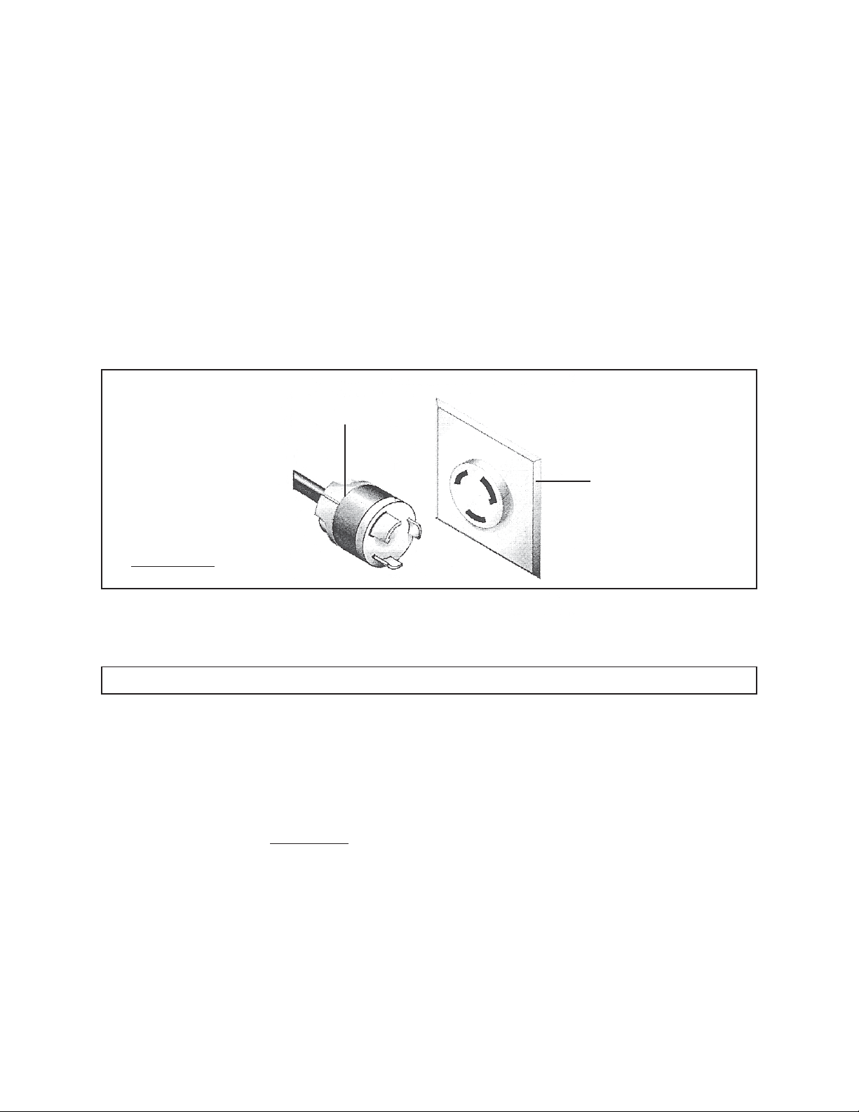
3. Your tool must be plugged into an appropriate outlet, properly installed
certified electrician
and grounded in accordance with all codes and ordinances.
The plug and outlet should look like that in the following illustration.
(See Figure A.)
220 VOLT, GROUNDED, 3-PRONG,
POWER CORD PLUG
(NOT INCLUDED)
220 VOLT, GROUNDED,
ELECTRICAL OUTLET
FIGURE A
by a
EXTENSION CORDS
1.
Grounded
tools require a three wire extension cord.
Double Insulated
tools
can use either a two or three wire extension cord.
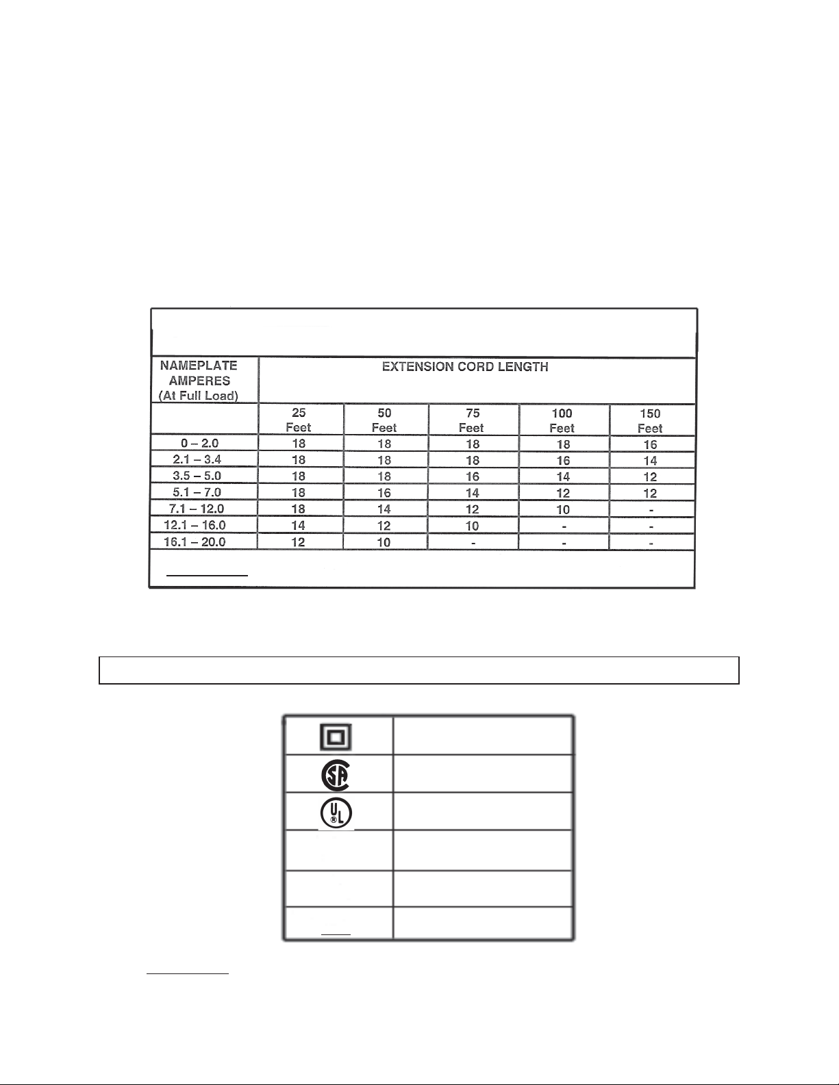
2. As the distance from the supply outlet increases, you must use a heavier gauge
extension cord. Using extension cords with inadequately sized wire causes a
serious drop in voltage, resulting in loss of power and possible tool damage.
(See Figure B, next page.)
3. The smaller the gauge number of the wire, the greater the capacity of the cord.
For example, a 14 gauge cord can carry a higher current than a 16 gauge cord.
(See Figure B.)
4. When using more than one extension cord to make up the total length, make
sure each cord contains at least the minimum wire size required.
(See Figure B.)
SKU 93491 For technical questions, please call 1-800-444-3353. Page 11
Page 12
5. If you are using an extension cord outdoors, make sure it is marked with the
suffix “W-A” (“W” in Canada) to indicate it is acceptable for outdoor use.
6. Make sure your extension cord is properly wired and in good electrical condition.
Always replace a damaged extension cord or have it repaired by a qualified
electrician before using it.
7. Protect your extension cords from sharp objects, excessive heat, and damp or
wet areas.
Recommended Minimum Wire Gauge For Extension Cords*
(220 Volt)
FIGURE B
* Based on limiting the line voltage drop
to five volts at 150% of the rated amperes.
SYMBOLOGY
Double Insulated
Canadian Standards
Association
Underwriters
Laboratories, Inc.
V ~
A
no
xxxx/min.
Volts Alternating Current
Amperes
No Load Revolutions
per Minute (RPM)
FIGURE C
SKU 93491 For technical questions, please call 1-800-444-3353. Page 12
Page 13
UNPACKING
When unpacking both boxes, check to make sure all the parts shown on the Parts Lists
on pages 52 through 61 are included. If any parts are missing or broken, please call
Harbor Freight Tools at the number shown on the cover of this manual as soon as possible.
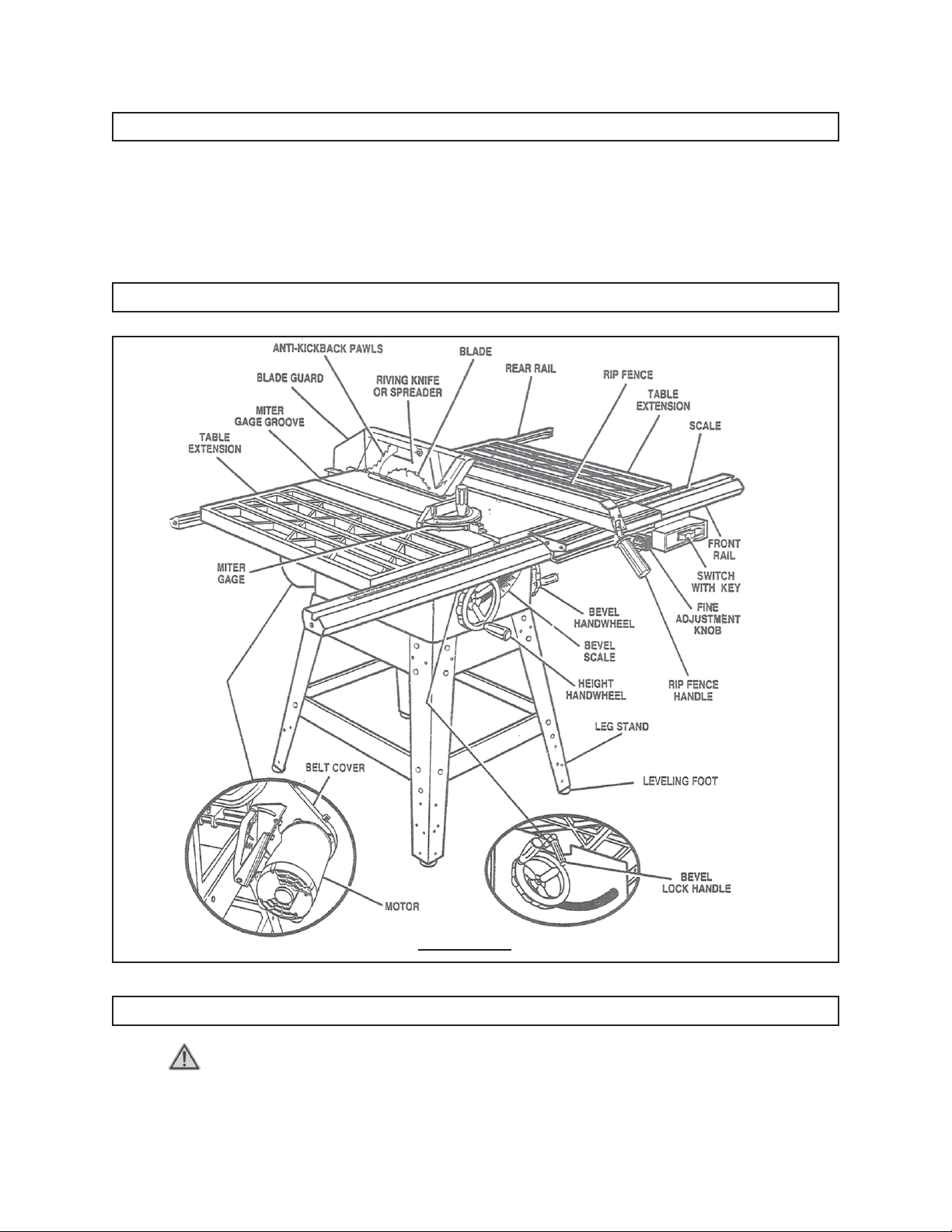
TABLE SAW FEATURES
FIGURE D
ASSEMBLY INSTRUCTIONS
1. CAUTION! Always make sure the Power Switch (8E) of the Table Saw is in
its “OFF” position and the tool is unplugged from its electrical outlet prior to
assembling the tool, adding any accessories, or making adjustments to the tool.
SKU 93491 For technical questions, please call 1-800-444-3353. Page 13
Page 14
To Assemble The Stand:
1. On a flat, dry, level surface lay out the following parts and hardware:
A. 4 Legs (4B).
B. 2 End Braces (6B).
C. 2 Side Braces (7B).
D. 2 Short Leg Braces (9B).
E. 2 Long Leg Braces (10B).
F. 24 Carriage Bolts (5B).
G. 4 Leveling Feet (1B).
H. 32 Washers (3B).
I. 32 Hex Nuts (2B).
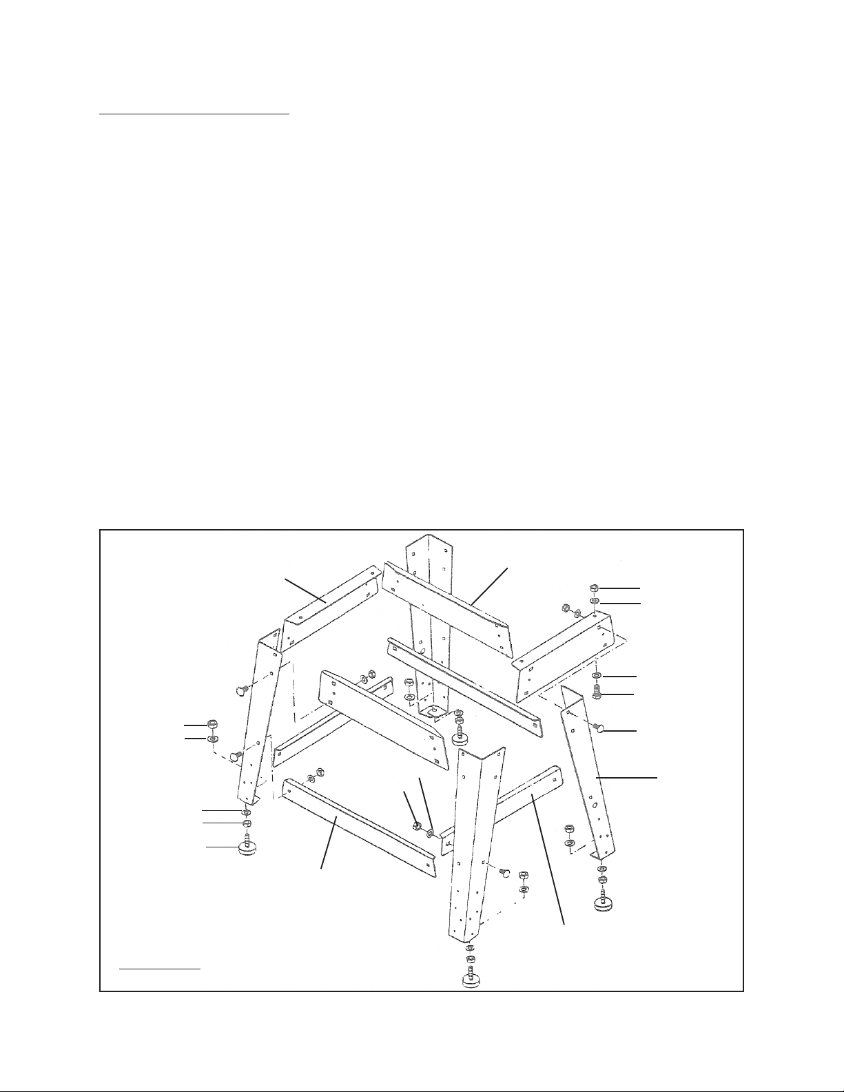
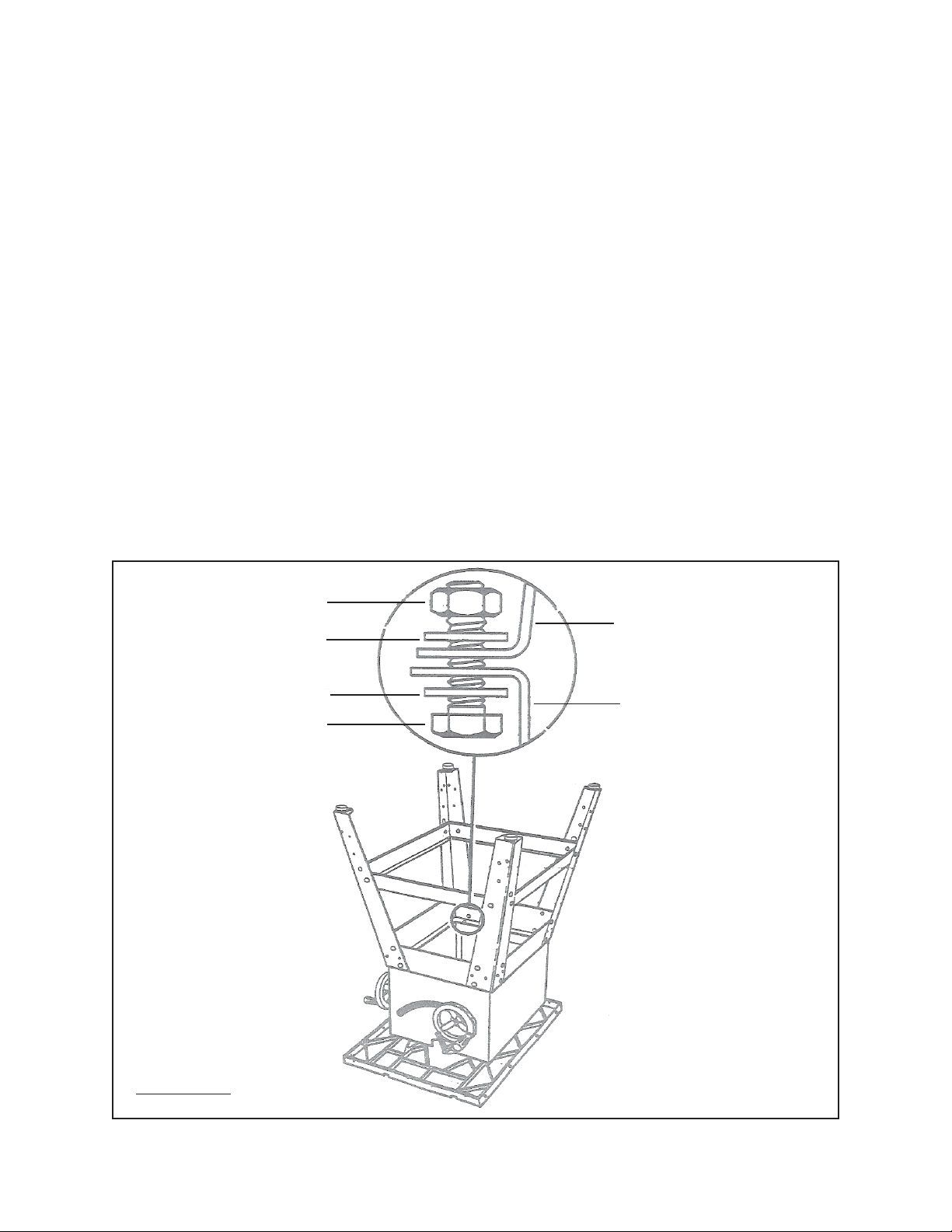
2. Place a Short Leg Brace (9B) inside two of the Legs (4B), with the Legs wide end
up. (See Figure E.)
3. Align the two large holes in the Short Leg Brace (9B) and the two Legs (4B).
Insert the Carriage Bolts (5B). Add Washers (3B) and Hex Nuts (2B) and hand
tighten. Repeat this procedure for the remaining Short Leg Brace and two Legs.
(See Figure E.)
HEX NUT (2B)
WASHER (3B)
WASHER (3B)
HEX NUT (2B)
LEVELING FOOT
(1B)
FIGURE E
END BRACE
(6B)
LONG LEG BRACE
(10B)
WASHER (3B)
HEX NUT (2B)
SIDE BRACE
(7B)
HEX NUT (2B)
WASHER (3B)
WASHER (3B)
HEX HEAD BOLT
(8B)
CARRIAGE BOLT
(5B)
LEG
(4B)
SHORT LEG BRACE
(9B)
SKU 93491 For technical questions, please call 1-800-444-3353. Page 14
Page 15
4. Attach a Long Leg Brace (10B) to two Legs (4B), using the Carriage Bolts (5B),
Washers (3B), and Hex Nuts (2B). Hand tighten only. Repeat this procedure for
the remaining Long Leg Brace and two Legs. (See Figure E.)
5. Use the same Steps to attach the End Braces (6B) and Side Braces (7B) to the
Legs (4B). (See Figure E.)
6. Tighten all the Hex Nuts (2B) using the Wrench (17-I) provided. (See Figure E.)
7. Place a Hex Nut (2B) and Washer (3B) on each Leveling Foot (1B). Insert the
threaded portion of the Leveling Feet upward through the bottom of each Leg
(4B). Cap with the remaining Washers (3B) and Hex Nuts (2B), but do not tighten
the top Hex Nut. (See Figure E.)
8. The location selected for the Table Saw must be level, dry, and well lighted. The
location must be capable of supporting the weight (approximately 310 pounds) of
the Table Saw and workpieces. There should also be room enough to allow
movement around the Saw with long pieces of woodstock.
9. Once located, set a carpenter’s level (not included) on the assembled Stand and
level the Stand from front to back and side to side. Adjust the Leveling Feet (1B)
with the Wrench (17-I). Then, tighten the top Hex Nut (2B) on the Leveling Feet.
(See Figure E.)
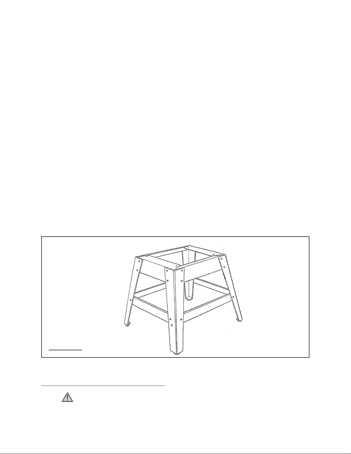
ASSEMBLED STAND
FIGURE F
To Attach The Saw Table To The Stand:
1. WARNING! Avoid injury. Do not lift the Saw Table without additional
help and a proper lifting device.
SKU 93491 For technical questions, please call 1-800-444-3353. Page 15
Page 16
2. This procedure will require use of the following hardware:
A. 4 Hex Bolts (8B).
B. 8 Hex Nuts (2B).
C. 8 Washers (3B).
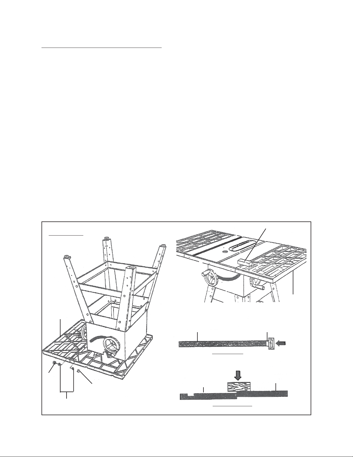
3. Check to make sure the Saw Blade (14-I) is fully retracted inside the Saw Table
(17H). Then, carefully set the Saw Table upside down on the floor surface,
(protect the Table top from being damaged). (See Figure G.)
4. Place the Stand upside down on the Saw Table Base (1G). Align the holes in the
Base with the holes in the End Braces (6B). (See Figure G.)
5. Place a Washer (3B) on a Hex Head Bolt (8B) and insert the Hex Head Bolt
upward through one of the previously aligned holes. Cap the Hex Head Bolt with
a Washer (3B) and Hex Nut (2B). Hand tighten only. (See Figure G.)
6. Repeat Step #5 for the three remaining holes. Then tighten all hardware with the
Wrench (17-I). NOTE: Leave the Table Saw sitting upside down.
(See Figure G.)
HEX NUT (2B)
WASHER (3B)
WASHER (3B)
HEX BOLT (8B)
STAND LEG (4B)
BASE (1G)
FIGURE G
SKU 93491 For technical questions, please call 1-800-444-3353. Page 16
Page 17
To Attach The Saw Table Extensions:
1. This procedure will require use of the following hardware:
A. 8 Hex Bolts (8B).
B. 8 Hex Nuts (2B).
C. 16 Washers (3B).
2. With the Table Saw sitting upside down, align the Extension Tables (5H) with the
Saw Table (17H) with the bevel edges in front. (See Figure H.)
3. Place a Washer (3B) on each Hex Bolt (8B). Attach the Extension Tables (5H) to
the Saw Table (17H) by inserting the Hex Bolts from the direction of the Saw
Tab le. (See Figure H.)
4. Place the remaining Washers (3B) and Hex Nuts (2B) on the Hex Bolts (8B).
Lightly tighten the Hex Bolts with the Wrench (17-I). (See Figure H.)
5. With additional personnel and a proper lifting device, stand the Table Saw upright, using the center Saw Table (17H). Do not grasp the Extension Tables (5H).
(See Figure I.)
FIGURE H
EXTENSION
TABLE
(5H)
HEX
NUT
(2B)
WASHER
(3B)
HEX BOLT
(8B)
SAW TABLE EDGE
SIDE VIEW
SAW TABLE EDGE
FRONT VIEW
WOOD BLOCK
EXTENSION
TABLE
(5H)
EXTENSION TABLE EDGE
TAP
HERE
TAP HERE
EXTENSION TABLE EDGE
SKU 93491 For technical questions, please call 1-800-444-3353. Page 17
Page 18
6. Stand at the front of the Table Saw and line up the front edges of the Saw Table
(17H) and Extension Tables (5H). (See Figure H.)
7. To align the Extension Tables (5H) with the Saw Table (17H) without damaging
the Table Saw, place a block of wood at the front of the Table Saw where the
Extension Table meets the Saw Table. Then, tap the block of wood with a
hammer. Check and repeat until the front edges are even. (See Figure H.)
8. Repeat this procedure for the rear edges of the Extension Tables (5H) Saw Table
(17H). When both the front and rear edges are even, tighten the Hex Bolts (8B)
with the Wrench (14-I). (See Figure H.)
To Attach The Rear Rail:
1. This procedure will require use of the following hardware:
A. 5 Square Head Bolts (10H).
B. 5 Hex Nuts (13H).
C. 5 Washers (12H).
2. At the back of the Saw Table (17H), place the Square Head Bolts (10H) in the
(12H)
EXTENSION
TABLE
(5H)
HEX NUT
(13H)
FIGURE I
SQUARE
HEAD
BOLT
(10H)
REAR RAIL
(3H)
REAR RAIL
SLOT
FOR
BOLT
REAR RAIL
INSTALLED
(3H)
SQUARE
HEAD
BOLT
(10H)
WASHER
2-1/2”
WASHER
(12H)
HEX NUT
(13H)
SKU 93491 For technical questions, please call 1-800-444-3353. Page 18
Page 19

holes in the edge of the Saw Table (17H) and Extension Tables (5H) so the heads
of the Square Head Bolts (10H) extend outward 1/2 inch.
(See Figure I, previous page.)
3. Under the Saw Table (17H), loosely attach the Washers (12H) and Hex Nuts
(13H) onto the Square Head Bolts (10H). Slide the slot on the Rear Rail (3H)
over the Square Head Bolts. Adjust each Bolt to move the Rail closely to the
Saw Table. (See Figure I.)
4. Position the Rear Rail (3H) so that the right hand edge extends 2-1/2” beyond the
Extension Tables (5H). (See Figure I.)
5. Push the Rear Rail (3H) against the Saw Table (17H) and Extension Tables (5H)
and tighten each Hex Nut (13H) with the Wrench (17-I). If the Rear Rail does not
slide easily over the Square Head Bolts (10H), realign the Extension Tables.
(See Figure I.)
To Attach The Front Rail:
1. This procedure will require use of the following hardware:
A. 5 Square Head Bolts (10H).
B. 5 Hex Nuts (13H).
C. 5 Washers (12H).
D. Right and Left End Caps (8H, 9H) for the Front Rail (7H).
E. 2 Tapping Screws (1H) for the End Caps.
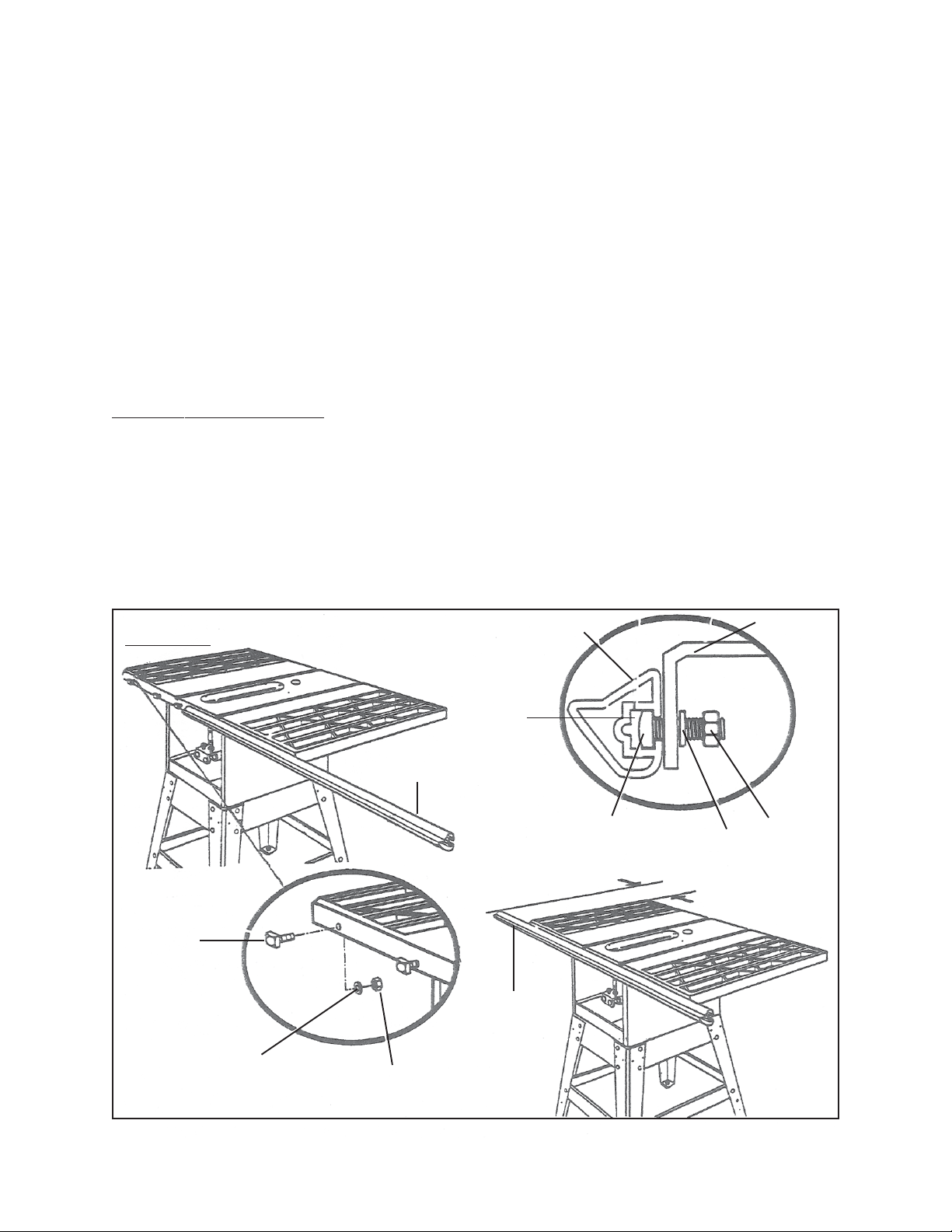
2. Insert the five Square Head Bolts (10H) into the Saw Table (17H) and Extension
Tables (5H) with the bolt heads extending out 1/2”. (See Figure J, next page.)
3. Under the Saw Table (17H) and Extension Tables (5H), loosely attach the
Washers (12H) and Hex Nuts (13H) onto the Square Head Bolts (10H).
(See Figure J.)
4. The back of the Front Rail (7H) has two slots. Slide the upper slot over the
Square Head Bolts (10H). (See Figure J.)
5. Align the Front Rail (7H) left to right -- match the 7-1/8” mark on the right Scale
(6H) to the right edge of the Saw Table (17H). (See Figure J.)
6. Snug the Front Rail (7H) against the Saw Table (17H) and Extension Tables (5H).
Then, finger-tighten each Hex Nut (13H) on the Saw Table and Extension Tables.
(See Figure J.)
SKU 93491 For technical questions, please call 1-800-444-3353. Page 19
Page 20

SCALE
(6H)
FRONT RAIL
(7H)
FRONT RAIL SLOT
HEX NUT
(13H)
SQUARE
HEAD
BOLT
(10H)
FIGURE J
WASHER
(12H)
HEX NUT
(13H)
FRONT RAIL (7H)
SAW TABLE
(17H)
SCALE
FRONT RAIL
WASHER
(12H)
TOP VIEW
EXTENSION
TABLE
(5H)
(6H)
(7H)
7-1/8” MARK (RIGHT SCALE)
To Align The Rip Fence And Front Rail:
1. NOTE: The Rip Fence Scale Indicator (20C) is installed on the right side of the
Rip Fence (10C), but can be removed and reinstalled on the left side if needed. If
a cutting operation requires placing the Rip Fence on the left side of the Saw
Blade (14-I), and relocating the Rip Fence Scale Indicator is necessary, simply
unscrew the Indicator and align and reattach it on the left side.
(See Assy. Diagram C.)
2. Hook the back of the Rip Fence (10C) over the Rear Rail (3H). Lower the front of
the Rip Fence into the groove on the Front Rail (7H).
(See Figure K, next page.)
SKU 93491 For technical questions, please call 1-800-444-3353. Page 20
Page 21

3. Slide the Rip Fence (10C) back and forth. The Rip Fence should move freely
with about 1/16” clearance between the Rip Fence and Saw Table (17H) surface.
If it doesn’t, loosen the Hex Nuts (13H) holding the Front Rail (7H) and adjust the
Front Rail up or down. (See Figure K.)
4. Remove the Rip Fence (10C) and repeat on the other side of the Saw Blade
(14-I). When the Rip Fence moves smoothly, tighten all the Hex Nuts (13H) with
the Wrench (14-I). (See Figure K.)
5. When finished, attach the Right and Left End Caps (8H, 9H) to the Front Rail
(7H), using the two Tapping Screws (1H). (See Figure K.)
RIP FENCE
RIP FENCE
(10C)
(10C)
FIGURE K
To Attach The Blade Guard:
HOOK OVER
REAR RAIL
HERE
REAR RAIL
(3H)
FRONT RAIL
(7H)
RIP FENCE
HANDLE
(37C)
RIGHT, LEFT
END CAPS
(8H, 9H)
TAPPING
SCREW
(1H)
1. This procedure will require use of the following hardware:
A. 2 Hex Bolts (2-I).
B. 3 Socket Head Screws (5D).
C. 2 Lock Washers (1-I).
D. 3 Washers (4D).
SKU 93491 For technical questions, please call 1-800-444-3353. Page 21
Page 22

2. Align the lower end of the Blade Guard Bracket (7D) and the threaded holes of
the Trunnion (36-I), and insert the two Hex Bolts (2-I) and Lock Washers (1-I).
Firmly tighten with the Wrench (17-I). (See Figure L.)
3. Temporarily remove the Throat Plate (15H). To do so, remove the four Set
Screws (14H). Then, lift the Throat Plate off the Saw Table (17H).
(See Figure L.)
TRUNNION
(36-I)
THROAT PLATE
BLADE GUARD
BRACKET
(7D)
HEX BOLT
(2-I)
FLAT HEAD
SCREW
(16H)
LOCK
WASHER
(1-I)
(15H)
SET SCREW
(14H)
FIGURE L
4. Place the Blade Guard Assembly (1D thru 13D) on the Saw Table (17H), aligning
the screw holes in the Riving Knife (6D) to the holes in the Blade Guard Bracket
(7D). Align the hole in the front of the Riving Knife Base (6D) with the screw hole
SOCKET HEAD SCREW (5D)
WASHER (4D)
RIVING KNIFE
(6D)
BLADE GUARD BRACKET
(7D)
BLADE GUARD
(10D)
FIGURE M
SKU 93491 For technical questions, please call 1-800-444-3353. Page 22
Page 23

in the Saw Table. NOTE: The screw hole is located under the slot in back of the
Throat Plate. (See Figure M, previous page.)
5. Insert two Socket Head Screws (5D) and two Washers (4D) in the two holes at
the back of the Riving Knife (6D) base. Then, firmly tighten with the Wrench
(14-I). (See Figure M.)
6. Insert the third Socket Head Screw (5D) and a Washer (4D) into the screw hole in
the Saw Table (17H) under the Throat Plate (15H). Then, firmly tighten with the
Wrench (14-I). (See Figure N.)
7. Replace the Throat Plate (15H) and its four Set Screws (14H). (See Figure L.)
BLADE GUARD
(10D)
SOCKET HEAD SCREW
FIGURE N
(5D)
WASHER
(4D)
RIVING KNIFE
(6D)
ANTI-KICKBACK PAWLS
(2D)
TRUNNION
(36-I)
To Check The Throat Plate For Proper Alignment:
1. WARNING! The Throat Plate (15H) must be even with the Saw Table (17H)
surface. If it is too high or too low, the workpiece can catch on uneven edges and
cause kickback. (See Figure O, next page.)
2. To make sure the Throat Plate (15H) is flush with the Saw Table (17H) surface,
loosen the Flat Head Screw (16H) that secures the Throat Plate and adjust the
four Set Screws (14H) on the Throat Plate with a 2mm Hex Key. Do not allow the
Throat Plate to bow up above the Saw Table surface.
(See Figure O.)
SKU 93491 For technical questions, please call 1-800-444-3353. Page 23
Page 24

2MM HEX KEY
FLAT HEAD SCREW
(16H)
SET SCREWS
(14H)
FRAMING SQUARE
(NOT INCLUDED)
THROAT PLATE
(15H)
FIGURE O
To Check Rip Fence And Saw Blade Alignment:
1. WARNING! Make sure the Power Switch (8E) is off, the Switch Key (7E) is
removed, and the Table Saw is unplugged from its electrical outlet. Failure to do
so could result in accidental starting, causing serious injury.
2. WARNING! Failure to align the Rip Fence (10C) to the Saw Blade (14-I)
can cause jams and kickback, resulting in personal injury.
3. Unlock the Rip Fence (10C) by raising its Handle (37C). Then slide the Rip
Fence to the Miter Gauge groove, which is parallel to the Saw Blade (14-I).
(See Figure S, next page.)
4. Place a framing square (not included) against the Saw Blade (14-I), with the long
end under the Rip Fence (10C) at the front. Then, note the distance.
(See Figure S.)
5. Move the framing square to the back and measure the length from the other end
of the Rip Fence (10C). (See Figure S.)
6. If the distances are different, loosen the four Adjustment Screws (11C) around
the Rip Fence Handle (37C) with a 6mm Hex Key (not included). Alternate the
order when loosening the Screws (remove the Screw opposite, not next to the
first one). (See Figure S.)
7. Hold the Rip Fence Handle (37C) against the Front Rail (7H) and align the Rip
Fence (10C) with the Saw Blade (14-I). (See Figure S.)
8. Retighten the four Adjustment Screws (11C) in alternating order and check the
alignment. (See Figure S.)
9. Repeat until the Rip Fence (10C) is aligned.
SKU 93491 For technical questions, please call 1-800-444-3353. Page 24
Page 25

SAW BLADE
(14-I)
MITER GAUGE GROOVE
RIP FENCE
(10C)
MITER GAUGE GROOVE
SAW
BLADE
(14-I)
RIP FENCE
(10C)
FRAMING
SQUARE
SCALE INDICATOR HOUSING
MITER GAUGE GROOVE
RIP FENCE HANDLE (37C)
(18C)
RIP FENCE
(10C)
ADJUSTMENT
SCREWS
(11C)
FIGURE S
FINE ADJUSTMENT KNOB (30C)
To Align The Riving Knife With The Saw Blade:
1. WARNING! Make sure the Power Switch (8E) is off, the Switch Key (7E) is
removed, and the Table Saw is unplugged from its electrical outlet. Failure to do
so could result in accidental starting, causing serious injury.
2. WARNING! It is important to install and adjust the Riving Knife (6D) correctly. Poor alignment could cause kickback and throw the workpiece at the
operator, resulting in severe personal injury.
3. The Riving Knife (6D) must be aligned and centered over the Saw Blade (14-I).
(See Figure P.)
4. Raise the Saw Blade (14-I) and the Blade Guard (10D). (See Figure P.)
SKU 93491 For technical questions, please call 1-800-444-3353. Page 25
Page 26

RIVING KNIFE
(6D)
ANTI-KICKBACK PAWLS
(2D)
SAW BLADE
(14-I)
FRAMING SQUARE
(NOT INCLUDED)
FIGURE P
5. Place a framing square (not included) or straight edge beside the Saw Blade
(14-I) on the left. (See Figure P, previous page.)
6. Loosen the front Socket Head Screw (5D) on the Riving Knife (6D) with a 5mm
Hex Key. (See Figure Q.)
7. Center the Riving Knife (6D) over the Saw Blade (14-I). (See Figure R.)
8. Firmly tighten the Socket Head Screw (5D) with a 5mm Hex Key.
(See Figure Q.)
RIVING KNIFE
(6D)
SOCKET
HEAD
SCREW
(5D)
SAW BLADE
(14-I)
FIGURE Q
BLADE GUARD
(10D)
RIVING KNIFE
(6D)
FRAMING SQUARE
(NOT INCLUDED)
VIEWED FROM TOP
OF SAW WITH RIVING
KNIFE SHOWN CENTERED
OVER SAW BLADE
FIGURE R
SAW BLADE
(14-I)
SKU 93491 For technical questions, please call 1-800-444-3353. Page 26
Page 27

10. To ensure proper self-alignment when positioning the Rip Fence (10C),
push the sides of the Scale Indicator Housing (18C) against the Front Rail (7H)
before locking the Rip Fence Handle (37C). (See Figure S, previous page.)
11. NOTE: For an even more precise adjustment, push in on the Fine Adjustment
Knob (30C) and turn to move the Rip Fence (10C) to the desired location.
(See Figure S.)
To Replace The Saw Blade:
1. WARNING! Make sure the Power Switch (8E) is off, the Switch Key (7E) is
removed, and the Table Saw is unplugged from its electrical outlet. Failure to do
so could result in accidental starting, causing serious injury.
2. CAUTION! To avoid accidental cuts, make sure to wear heavy duty work
gloves when replacing the Saw Blade (14-I). (See Figure T, next page.)
3. Raise the Blade Guard (10D) and remove the Throat Plate (15H). To remove,
loosen the Flat Head Screw (16H) at the front with a phillips screwdriver (not
included) and lift the front end. Pull out on the Throat Plate toward the front end.
(See Figure L.)
4. Raise the Saw Blade (14-I) to its highest position by turning the Height Hand
Wheel (4G) clockwise. Angle the Saw Blade straight up by loosening the Bevel
Lock Handle (19-I) and turning the Bevel Hand Wheel (4G). Wedge a piece of
scrap wood against the front of the Saw Blade.
(See Figure D page 13, and Figure T, next page.)
5. Loosen the Blade Nut (16-I) with the Wrench (17-I) provided. Remove the Blade
Nut and Outer Blade Washer (15-I). Then, remove the scrap wood and Saw
Blade (14-I). (See Figure T.)
6. To install a 12” diameter Saw Blade (14-I), place the new Saw Blade on the Arbor
Shaft (13-I) with its teeth pointing
Then, wedge a piece of scrap wood at the back of the Saw Blade.
(See Figure T.)
7. CAUTION! The teeth of the Saw Blade (14-I) MUST point downward
toward the front of the Table Saw to work properly. If not, damage to the Saw
Blade, Table Saw, and/or workpiece can occur. (See Figure T.)
8. Place the Outer Blade Washer (15-I) and Blade Nut (16-I) on the Arbor Shaft
(13-I). Make sure the dome side of the Outer Blade Washer faces out from the
Saw Blade (14-I) and that all parts are snug against the Arbor Housing. Then,
downward
toward the front of the Table Saw.
SKU 93491 For technical questions, please call 1-800-444-3353. Page 27
Page 28

tighten the Blade Nut securely. (See Figure T.)
9. Remove the scrap wood, and rotate the Saw Blade (14-I) by hand to make sure it
turns freely. (See Figure T.)
10. Lower the Saw Blade (14-I) and slip the Throat Plate (15H) into the opening in
the Saw Table (17H). Push the Throat Plate toward the back of the Table Saw to
engage the Spring Clip. Retighten the Flat Head Screw (16H). If the Throat
Plate is not flush with the Saw Table, adjust the Set Screws (14H) with a 2mm
Hex Key. Do not allow the Throat Plate to bow up above the Saw Table surface.
(See Figure L page 22, and Figure O page 24.)
To Parallel The Saw Blade To The Miter Gauge Groove:
1. WARNING! Make sure the Power Switch (8E) is off, the Switch Key (7E) is
removed, and the Table Saw is unplugged from its electrical outlet. Failure to do
so could result in accidental starting, causing serious injury.
2. WARNING! The Saw Blade (14-I) MUST parallel the Miter Gauge Groove
BLADE GUARD
SAW BLADE AT
HIGHEST
POSITION
WOOD
(10D)
NEW SAW BLADE (14-I)
TEETH DOWN AT FRONT
TO
LOOSEN
SAW BLADESCRAP
SCRAP WOOD
OUTER
BLADE
WASHER
(15-I)
BLADE NUT
(16-I)
ARBOR
SHAFT
(13-I)
TO
TIGHTEN
SAW BLADE
FIGURE T
SKU 93491 For technical questions, please call 1-800-444-3353. Page 28
Page 29

so the wood does not bind, resulting in kickback.
3. IMPORTANT: Do not loosen any screws for this adjustment until you have
checked with a framing square and made test cuts to be sure adjustments are
necessary.
4. To parallel the Saw Blade (14-I) to the Miter Gauge Groove, lift the Blade Guard
(10D). Then, turn the Height Hand Wheel (4G) to raise the Saw Blade all the way
up. (See Figure D, page 13.)
5. Draw a mark beside one of the Saw Blade (14-I) teeth at the front of the Saw
Blade. Place a framing square beside the Saw Blade on the mark. Make sure
the framing square is between the teeth and flat against the Saw Blade. Then,
measure the distance to the right Miter Gauge Groove.
(See Figure U, next page.)
6. Turn the Saw Blade (14-I) so the marked tooth is at the back of the Saw Table
(17H). (See Figure U.)
7. Move the framing square to the rear of the Saw Table (17H) and again measure
the distance to the right Miter Gauge Groove. If the distances are the same, the
Saw Blade (14-I) and the Miter Gauge Groove are parallel. (See Figure U.)
8. If the distances measured are different, remove the Throat Plate (15H) from the
Saw Table (17H) in order to gain access to the Table Brackets (7-I) for adjustment
purposes. (See Figure U.)
9. Lower the Saw Blade (14-I) completely with the Height Hand Wheel (4G). You
can then access the Table Brackets (7-I) through the Throat Plate opening.
(See Figure U.)
10. From the back, loosen the three Hex Head Bolts (9-I) holding the Rear Table
Bracket (7-I) with a 12mm wrench (not included). (See Figure U.)
11. If the Saw Blade (14-I) was too far from the Miter Gauge Groove, move the Rear
Table Bracket (7-I) toward the Miter Gauge Groove. Tap with a wood block and
hammer. (See Figure U.)
12. If the Saw Blade (14-I) was too close to the Miter Gauge Groove, back the Rear
Table Bracket (7-I) with a block of wood and hammer. (See Figure U.)
13. Tighten the three Hex Head Bolts (9-I). Raise the Saw Blade (14-I) and re-check.
(See Figure U.)
14. Repeat the above Steps until the Saw Blade (14-I) is parallel to the Miter Gauge
SKU 93491 For technical questions, please call 1-800-444-3353. Page 29
Page 30

Groove. (See Figure U.)
15. If the Saw Blade (14-I) still is not parallel, adjust the Front Table Bracket (7-I).
(See Figure U.)
16. Tilt the Saw Blade (14-I) to 45 degrees, using the Bevel Lock Handle (19-I) and
Bevel Hand Wheel (4G). (See Figure U.)
17. From the back of the Table Saw, loosen the three Hex Head Bolts (9-I) holding
the Front Table Bracket (7-I)
and
loosen the three Hex Head Bolts (9-I) holding
the Rear Table Bracket (7-I) . (See Figure U.)
18. Reposition the Saw Blade (14-I) to 90 degrees with the Bevel Lock Handle (19-I)
and Bevel Hand Wheel (4G). (See Figure U.)
19. Lower the Saw Blade (14-I) and move the Front and Rear Table Brackets (7-I) as
needed. Then, retighten all six Hex Head Bolts (9-I). (See Figure U.)
20. Raise the Saw Blade (14-I) and recheck. Repeat until the Saw Blade (14-I) is
parallel to the Miter Gauge Groove. (See Figure U.)
21. When finished, reinstall the Throat Plate (15H) on the Saw Table (17H), making
sure the Throat Plate is flush with the Saw Table. (See Figure U.)
NOTE: BLADE GUARD (10D)
IS NOT SHOWN FOR CLARITY
MARKED TOOTH
AT FRONT
FRAMING SQUARE
(NOT INCLUDED)
MITER GAUGE
GROOVE
MARKED TOOTH AT BACK
REAR TABLE BRACKET (7-I)
REAR
HEX
HEAD
BOLT (9-I)
FRONT
TABLE BRACKET (7-I)
FRAMING
SQUARE
(NOT INCLUDED)
REAR HEX HEAD BOLT (9-I)
FRONT HEX HEAD BOLT (9-I)
FIGURE U
(VIEWED FROM BELOW)
SKU 93491 For technical questions, please call 1-800-444-3353. Page 30
Page 31

To Set The Bevel Stops And Indicator:
1. WARNING! Make sure the Power Switch (8E) is off, the Switch Key (7E) is
removed, and the Table Saw is unplugged from its electrical outlet. Failure to do
so could result in accidental starting, causing serious injury.
2. NOTE: The Bevel Scale (10G) should show 0 degrees when the Saw Blade
(14-I) is set at 90 degrees. Also, the Bevel Scale should show 45 degrees when
the Saw Blade is set at a 45 degree tilt. (See Figure V.)
3. Raise the Saw Blade (14-I) all the way up by turning the Height Hand Wheel
(4G). (See Figure V.)
4. Loosen the Bevel Lock Handle (19-I) and turn the Bevel Hand Wheel (4G) clock-
wise to tilt the Saw Blade (14-I). Reverse it and turn the Bevel Hand Wheel
counterclockwise until it stops. (See Figure V.)
5. Check the Saw Blade (14-I) angle with a combination square (not included). Do
not allow the square to touch a blade tooth-check against blade blank. The Saw
Blade should be at 90 degrees and the Bevel Scale Indicator at 0 degree. NOTE:
The Scale Indicator is the plastic plate on Bevel Scale (10G). (See Figure V.)
6. If the Scale Indicator does not point to 0 degree loosen the Scale Indicator Screw
with a screwdriver (not included). Adjust the Scale. Then, retighten the Screw.
(See Figure V.)
7. If the Saw Blade (14-I) angle is wrong, adjust the 90 Degree Set Screw (18H).
Start by turning the 90 Degree Set Screw three or four times with a 4mm hex key.
(See Figure V.)
BEVEL
LOCK
HANDLE
(19-I)
(NOT SHOWN)
HEIGHT
HAND WHEEL
(4G)
BEVEL
SCALE
INDICATOR
4MM HEX KEY
BEVEL HAND WHEEL
(4G)
90 DEGREE
SET SCREW
(18H)
45 DEGREE
SET SCREW
(18H)
FIGURE V
HEIGHT HAND WHEEL
(4G)
SKU 93491 For technical questions, please call 1-800-444-3353. Page 31
Page 32

8. Turn the Bevel Hand Wheel (4G) clockwise once, then back counterclockwise to
square the Saw Blade (14-I) with the Saw Table (17H). (See Figure V.)
9. Tighten the 90 Degree Set Screw (18H) and recheck that the Saw Blade (14-I) is
square in a 90 degree position. If not, repeat. When the Saw Blade is square,
check the Bevel Scale Indicator. If it is not at zero, reset the Indicator as before.
(See Figure V.)
10. Check the 45 degree setting. Tilt the Saw Blade (14-I) with the Bevel Hand
Wheel (4G) as far as it will go to the left. Place a combination square against the
SPLITTER (315)
Saw Blade, making sure the square is not against one of the blade teeth. If the
Saw Blade is not at 45 degrees, unscrew the 45 Degree Set Screw (18H). Turn
the Bevel Hand Wheel until the Saw Blade is correct. Then, tighten the 45
Degree Set Screw. Recheck and repeat if necessary. (See Figure V.)
11. Check that the Bevel Scale (10G) Indicator is at 45 degrees. If not, loosen the
Indicator with a screwdriver. Adjust, and retighten the Screw. (See Figure V.)
To Adjust The Miter Gauge:
1. NOTE: The Miter Gauge provides close accuracy in angled cuts. For very close
tolerances, test cuts are recommended.
2. You can set the Miter Gauge at 0 degree and plus or minus 45 degrees with the
Miter Gauge Stop Pin (8A) and adjustable Stop Screws (11A). (See Figure W.)
3. Loosen the Miter Gauge Knob (2A) and pull out on the Stop Pin (8A) to rotate the
Miter Gauge Base (4A) past the Stop Screws (11A). (See Figure W.)
4. Loosen the Hex Nut (12A) of the 0 Degree Stop Screw (11A) at the Stop Pin (8A)
MITER GAUGE KNOB (2A)
MITER GAUGE ROD (10A)
MITER GAUGE BASE (4A)
45 DEGREE STOP SCREW (11A)
0 DEGREE STOP SCREW (11A)
FIGURE W
HEX NUT (12A)
STOP PIN (8A)
SKU 93491 For technical questions, please call 1-800-444-3353. Page 32
Page 33

with an 8mm wrench (not included). (See Figure W.)
5. Place a 90 degree square against the Miter Gauge Rod (10A) and the Miter
Gauge Base (4A). (See Figure W.)
6. If the Miter Gauge Rod (10A) is not square, loosen the Knob (2A). Adjust the
Rod, and retighten the Knob. (See Figure W.)
7. Adjust the 0 Degree Stop Screw (11A) until it rests against the Stop Pin (8A).
(See Figure W.)
8. Adjust the plus and minus 45 Degree Stop Screws (11A) by using a 45 degree
triangle (not included) and following the Steps above. (See Figure W.)
Removing And Replacing The Throat Plate:
1. WARNING! Make sure the Power Switch (8E) is off, the Switch Key (7E) is
removed, and the Table Saw is unplugged from its electrical outlet. Failure to do
so could result in accidental starting, causing serious injury.
2. To remove the Throat Plate (15H), loosen the Flat Head Screw (16H) holding the
Throat Plate with a phillips screwdriver (not included). Then, lift the front end of
the Throat Plate and pull out toward the front of the Table Saw. (See Figure X.)
3. To reinstall the Throat Plate (15H), place the Throat Plate in the opening in the
Saw Table (17H). Push the Throat Plate toward the rear of the Table Saw to
engage the Spring Clip. NOTE: The key slot in the Throat Plate will drop over
the Flat Head Screw (16H). (See Figure X.)
THROAT PLATE
KEY SLOT
(15H)
SET SCREWS
(18H)
SPRING CLIP
SAW TABLE
(17H)
FIGURE X
FLAT HEAD SCREW (16H)
SKU 93491 For technical questions, please call 1-800-444-3353. Page 33
Page 34

4. Check that the Throat Plate (15H) is even with the Saw Table (17H). If not, adjust
the four corner Set Screws (18H) with a 2mm hex key.
(See “To Check The Throat Plate For Proper Alignment” section on page 23.)
5. Securely tighten the Flat Head Screw (16H). Do not allow the Throat Plate (15H)
to bow up above the Saw Table (17H) surface. (See Figure X.)
OPERATING INSTRUCTIONS
Cutting Aids:
1. Pushsticks (not included) are devices used for safely pushing a workpiece
through the Saw Blade (14-I) instead of using your hands. Pushsticks can be
made in various sizes and shapes from scrap wood. The pushstick must be
narrower than the workpiece, with a 90 degree notch on one end and shaped with
a grip on the other end. (See Figure Y.)
2. A pushblock (not included) has a handle fastened by
underside. Use a pushblock on non-through cuts. (See Figure Y.)
PUSHSTICKS
recessed
screws from the
PUSHBLOCKS
FIGURE Y
SKU 93491 For technical questions, please call 1-800-444-3353. Page 34
Page 35

Resetting The Thermal Overload Protector:
1. The Table Saw is equipped with an overload protector to shut off the Saw when a
power circuit limit is reached and the Motor (7F) temperature begins to rise.
(See Figure AA.)
2. If the Motor (7F) overheats, the overload protector will shut down the power. Use
the Steps below to restart the Table Saw: (See Figure AA.)
3. WARNING! If the overload protector shuts off, immediately turn the Power
Switch (8E) off and remove anything contacting the Saw Blade (14-I) to prevent
the risk of injury. When the Motor (7F) cools down, it could unexpectedly restart
the Saw Blade, throwing an object or cutting your hand if you are touching the
Saw Blade.
4. Allow time for the Motor (7F) to cool. (You may have to let the Motor cool for as
long as it had run before the overload protector shut it off.)
5. While the Motor (7F) is cooling, refer to the “TROUBLESHOOTING” section in
this manual to try to determine the reason for overload. If possible, correct the
problem before resuming operation.
6. Press on the red Motor Reset Button on the end of the Motor (7F). If the Motor
has cooled enough, you will hear a “click”. If you do not hear a “click”, allow the
Motor to cool longer. (See Figure AA.)
7. When you hear the “click”, the Motor (7F) has been reset and you can continue
the cutting operation. (See Figure AA.)
THE MOTOR SHOULD BE BLOWN OUT
OR VACUUMED FREQUENTLY TO PREVENT
SAWDUST BUILD-UP WHICH CAN INTERFERE
WITH MOTOR COOLING.
MOTOR
(7F)
NOTE:
FIGURE AA
MOTOR RESET BUTTON
SKU 93491 For technical questions, please call 1-800-444-3353. Page 35
Page 36

The Power Switch:
1. The Power Switch (8E) is equipped with a Switch Key to help prevent
unauthorized use of the Table Saw. (See Figure BB.)
2. To turn on the Table Saw, insert the Switch Key into the Power Switch (8E), and
pull out on the Power Switch to turn on the Table Saw. To turn off the Table Saw,
push in on the Power Switch and remove the Switch Key. Make sure to store the
Switch Key in a safe location, out of reach of children and other unauthorized
people. (See Figure BB.)
POWER SWITCH
(8E)
INSERT SWITCH KEY
POWER SWITCH ON
FIGURE BB
POWER SWITCH OFF
Making A Cross Cut:
1. WARNING! Make sure the Blade Guard (10D) is lowered over the Saw
Blade (14-I) and is working properly to prevent possible injury.
2. Set the Saw Blade (14-I) to the correct depth for the workpiece by turning the
Height Hand Wheel (4G). (See Figure CC, next page.)
3. Set the Miter Gauge to 0 degrees. Make sure the Miter Gauge Knob (2A) is securely tightened. (See Figure CC.)
4. Place a support (not included) the same height as the Saw Table (17H) behind
the Table Saw for large workpieces. (See Figure II, page 45.)
5. The Miter Gauge may be used in either of the two Miter Gauge Grooves in the
SKU 93491 For technical questions, please call 1-800-444-3353. Page 36
Page 37

Saw Table (17H). When using the left Groove, hold the workpiece firmly against
the Miter Gauge Base (4A) with your left hand and grip the Knob (2A) with your
right hand. When using the right Groove, hold the workpiece firmly against the
Miter Gauge Base with your right hand and grip the Knob with your left hand.
(See Figure CC.)
6. Make sure the workpiece is not touching the Saw Blade (14-I).
7. Plug the Power Cord Plug into the nearest 220 volt, grounded, electrical outlet.
Then, insert the Switch Key and pull the Power Switch (8E) to its “ON” position.
(See Figure BB.)
8. Allow the Saw Blade (14-I) to spin up to full speed before feeding the workpiece
into the Saw Blade with the Miter Gauge. (See Figure CC.)
9. Make sure to
gradually
feed the workpiece into the Saw Blade (14-I). Do not
attempt to force the Table Saw to cut faster or greater than its capacity.
(See Figure CC.)
10. When the cut is completed, press the Power Switch (8E) to its “OFF” position and
remove the Switch Key. Then, unplug the Power Cord Plug from its electrical
outlet. (See Figure BB.)
CROSS CUT
WHEN MITER GAUGE IS ON
LEFT SIDE OF SAW BLADE
PLACE RIGHT HAND ON
MITER GAUGE KNOB (2A) HERE.
PLACE LEFT HAND ON
WORKPIECE AND MITER
GAUGE BASE (4A) HERE.
FIGURE CC
SKU 93491 For technical questions, please call 1-800-444-3353. Page 37
Page 38

Making A Rip Cut:
1. WARNING! Make sure the Blade Guard (10D) is lowered over the Saw
Blade (14-I) and is working properly to prevent possible injury. Make sure that
saw blade is at correct height for the workpiece to be cut.
2. WARNING! NEVER stand directly in the line of the cut. Stand to the side
of the Table Saw to reduce the risk of injury.
3.
WARNING! NEVER push a small piece of wood into the Saw Blade (14-I)
with your hand. For small pieces of wood, use a pushstick to move wood into
and past the Saw Blade.
4. Remove the Miter Gauge and attach the Rip Fence over the Front and Rear Rails
(7H, 3H). (See Figure DD.)
5. Place a support (not included) the same height as the Saw Table (17H) behind
the Table Saw for cut workpieces.
6. Make sure the workpiece is not touching the Saw Blade (14-I).
7. Plug the Power Cord Plug into the nearest 220 volt, grounded, electrical outlet.
Then, insert the Switch Key and pull the Power Switch (8E) to its “ON” position.
(See Figure BB.)
RIP CUT
SCALE (6H)
SAW BLADE
(14-I)
RIP FENCE
FIGURE DD
SKU 93491 For technical questions, please call 1-800-444-3353. Page 38
Page 39

8. Allow the Saw Blade (14-I) to spin up to full speed before feeding the workpiece
into the Saw Blade. (See Figure DD.)
9. Make sure to
gradually
feed the workpiece into the Saw Blade (14-I). Do not
attempt to force the Table Saw to cut faster or greater than its capacity.
(See Figure DD.)
10. When the cut is completed, press the Power Switch (8E) to its “OFF” position and
remove the Switch Key. Then, unplug the Power Cord Plug from its electrical
outlet. (See Figure BB.)
Making A Miter Cut:
1. WARNING! Make sure the Blade Guard (10D) is lowered over the Saw
Blade (14-I) and is working properly to prevent possible injury.
2. The Miter Gauge may be used in either of the two Miter Gauge Grooves in the
Saw Table (17H). When using the left Groove, hold the workpiece firmly against
the Miter Gauge Base (4A) with your left hand and grip the Knob (2A) with your
right hand. When using the right Groove, hold the workpiece firmly against the
Miter Gauge Base with your right hand and grip the Knob with your left hand.
(See Figure EE.)
3. Make sure the Saw Blade (14-I) is at the correct height for the workpiece. To
change the Saw Blade height, turn the Height Hand Wheel (4G).
(See Figure EE.)
MITER CUT
SAW BLADE (14-I) STRAIGHT
FIGURE EE
MITER GAUGE ANGLED
HEIGHT HAND WHEEL (4G)
BEVEL HAND WHEEL (4G)
SKU 93491 For technical questions, please call 1-800-444-3353. Page 39
Page 40

4. If the Saw Blade (14-I) is not at 90 degrees to the Saw Table (17H), loosen the
Bevel Lock Handle (19-I) and turn the Bevel Hand Wheel (4G). Then, retighten
the Bevel Lock Handle. (See Figure EE.)
5. To set the wood angle, loosen the Miter Gauge Knob (2A). Set the angle with the
Indicator on the Miter Gauge Base (4A). Then, retighten the Miter Gauge Knob.
(See Figure EE.)
6. Place a support (not included) the same height as the Saw Table (17H) behind
the Table Saw for cut workpieces.
7. Make sure the workpiece is not touching the Saw Blade (14-I).
8. Plug the Power Cord Plug into the nearest 220 volt, grounded, electrical outlet.
Then, insert the Switch Key and pull the Power Switch (8E) to its “ON” position.
(See Figure BB.)
9. Allow the Saw Blade (14-I) to spin up to full speed before feeding the workpiece
into the Saw Blade. (See Figure EE.)
10. Hold the workpiece firmly against the Miter Gauge, and push the workpiece into
the Saw Blade (14-I). (See Figure EE.)
11. Make sure to
attempt to force the Table Saw to cut faster or greater than its capacity.
(See Figure EE.)
12. When the cut is completed, press the Power Switch (8E) to its “OFF” position and
remove the Switch Key. Then, unplug the Power Cord Plug from its electrical
outlet. (See Figure BB.)
gradually
feed the workpiece into the Saw Blade (14-I). Do not
Making A Bevel Cross Cut:
1. WARNING! Make sure the Blade Guard (10D) is lowered over the Saw
Blade (14-I) and is working properly to prevent possible injury.
2. When using the left Groove, hold the workpiece firmly against the Miter Gauge
Base (4A) with your left hand and grip the Knob (2A) with your right hand. When
using the right Groove, hold the workpiece firmly against the Miter Gauge Base
with your right hand and grip the Knob with your left hand.
(See Figure FF, next page.)
3. Raise the Rip Fence Handle (37C) and remove the Rip Fence.
4. Set the Saw Blade (14-I) angle by loosening the Bevel Lock Handle (19-I) and
SKU 93491 For technical questions, please call 1-800-444-3353. Page 40
Page 41

turning the Bevel Hand Wheel (4G) until the Bevel Scale (10G) on the cabinet
front reads zero. Then, retighten the Bevel Lock Handle (19-I). Make sure that
saw blade is at correct height for the workpiece to be cut. (See Figure FF.)
5. If necessary, loosen the Miter Gauge Knob (2A) and set the Miter Gauge to 0
degrees. Then, retighten the Miter Gauge Knob. (See Figure FF.)
6. Make sure the workpiece is not touching the Saw Blade (14-I).
7. Plug the Power Cord Plug into the nearest 220 volt, grounded, electrical outlet.
Then, insert the Switch Key and pull the Power Switch (8E) to its “ON” position.
(See Figure BB.)
8. Allow the Saw Blade (14-I) to spin up to full speed before feeding the workpiece
into the Saw Blade. (See Figure FF.)
9. Hold the workpiece firmly against the Miter Gauge, and push the workpiece into
the Saw Blade (14-I). (See Figure FF.)
10. Make sure to
gradually
feed the workpiece into the Saw Blade (14-I). Do not
attempt to force the Table Saw to cut faster or greater than its capacity.
(See Figure FF.)
11. When the cut is completed, press the Power Switch (8E) to its “OFF” position and
remove the Switch Key. Then, unplug the Power Cord Plug from its electrical
outlet. (See Figure BB.)
BEVEL CROSS CUT
SAW BLADE
(14-I)
ANGLED
MITER GAUGE STRAIGHT
BEVEL HAND WHEEL (4G)
BEVEL LOCK
HANDLE
(19-I)
BEVEL LOCK HANDLE
(NOT SHOWN)
FIGURE FF
(VIEWED FROM THE FRONT, BELOW THE SAW TABLE)
SKU 93491 For technical questions, please call 1-800-444-3353. Page 41
Page 42

Making A Bevel Rip Cut:
1. WARNING! Make sure the Blade Guard (10D) is lowered over the Saw
Blade (14-I) and is working properly to prevent possible injury.
2. WARNING! When making a bevel rip cut, the Rip Fence must be on the
right side of the Saw Blade (14-I). If not, the Rip Fence could trap the
workpiece, possibly causing kickback and resulting in injury. (See Figure GG.)
3. WARNING! NEVER stand directly in the line of the cut. Stand to the side
of the Table Saw to reduce the risk of injury.
4. WARNING! NEVER push a small piece of wood into the Saw Blade (14-I)
with your hand. For small pieces of wood, use a pushstick to move wood into
and past the Saw Blade.
5. Set the Saw Blade (14-I) by loosening the Blade Lock Handle (19-I) and turning
the Bevel Hand Wheel (4G). Then, retighten the Blade Lock Handle. Make sure
that saw blade is at correct height for the workpiece to be cut.
6. Attach the Rip Fence on the right side of the Saw Blade (14-I) at the correct
distance from the Saw Blade for the cut. If necessary, use the Fine Adjustment
Knob (30C) on the Front Rail (7H). (See Figure GG.)
7. Place a support (not included) the same height as the Saw Table (17H) behind
BEVEL RIP CUT
SAW BLADE
(14-I)
ANGLED
SCALE (6H)
RIP FENCE ON RIGHT
SIDE OF SAW BLADE
FINE ADJUSTMENT KNOB
(30C)
FIGURE GG
SKU 93491 For technical questions, please call 1-800-444-3353. Page 42
Page 43

the Table Saw for cut workpieces.
8. Make sure the workpiece is not touching the Saw Blade (14-I).
9. Plug the Power Cord Plug into the nearest 220 volt, grounded, electrical outlet.
Then, insert the Switch Key and pull the Power Switch (8E) to its “ON” position.
(See Figure BB.)
10. Allow the Saw Blade (14-I) to spin up to full speed before feeding the workpiece
into the Saw Blade. (See Figure GG.)
11. Make sure to
attempt to force the Table Saw to cut faster or greater than its capacity.
(See Figure GG.)
12. When the cut is completed, press the Power Switch (8E) to its “OFF” position and
remove the Switch Key. Then, unplug the Power Cord Plug from its electrical
outlet. (See Figure BB.)
gradually
feed the workpiece into the Saw Blade (14-I). Do not
Making A Compound (Bevel) Miter Cut:
1. WARNING! Make sure the Blade Guard (10D) is lowered over the Saw
Blade (14-I) and is working properly to prevent possible injury.
2. WARNING! When the Saw Blade (14-I) is angled to the left, the Miter Gauge
must be on the right side of the Saw Blade. If not, the Miter Gauge could trap the
workpiece, possibly causing kickback and resulting in injury.
(See Figure HH, next page.)
3. Remove the Rip Fence, and install the Miter Gauge on the right side of the Saw
Blade (14-I).
4. Set the Saw Blade (14-I) angle and height by loosening the Bevel Lock Handle
(19-I) and turning the Height and Bevel Hand Wheels (4G). Then, retighten the
Bevel Lock Handle. (See Figure HH.)
5. Set the wood angle by loosening the Miter Gauge Knob (2A) and setting it to the
desired angle. Then, retighten the Miter Gauge Knob. (See Figure HH.)
6. Place a support (not included) the same height as the Saw Table (17H) behind
the Table Saw for cut workpieces.
7. Make sure the workpiece is not touching the Saw Blade (14-I).
SKU 93491 For technical questions, please call 1-800-444-3353. Page 43
Page 44

8. Plug the Power Cord Plug into the nearest 220 volt, grounded, electrical outlet.
Then, insert the Switch Key and pull the Power Switch (8E) to its “ON” position.
(See Figure BB.)
9. Allow the Saw Blade (14-I) to spin up to full speed before feeding the workpiece
into the Saw Blade. (See Figure HH.)
10. Hold the workpiece firmly against the Miter Gauge, and push the workpiece into
the Saw Blade (14-I). (See Figure HH.)
11. Make sure to
gradually
feed the workpiece into the Saw Blade (14-I). Do not
attempt to force the Table Saw to cut faster or greater than its capacity.
(See Figure HH.)
12. When the cut is completed, press the Power Switch (8E) to its “OFF” position and
remove the Switch Key. Then, unplug the Power Cord Plug from its electrical
outlet. (See Figure BB.)
COMPOUND (BEVEL) MITER CUT
PLACE RIGHT HAND
ON WORKPIECE AND
MITER GAUGE HERE.
WHEN MITER GAUGE IS ON RIGHT SIDE
OF SAW BLADE PLACE LEFT HAND ON
MITER GAUGE KNOB HERE.
FIGURE HH
Making A Large Panel Cut:
1. WARNING! Make sure the Blade Guard (10D) is lowered over the Saw
Blade (14-I) and is working properly to prevent possible injury.
2. Make sure the Table Saw is properly secured to a work surface to avoid tipping
SKU 93491 For technical questions, please call 1-800-444-3353. Page 44
Page 45

from the weight of a large panel. (See Figure II.)
3. Place a support the same height as the top of the Saw Table (17H) behind the
Table Saw for cut work. Add supports to the sides as needed. (See Figure II.)
4. Depending on the shape of the panel, use the Rip Fence or Miter Gauge. If the
panel is too large to use either the Rip Fence or Miter Gauge, it is too large for this
Table Saw. Make sure that saw blade is at correct height for the workpiece to be
cut.
5. WARNING! NEVER make freehand cuts (cuts without the Rip Fence or Miter
Gauge), which can result in serious injury.
6. Make sure the workpiece is not touching the Saw Blade (14-I).
7. Plug the Power Cord Plug into the nearest 220 volt, grounded, electrical outlet.
Then, insert the Switch Key and pull the Power Switch (8E) to its “ON” position.
(See Figure BB.)
8. Allow the Saw Blade (14-I) to spin up to full speed before feeding the workpiece
into the Saw Blade. (See Figure II.)
9. Make sure to
gradually
feed the workpiece into the Saw Blade (14-I). Do not
attempt to force the Table Saw to cut faster or greater than its capacity.
(See Figure II.)
10. When the cut is completed, press the Power Switch (8E) to its “OFF” position and
remove the Switch Key. Then, unplug the Power Cord Plug from its electrical
outlet. (See Figure BB.)
LARGE PANEL CUT
RIP FENCE
SUPPORT
HEIGHT HAND WHEEL (4G)
FIGURE II
BEVEL HAND WHEEL (4G)
SKU 93491 For technical questions, please call 1-800-444-3353. Page 45
Page 46

Making A Dado Cut:
IMPORTANT: This Table Saw is not equipped with the proper size Throat Plate
and Spindle to perform dado cuts. Do not attempt to alter the Table Saw
components to perform dado cuts.
INSPECTION, MAINTENANCE, AND CLEANING
1. WARNING! Make sure the Power Switch (8E) of the Table Saw is in its
“OFF” position and the Switch Key is removed. Then, unplug the Power Cord
Plug from its electrical outlet before performing any inspection, maintenance, or
cleaning procedures.
2. Before each use, inspect the general condition of the Table Saw. Check for
proper guard alignment, damaged V-Belt, binding of moving parts, cracked or
broken parts, damaged electrical wiring, and any other condition that may affect
its safe operation. If abnormal noise or vibration occurs, have the problem
corrected before further use. Do not use damaged equipment.
3. Before each use, inspect the Saw Blade (14-I). Using a dull Saw Blade will
cause excessive wear on the Motor of the Table Saw and will not produce a
satisfactory cut. Replace with a new Saw Blade when needed.
4. Before each use, remove sawdust from the Rails (3H, 7H), Saw Table (17H), and
inside the Table Saw. Clean the plastic parts with a soft, damp cloth and mild
detergent. Do not use solvents on plastic parts.
5. Periodically, clean the Saw Table (17H), Rails (3H, 7H), and Rip Fence (10C)
with gum and pitch remover. Do not allow pitch to accumulate on the Table Saw.
6. Periodically, apply a thin coat of paste wax to the Saw Table (17H) so the wood
slides easily while cutting.
7. Frequently, vacuum or blow out any sawdust from the Motor (7F).
8. Lubrication: This Table Saw has been lubricated at the factory prior to shipment.
After extended use, you should inspect, clean, and lubricate the areas shown in
the illustration below. Clean before lubricating with a solvent recommended for
gum and pitch removal. Lubricate with machine oil.
(See Figure LL, next page.)
SKU 93491 For technical questions, please call 1-800-444-3353. Page 46
Page 47

TABLE BRACKETS (7-I)
BEVEL HAND WHEEL ROD THREADS (22-I)
(FRONT OF TABLE SAW)
HEIGHT HAND WHEEL
ADJUSTMENT ROD (33-I)
AND TRUNNION (36-I)
FIGURE LL
9. To replace the V-Belt: This Table Saw uses a V-Belt (40-I) with a 44”
circumference by 1/2” wide. To replace the V-Belt, loosen the two Set Screws
(42-I). Push the Motor (7F) forward to release tension on the V-Belt. Open the
Outer Belt Guard (1F) to expose the Motor Pulley (5F). Slip the V-Belt off the
Motor Pulley and off the Spindle Pulley (42-I). Install a new V-Belt on the Motor
Pulley and Spindle Pulley. Pull back on the Motor to increase tension on the new
V-Belt. With moderate pressure, push the center of each V-Belt. Note the amount
of deflection. Deflection should be approximately 1/2”. Then retighten the two Set
Screws (42-I), and close the Outer Belt Guard (1F).
(See Figure MM, next page.)
10. CAUTION! All maintenance, service, or repairs not mentioned in this
manual must only be performed by a qualified service technician.
SKU 93491 For technical questions, please call 1-800-444-3353. Page 47
Page 48

SET SCREWS (42-I)
V-BELT (40-I)
MOTOR PULLEY (5F)
OUTER BELT GUARD (1F)
V-BELT (40-I)
FIGURE MM
PLEASE READ THE FOLLOWING CAREFULLY
THE MANUFACTURER AND/OR DISTRIBUTOR HAS PROVIDED THE PARTS LIST
AND ASSEMBLY DIAGRAM IN THIS MANUAL AS A REFERENCE TOOL ONLY.
NEITHER THE MANUFACTURER OR DISTRIBUTOR MAKES ANY REPRESENTATION
OR WARRANTY OF ANY KIND TO THE BUYER THAT HE OR SHE IS QUALIFIED TO
REPLACE ANY PARTS OF THE PRODUCT. IN FACT, THE MANUFACTURER AND/
OR DISTRIBUTOR EXPRESSLY STATES THAT ALL REPAIRS AND PARTS
REPLACEMENTS SHOULD BE UNDERTAKEN BY CERTIFIED AND LICENSED
TECHNICIANS, AND NOT BY THE BUYER. THE BUYER ASSUMES ALL RISKS AND
LIABILITY ARISING OUT OF HIS OR HER REPAIRS TO THE ORIGINAL PRODUCT OR
REPLACEMENT PARTS THERETO, OR ARISING OUT OF HIS OR HER INSTALLATION
OF REPLACEMENT PARTS THERETO.
SKU 93491 For technical questions, please call 1-800-444-3353. Page 48
Page 49

TROUBLESHOOTING
Fuse blows or circuit breaker trips
frequently.
Table saw vibrates excessively. 1. Saw blade is warped.
Power switch does not operate. 1. Power switch contacts are burned out.
Hand wheels are hard to turn. 1. Sawdust has collected on the
Saw blade does not lower when
turning height hand wheel.
Miter gauge does not move
smoothly.
Cut binds, burns, or stalls motor
when ripping.
Saw blade does not cut true at 90
degree or 45 degree positions.
Table saw does not start. 1. Power cord is not plugged in.
Table saw is noisy when running. 1. Motor needs attention. 1. Have the motor checked by a
PROBLEM POSSIBLE CAUSE POSSIBLE SOLUTION
1. Motor is overloaded.
2. Fuse or circuit breaker is wrong
size or defective.
3. Dull saw blade.
4. Power switch is defective.
2. V-belt is damaged.
3. Table saw is not mounted properly.
4. Work surface is uneven.
2. Capacitor is defective.
3. Electrical connections are loose or
damaged.
mechanism inside the table saw.
1. Blade lock handle is not fully released. 1. Fully release the blade lock handle.
1. Miter gauge assembly is dirty or sticky. 1. Remove the miter gauge assembly
1. Saw blade teeth are dull.
2. Saw blade is “heeling”.
3. Workpiece is warped.
4. Rip fence does not parallel saw blade.
1. Scale indicators are not properly
adjusted.
2. Positive stops inside base are not
accurate.
2. Circuit fuse is blown or breaker is
tripped.
3. Power cord or power switch is damaged.
1. Feed workpiece into saw blade
slower.
2. Replace electrical source fuse or
circuit breaker.
3. Replace saw blade.
4. Have power switch replaced by a
qualified technician.
1. Replace saw blade.
2. Replace V-belt.
3. Tighten all hardware.
4. Relocate table saw on flat, level
surface. Adjust leveling feet on
legs.
1. Have power switch replaced by a
qualified technician. Request a
voltage check from the power
company.
2. Have capacitor replaced by a
qualified technician.
3. Have the wiring checked and
repaired by a qualified technician.
1. Clean and lubricate the mechanism.
and clean/lubricate its base and
sides.
1. Sharpen or replace the saw blade.
2. See “To Parallel The Saw Blade To
The Miter Gauge Groove” section
on page 27.
3. Replace the workpiece.
4. See “To Check Rip Fence And Saw
Blade Alignment” section on page
24.
1. See “To Check Rip Fence And Saw
Blade Alignment” section on page
24.
2. See “To Check Rip Fence And Saw
Blade Alignment” section on page
24.
1. Plug in power cord.
2. Replace fuse or reset breaker.
3. Have the power cord or power
switch replaced by a qualified
technician.
qualified technician.
SKU 93491 For technical questions, please call 1-800-444-3353. Page 49
Page 50

TROUBLESHOOTING (CONT.)
Motor is slow or weak. 1. Voltage from electricity source is
Motor overheats. 1. Motor is overloaded.
Motor stalls, blows fuse, or trips circuit
breaker.
Rip fence does not move smoothly. 1. Rip fence is not mounted correctly.
Wood edges away from rip fence
when ripping.
PROBLEM POSSIBLE CAUSE POSSIBLE SOLUTION
low.
2. Windings are burned out or open.
3. Power switch is defective.
4. Circuit is overloaded with
appliances, lights, or other motors.
2. Dull saw blade.
3. Sawdust inside table saw is
blocking air flow.
1. Power switch is defective.
2. Voltage from electricity source is
low.
3. Dull saw blade.
4. Fuse or circuit breaker is wrong
size or defective.
5. Feeding workpiece too rapidly.
2. Rails are dirty or sticky.
1. Rip fence is misaligned. 1. See “Aligning Rip Fence and Front
1. Request a voltage check from the
power company.
2. Have the motor checked by a
qualified technician.
3. Have the power switch replaced by
a qualified technician.
4. Do not use other appliances or
motors on the same circuit when
using the table saw.
1. Request a voltage check from the
power company.
2. Have the motor checked by a
qualified technician.
3. Replace the saw blade.
4. Clean out the saw base.
1. Have the power switch replaced by
a qualified technician.
2. Request a voltage check from the
power company.
3. Sharpen or replace saw blade.
4. Replace fuse or circuit breaker.
5. Feed workpiece into saw blade
more slowly.
1. Remove and reposition rip fence.
(See “Aligning Rip Fence and Front
Rail” section on page 19.)
2. Clean and lubricate rails.
Rail” section on page 19.
SKU 93491 For technical questions, please call 1-800-444-3353. Page 50
Page 51

PARTS LISTS AND DIAGRAMS
PARTS LIST A & ASSEMBLY DIAGRAM A
Part # Description Qty.
1A Cap 1
2A Miter Gauge Knob 1
3A Washer (#8) 1
4A Miter Gauge 1
5A Semi-circle Head Screw (M5x10) 3
6A Miter Scale Indicator 1
7A Miter Gauge Block 1
8A Stop Pin 1
9A Shoulder Screw 1
10A Miter Gauge Rod 1
11A Stop Screw (M4x18) 3
12A Hex Nut (M4) 3
13A Scale Rule 1
12A
11A
1A
2A
3A
4A
13A
5A
6A
7A
10A
9A
5A
NOTE:
Some parts are listed and shown for illustration purposes only,
and are not available individually as replacement parts.
8A
SKU 93491 For technical questions, please call 1-800-444-3353. Page 51
Page 52

PARTS LIST B & ASSEMBLY DIAGRAM B
Part # Description Qty. Part # Description Qty.
1B Leveling Foot 4 6B End Brace 2
2B Hex Nut (M8) 36 7B Side Brace 2
3B Washer (#8) 40 8B Hex Head Bolt (M8x20) 4
4B Leg 4 9B Short Leg Brace 2
5B Carriage Bolt (M8x14) 24 10B Long Leg Brace 2
4B
2B
3B
5B
5B
4B
3B
2B
1B
6B
10B
9B
7B
2B
3B
10B
7B
2B
3B
6B
3B
8B
5B
4B
9B
4B
NOTE:
Some parts are listed and shown for illustration purposes only,
and are not available individually as replacement parts.
SKU 93491 For technical questions, please call 1-800-444-3353. Page 52
Page 53

PARTS LIST C
Part # Description Qty. Part # Description Qty.
1C Round Head Rivet (3x7) 2 21C Lock Washer (5) 3
2C Hex Nut (M8) 1 22C Semi-circle Head Screw
(M5x10)
3C Washer (8) 1 23C Square (5) 3
4C Round Head Rivet (3x13) 2 24C Small Gear 1
5C Lock Plate 1 25C Gear Rod 1
6C Lock Spring 1 26C Eccentric Wheel 1
7C Lock Block 1 27C Gear Rod Frame 1
8C Spring Ring (d6) 2 28C Gear Rod Spring 1
9C Rolling Wheel 1 29C Hex Socket Set Screw w/Cup
Point
10C Rip Fence 1 30C Fine Adjustment Knob 1
11C Adjustment Screw 4 31C Rear Board 1
12C Fence Plate 1 32C Pin (5x16) 2
13C Square Nut (M6) 4 33C Rear Block 1
14C Semi-circle Head Nail
(M6x16)
15C End Cap 1 35C Eccentric Lock 2
16C Board Screw (ST3.9x12) 6 36C Rip Fence Lock Rod 1
17C Left End Cap 1 37C Rip Fence Handle 1
18C Scale Indicator Housing 1 38C Rip Fence Cover 1
19C Right End Cap 1 39C Rip Fence Label 1
20C Scale Indicator 1
4 34C Eccentric Rod Lock 1
3
2
NOTE:
Some parts are listed and shown for illustration purposes only,
and are not available individually as replacement parts.
SKU 93491 For technical questions, please call 1-800-444-3353. Page 53
Page 54

31C
32C
33C
34C
35C
36C
ASSEMBLY DIAGRAM C
37C
16C
38C
15C
23C
16C
23C
19C
25C
24C
21C
22C
27C
29C
26C
29C
21C
30C
28C
22C
10C
20C
21C
22C
14C
12C
11C
13C
8C
9C
1C
6C
5C
2C
3C
4C
NOTE:
Some parts are listed and shown for illustration purposes only,
and are not available individually as replacement parts.
18C
17C
16C
7C
SKU 93491 For technical questions, please call 1-800-444-3353. Page 54
Page 55

PARTS LIST D & ASSEMBLY DIAGRAM D
1D
13D
10D
11D
1D
1D
9D
7D
8D
6D
3D
NOTE:
2D
12D
and are not available individually as replacement parts.
3D
1D
Part # Description Qty. Part # De scription Qty.
1D Push Nut 4 8D Spring 1
2D Anti-Kickback Pawl 2 9D Pin 1
3D Spacer 2 10D Blade Guard 1
4D Washer (6) 3 11D Pin 1
5D Socket Head Screw (M6x10) 3 12D Roll Pin 1
6D Riving Knife 1 13D Blade Guard Label 1
Some parts are listed and shown for illustration purposes only,
7D Blade Guard Bracket 1
5D
4D
2D
SKU 93491 For technical questions, please call 1-800-444-3353. Page 55
Page 56

PARTS LIST E & ASSEMBLY DIAGRAM E
6E
7E
8E
5E
NOTE:
12E
9E
and are not available individually as replacement parts.
Some parts are listed and shown for illustration purposes only,
4E
3E
Part # Description Qty. Pa rt # De scription Qty.
1E Tapping Screw (ST3.9x12) 4 7E Switch Key 1
2E Semi-circle Head Screw (M5x10) 2 8E Power Switch 1
3E Switch Plate 1 9E Switch Housing 1
4E Square Nut (M5) 2 10E Semi-circle Head Screw (M5x6) 2
5E Strain Relief 2 11E Star Washer (5) 2
6E Power Cord 1 12E ON/OFF Label 1
10E
11E
5E
1E
2E
2E
1E
SKU 93491 For technical questions, please call 1-800-444-3353. Page 56
Page 57

PARTS LIST F & ASSEMBLY DIAGRAM F
8F
7F
6F
5F
4F
3F
2F
6F
NOTE:
and are not available individually as replacement parts.
Some parts are listed and shown for illustration purposes only,
Part # Description Q ty. Part # Description Qty.
1F Outer Belt Guard 1 5F Pulley 1
2F Hex Nut (M5) 4 6F Set Screw (M6x6) 2
3F Flat Washer (5) 4 7F Motor 1
4F Inner Belt Guard 1 8F Power Cord 1
1F
SKU 93491 For technical questions, please call 1-800-444-3353. Page 57
Page 58

PARTS LIST G & ASSEMBLY DIAGRAM G
7G
6G
5G
4G
7G
6G
NOTE:
5G
4G
8G
9G
BEVEL
HAND WHEEL
HEIGHT
HAND WHEEL
9G
8G
10G
2G
3G
and are not available individually as replacement parts.
Some parts are listed and shown for illustration purposes only,
Part # Description Qty. Part # De scription Qty.
1G Base 1 7G End Cap 2
2G Hex Head Screw (M8x12) 3 8G Socket Head Screw (M5x12) 2
3G Star Washer (8) 3 9G Washer (5) 2
4G Height/Bevel Hand Wheel 1 ea. 10G Bevel Scale Label 1
5G Handle 2 11G Data Plate 1
6G Screw 2
1G
11G
SKU 93491 For technical questions, please call 1-800-444-3353. Page 58
Page 59

PARTS LIST H & ASSEMBLY DIAGRAM H
1H
1H
1H
8H
7H
6H
5H
20H
19H
Part # Description Qty. Part # De scription Q ty.
1H Tapping Screw (ST3.9x12) 6 13H Hex Nut (M8) 18
2H Label 1 14H Set Screw (M5x5) 4
3H Rear Rail 1 15H Throat Plate 1
5H Extension Table 2 16H Flat Head Screw (M5x16) 1
6H Scale 1 17H Saw Table 1
7H Front Rail 1 18H Set Screw (M8x16) 2
8H End Cap (Right Front) 1 19H Semi-circle Head Nail (M5x10) 12
9H End Cap (Left Front) 1 20H Lock Washer (5) 12
10H Square Head Bolt (M8x25) 10 21H Square Nut (M5) 12
11H Hex Head Bolt (M8x20) 26 22H Rack 4
12H Washer (8) 18
15H
14H
NOTE:
and are not available individually as replacement parts.
Some parts are listed and shown for illustration purposes only,
3H
16H
2H
17H
18H
10H
11H
5H
10H
13H
12H
22H
21H
1H
9H
1H
1H
SKU 93491 For technical questions, please call 1-800-444-3353. Page 59
Page 60

PARTS LIST I
Part # De scription Qty. Part # Description Qty.
1I
2I
3I
4I
5I
6I
7I
8I
9I
10I
11I
12I
13I
14I
15I
16I
17I
18I
19I
20I
21I
22I
23I
24I
25I
26I
27I
Lock Washer (8) 6
Hex Head Bolt (M8x12) 2
Riving Knife/Blade Guard Bracket 1
Bolt 1
Spring 1
Washer 1
Table Bracket 2
Star Washer 6
Hex Head Bolt (M8x25) 10
Retaining Ring 2
Ball Bearing (80203) 2
Key 1
Arbor Shaft 1
12” Saw Blade 1
Outer Blade Washer 1
Blade Nut 1
Blade Wrench 1
Shaft 1
Bevel Lock Handle 1
Washer (4) 5
Semi-circle Head Screw (M4x10) 5
Threaded Rod 1
Bracket 1
Spring 1
Retaining Ring 1
Washer 1
Semi-circle Head Screw (M5x10) 2
NOTE:
Some parts are listed and shown for illustration purposes only,
and are not available individually as replacement parts.
28I
29I
30I
31I
32I
33I
34I
35I
36I
37I
38I
39I
40I
41I
42I
43I
44I
45I
46I
47I
48I
49I
50I
51I
52I
Washer (5) 2
Bracket 1
Bevel Scale Indicator 1
Knuckle 1
Retaining Ring 1
Height Adjustment Rod 1
Washer 2
Washer 1
Trunnion (Cradle) 1
Arbor Housing 1
Washer 1
Retaining Ring (d15) 1
V-Belt 1
Pulley 1
Set Screw (M6x6) 4
Retaining Ring (d15) 1
Hex Head Bolt (M8x20) 2
Motor Support Base 1
Spring 1
Retaining Ring 2
Pivot Shaft 1
Screw 1
Motor Mounting Plate 1
Hex Nut (M8) 4
Washer (8) 8
SKU 93491 For technical questions, please call 1-800-444-3353. Page 60
Page 61

17I
7I
16I
14I
15I
8I
ASSEMBLY DIAGRAM I
9I
8I
7I
13I
9I
12I
11I
27I
28I
29I
18I
26I
19I
25I
30I
22I
24I
20I
21I
20I
23I
32I
31I
21I
33I
10I
34I
35I
10I
36I
6I
5I
4I
3I
1I
2I
42I
9I
52I
1I
51I
50I
49I
47I
46I
48I
44I
45I
47I
11I
43I
42I
41I
37I
38I
39I
42I
40I
SKU 93491 For technical questions, please call 1-800-444-3353. Page 61
Page 62

WARRANTY
LIMITED 90 DAY WARRANTY
Harbor Freight Tools Co. makes every effort to assure that its products meet high quality and durability standards,
and warrants to the original purchaser that this product is free from defects in materials and workmanship for
the period of ninety days from the date of purchase. This warranty does not apply to damage due directly or
indirectly, to misuse, abuse, negligence or accidents, repairs or alterations outside our facilities, or to lack of
maintenance. We shall in no event be liable for death, injuries to persons or property, or for incidental, contingent,
special or consequential damages arising from the use of our product. Some states do not allow the exclusion
or limitation of incidental or consequential damages, so the above limitation of exclusion may not apply to you.
THIS WARRANTY IS EXPRESSLY IN LIEU OF ALL OTHER WARRANTIES, EXPRESS OR IMPLIED,
INCLUDING THE WARRANTIES OF MERCHANTABILITY AND FITNESS.
To take advantage of this warranty, the product or part must be returned to us with transportation charges
prepaid. Proof of purchase date and an explanation of the complaint must accompany the merchandise. If our
inspection verifies the defect, we will either repair or replace the product at our election or we may elect to
refund the purchase price if we cannot readily and quickly provide you with a replacement. We will return
repaired products at our expense, but if we determine there is no defect, or that the defect resulted from
causes not within the scope of our warranty, then you must bear the cost of returning the product.
This warranty gives you specific legal rights and you may also have other rights which vary from state to state.
3491 Mission Oaks Blvd. • PO Box 6009 • Camarillo, CA 93011 • (800) 444-33533491 Mission Oaks Blvd. • PO Box 6009 • Camarillo, CA 93011 • (800) 444-3353
3491 Mission Oaks Blvd. • PO Box 6009 • Camarillo, CA 93011 • (800) 444-3353
3491 Mission Oaks Blvd. • PO Box 6009 • Camarillo, CA 93011 • (800) 444-33533491 Mission Oaks Blvd. • PO Box 6009 • Camarillo, CA 93011 • (800) 444-3353
SKU 93491 For technical questions, please call 1-800-444-3353. Page 62
 Loading...