

Page 1
®
®
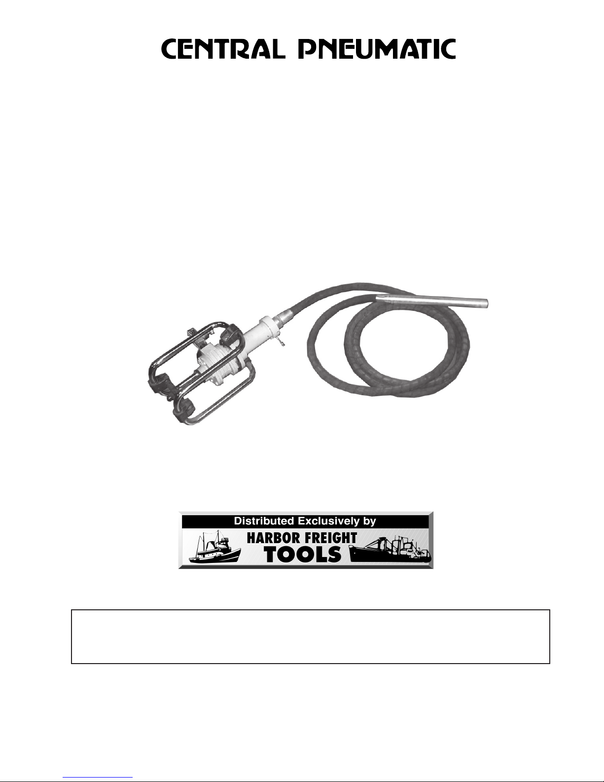
AIR CONCRETE VIBRATOR
Model 92804
ASSEMBLY and OPERATING
INSTRUCTIONS
3491 Mission Oaks Blvd., Camarillo, CA 93011
Visit our Web site at http://www.harborfreight.com
READ AND UNDERSTAND ALL WARNINGS
AND INSTRUCTIONS BEFORE USE.
Copyright© 2005 by Harbor Freight Tools®. All rights reserved. No portion of
this manual or any artwork contained herein may be reproduced in any shape or
form without the express written consent of Harbor Freight Tools.
For technical questions and replacement parts, please call 1-800-444-3353.
TO PREVENT SERIOUS INJURY,
Page 2

Specifications
Motor 3.6 HP, 3000 RPM (Free Speed 7900 RPM)
Maximum Air Pressure 90 PSI
Air Consumption 120 CFM @ 90 PSI
Starting T orque 5.3 FT/LBS
Stall Torque 8.7 FT/LBS
Air Inlet 1/2” - 14 NPT
Base Dimensions 19-1/4” L x 8-1/4” W x 9-3/4” H
Weight 46.25 LBS
Save This Manual
You will need the manual for the safety warnings and precautions, assembly instructions,
operating and maintenance procedures, parts list and diagram. Keep your invoice with this
manual. Write the invoice number on the inside of the front cover. Keep the manual and
invoice in a safe and dry place for future reference.
Safety Warnings and Precautions
WARNING: When using tool, basic safety precautions should always be followed to
reduce the risk of personal injury and damage to equipment.
Read all instructions before using this tool!
1. Keep work area clean. Cluttered areas invite injuries.
2. Observe work area conditions. Do not use machines or tools in damp or wet
locations. Don’t expose to rain. Keep work area well lit. Do not use electrically
powered compressors in the presence of flammable gases or liquids.
3. Keep children away. Children must never be allowed in the work area. Do not let
them handle machines, tools, extension cords, or air hoses.
4. Store idle equipment. When not in use, tools must be stored in a dry location to
inhibit rust. Always lock up tools and keep out of reach of children.
5. Use the right tool for the job. Do not attempt to force a small tool or attachment to
do the work of a larger industrial tool. There are certain applications for which this
tool was designed. It will do the job better and more safely at the rate for which it was
intended. Do not modify this tool and do not use this tool for a purpose for which it
was not intended.
6. Dress properly. Do not wear loose clothing or jewelry as they can be caught in
moving parts. Protective, electrically nonconductive clothes (including long pants) and
nonskid protective footwear are recommended when working. Wear restrictive hair
covering to contain long hair.
7. Use eye and ear protection. Always wear ANSI approved impact safety goggles and
noise dampening devices (i.e. earmuffs, ear plugs). Wear heavy work gloves.
8. Do not overreach. Keep proper footing and balance at all times. Do not reach over or
across running machines or air hoses.
Page 2SKU 92804 For technical questions, please call 1-800-444-3353
Page 3

9. Maintain tools with care. Keep tools clean for better and safer performance. Follow
instructions for lubricating and changing accessories. Inspect tool cords and air hoses
periodically and, if damaged, have them repaired by an authorized technician. The
handle must be kept clean, dry, and free from oil and grease at all times.
10. Disconnect air supply. Disconnect air hose when not in use.
11. Remove adjusting keys and wrenches. Check that keys and adjusting wrenches
are removed from the tool or machine work surface before plugging it in.
12. Avoid unintentional starting. Be sure the regulator is in the Off position when not in
use and before plugging in.
13. Stay alert. Watch what you are doing, use common sense. Do not operate any tool
when you are tired.
14. Check for damaged parts. Before using any tool, any part that appears damaged
should be carefully checked to determine that it will operate properly and perform its
intended function. Check for alignment and binding of moving parts; any broken parts
or mounting fixtures; and any other condition that may affect proper operation. Any
part that is damaged should be proper ly repaired or replaced by a qualified
technician. Do not use the tool if regulator does not operate properly.
15. Replacement parts and accessories. When servicing, use only identical
replacement parts. Use of any other parts will void the warranty. Only use accessories
intended for use with this tool.
16. Do not operate tool if under the influence of alcohol or drugs. Read warning
labels if taking prescription medicine to determine if your judgement or reflexes are
impaired while taking drugs. If there is any doubt, do not operate the tool.
17. Use proper size and type extension cord. If an extension cord is required for the air
compressor, it must be of the proper size and type to supply the correct current to the
compressor without heating up. Otherwise, the extension cord could melt and catch
fire, or cause electrical damage to the compressor. Check your air compressor’s
manual for the appropriate size cord.
18. Maintenance. For your safety, maintenance should be performed regularly by a
qualified technician.
19. Compressed air only. Never use combustible gas as a power source.
20. WARNING: Some dust created by power sanding, sawing, grinding, drilling, and other
construction activities, contains chemicals kno wn [to the State of California] to cause
cancer, birth defects or other reproductive harm. Some examples of these chemicals
are:
- Lead from lead-based paints
- Crystalline silica from bricks and cement or other masonry products
- Arsenic and chromium from chemicall y treated lumber
Your risk from these exposures varies, depending on how often y ou do this type of
work. To reduce your exposure to these chemicals: work in a well ventilated area, and
work with approved safety equipment, such as those dust masks that are specially
designed to filter out microscopic particles.
(California Health & Safety Code § 25249.5,
et seq.
)
Page 3SKU 92804 For technical questions, please call 1-800-444-3353
Page 4

21. This item creates powerful vibrations in both the workpiece and in the
operator’s body. Prolonged use could lead to personal injury.
22. Only use the Concrete Vibrator to vibrate and smooth wet concrete. Do not use
it on hard surfaces or you will damage the unit or cause personal injury.
Note: Performance of the compressor (if powered by line voltage) may vary depending on
variations in local line voltage. Extension cord usage may also affect tool performance.
Warning: The warnings, cautions, and instructions discussed in this instruction manual
cannot cover all possible conditions and situations that may occur. It must be understood by the operator that common sense and caution are factors which cannot be
built into this product, but must be supplied by the operator.
Unpacking
When unpacking, check to mak e sure that the product is intact and undamaged. If an y
parts are missing or broken, please call Harbor Freight Tools at the number on the cover of
this manual as soon as possible.
Connecting the Air Supply
Concrete
Vibrator
For best service you should incorporate an oiler, regulator, and inline filter, as shown in the
diagram above. Hoses, couplers, oilers, regulators, and filters are all available at Harbor
Freight Tools.
1. You will need to prepare an air connector (not included) to connect to the Air Inlet on
the Regulator (21), on the Concrete Vibrator. First, wrap the air connector with pipe
thread seal tape before threading it into the Air Inlet (see FIGURE 2 on page 5) on the
Regulator (21). Connect the air source hose to a quick connect coupler, and then to
the Concrete Vibr ator . The air source hose m ust be a sufficient size to provide enough
air volume to operate this tool.
Note: If y ou are not using an automatic oiler system, before operation, add a fe w drops
of Pneumatic Tool Oil to the airline connection. Add a fe w drops more after each hour
of continual use.
2 . Set the air pressure on the regulator to 90 PSI. Do not exceed the recommended air
pressure of 90 PSI.
3. Check the air connection for leaks. Disconnect from the air source.
Page 4SKU 92804 For technical questions, please call 1-800-444-3353
Page 5

Operation
WARNING! This Concrete Vibrator produces significant torque and vibration.
The elderly, infirm, and pregnant women should not use this device.
W ARNING! THE BASE UNIT OF THE CONCRETE VIBRA T OR MUST BE SECUREL Y
STRAPPED DOWN BEFORE USE.
Refer to cover photo and the assembly diagrams.
WARNING: Only use the Concrete Vibrator to vibrate and smooth wet concrete. Do
not use it on hard surfaces or you will damage the unit or cause personal injury.
Connecting the Vibrating Head to the Base Unit
1. Insert the Rod on the center of the Cylindrical Connector (A16) into the center hole in
the end of the Base Unit. Align the notches on the bottom of the Cylindrical Connector
(A16) with the handle on the Base Unit. Tur n the Handle to lock the Cylindrical Con-
nector (A16) into place. See FIGURE 1.
FIGURE 1
Cylindrical Connector (A16)
Rod
Base Unit
Notches
Operating the Unit
Handle
2. After making sure the Base Unit is strapped securely in place using the metal
Support Bracket (20) surrounding it, attach the air hose source and turn on the air
compressor. We recommend having a second person to adjust the Regulator (21) for
power. DO NOT LET GO OF THE CONCRETE VIBRATOR TUBE HEAD WHEN THE
UNIT IS ON. To adjust the Regulator (21), loosen the Lock Nut and adjust the air flow
using the Knob. After achieving the correct air flow, use a wrench to gently tighten the
lock nut. See FIGURE 2.
FIGURE 2
Support Bracket (20) of
Base Unit
Regulator (21)
Knob
Lock Nut
Air Inlet
Page 5SKU 92804 For technical questions, please call 1-800-444-3353
Page 6

Operation (continued)
Note: Grip the Vibrating Tube Head just above where the Flex Tube (A13) connects with the
Casing (A4).
3. If necessary , shake the Vibrator head to start the vibration. K eeping 3/4 of the Vibrating
Head inside the concrete, slowly mov e it within the area you desire to settle. Do not pull
the Vibrating Head out of the wet concrete with the unit on or wet concrete will vibrate
off the head covering the operator and the surrounding area. When you are finished,
have your partner turn off the air compressor and disconnect the air supply.
4. Loosening the Handle on the Base Unit (see FIGURE 1), remove the Vibrating Head
from the Base Unit.
5. Clean the concrete off of the unit and surrounding area before it dries.
Maintenance
Warning! Disconnect the Concrete Vibrator from the air source hose before attempting
any maintenance.
1. Clean the Vibrating Head immediately after each use, before any concrete dries on it.
Do not submerge the Base unit in water . Use a wet cloth to remove concrete from the
Vibrating Head. Do not use any harsh detergents or solvents to clean the Concrete
Vibrator .
2. Dry the Base Unit with a lint free cloth.
Page 6SKU 92804 For technical questions, please call 1-800-444-3353
Page 7

Motor Parts List
Part No. Description Qty.
1 Cylinder 1
2 Front End Plate 1
3 Rear End Plate 1
4 Rotor 1
4A Drive Key 1
5 Vane 4
6* Vane Spring 2
7* Vane Pin 4
8 Front Rotor Bearing 1
9 Rear Rotor Bearing 1
10 Rotor Shaft Seal 1
11 End Plate Gasket 2
12 Front End Cap 1
12A Front/Rear End Cap Screw 6
13 Front End Cap Seal 1
14 Rear End Cap 1
15 Rear End Cap Gasket 1
16 Muffler 1
17 Front/Rear End Plate Screw 12
18* Mounting Foot 4
19* Mounting Flange 4
20* Support Bracket 1
21* Regulator 1
* Not shown on the diagram.
Motor Assembly Diagram
NOTE: Some par ts are listed and shown for illustration purposes only and are not available
individually as replacement parts.
Page 7SKU 92804 For technical questions, please call 1-800-444-3353
Page 8

Vibrating Head Parts List
Part No. Description
A1 Cone
A2 Spacer
A3 Raceway
A4 Casing
A5 Rolling Body
A6 Oil Seal Ring
A7 Oil Seal Housing
A8 Oil Seal
A9 Bearing
A10 Pipe Adapter
A11 Shaft Adapter
A12 Flexible Shaft
A13 Flexible Pipe
A14 Cylindrical Plug
A15 Conical Sleeve
A16 Cylindrical Connector
Vibrating Head Assembly Diagram
THE MANUF ACTURER AND/OR DISTRIBUT OR HAS PRO VIDED THE PARTS DIA GRAM IN THIS
MANUAL AS A REFERENCE TOOL ONLY. NEITHER THE MANUFACTURER NOR DISTRIBUTOR MAKES ANY REPRESENTA TION OR W ARRANTY OF ANY KIND T O THE B UYER THAT HE
OR SHE IS QUALIFIED TO MAKE ANY REPAIRS TO THE PRODUCT OR THAT HE OR SHE IS
QUALIFIED TO REPLACE ANY PARTS OF THE PRODUCT. IN FACT, THE MANUFACTURER
AND/OR DISTRIBUTOR EXPRESSLY ST A TES T HA T ALL REP AIRS AND PARTS REPLACEMENTS
SHOULD BE UNDERTAKEN BY CERTIFIED AND LICENSED TECHNICIANS AND NO T BY THE
BUYER. THE BUYER ASSUMES ALL RISK AND LIABILITY ARISING OUT OF HIS OR HER
REPAIRS TO THE ORIGINAL PRODUCT OR REPLACEMENT PA RTS THERET O , OR ARISING
OUT OF HIS OR HER INSTALLATION OF REPLACEMENT PARTS THERETO.
PLEASE READ THE FOLLOWING CAREFULLY
Page 8SKU 92804 For technical questions, please call 1-800-444-3353
 Loading...