

Page 1
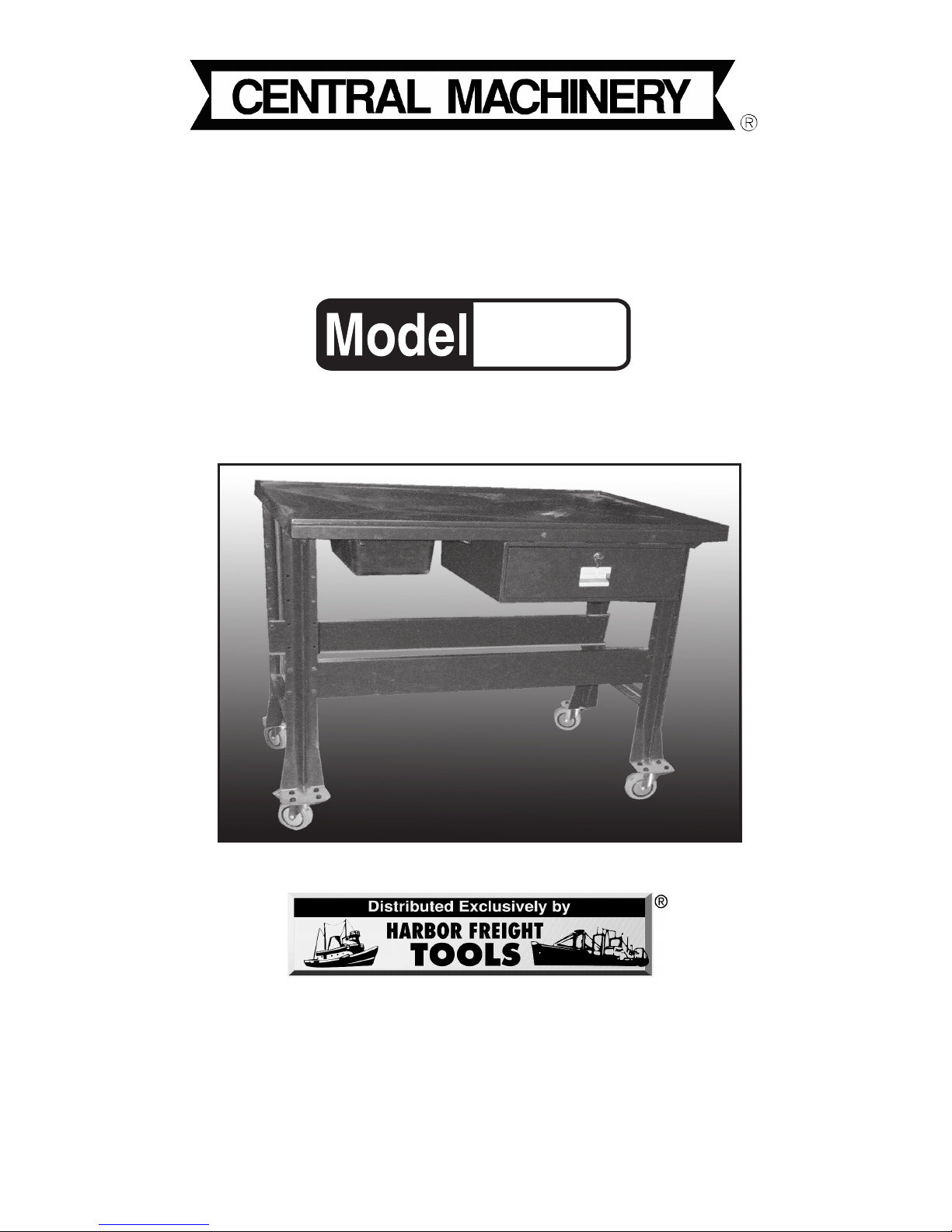
TRANSMISSION
TABLE
ASSEMBLY AND OPERATING INSTRUCTIONS
3491 Mission Oaks Blvd., Camarillo, CA 93011
Visit our Web site at http://www.harborfreight.com
Copyright © 2004 by Harbor Freight Tools®. All rights reser ved. No por tion of this
manual or any artwork contained herein may be reproduced in any shape or for m
without the express written consent of Harbor F reight T ools .
For technical questions and replacement parts, please call 1-800-444-3353
92409
Page 2

SKU 92409 For technical questions, please call: 1-800-444-335 Page 2
Specifications
Save This Manual
You will need the manual for the safety warnings and precautions, assembly
instructions, operating and maintenance procedures, parts list and diagram. K eep
your inv oice with this man ual. Write the inv oice number on the inside of the front
cover. Keep the manual and inv oice in a safe and dry place for future reference.
Safety Warnings and Precautions
WARNING: When using product, basic safety precautions should always be
followed to reduce the risk of personal injury and damage to equipment.
Read all instructions before using this product!
1. Keep work area c lean . Cluttered areas invite injuries.
2. Observe work area conditions. Do not use machines or po wer tools in
damp or wet locations. Don’t expose to rain. Keep work area well lighted.
3. Keep children away. Children must never be allowed in the work area. Do
not let them handle machines, tools, or extension cords. Do not allow
children to climb on or play on the Transmission Table.
4. When assembling, more than one person is needed for stabilizing par ts
being assembled and for lifting Table to an upright position.
5. Use the right product for the job. There are certain applications for which
this product was designed. Do not modify this product and do not use this
product for a purpose for which it was not intended.
6. Dress properly. Do not wear loose clothing or jew elry as they can be caught
in moving parts.
7. Use eye protection. Always wear ANSI approved impact safety goggles
when assembling this product, and when working with tools and equipment.
Overall Dimensions
Finish
Materials
Weight Capacity
Plastic Drain Tub Capacity
48-1/2” L x 31-1/2” W x 41” Tall
Powder Coated, Rust Resistant-Color Red
Stamped and Formed Sheet Steel Frame-Hard Rubber Casters (4)
880 Lbs.-Evenly Disributed
Holds 2.2 Gallons– 16-1/2” L x 10-3/4” W x 5-3/4” D
Transmission Repair Station has Table Top with Built-in Liquid Drainage Holes.
Page 3

SKU 92409 For technical questions, please call: 1-800-444-335 Page 3
8. Check for damaged par ts. Before using this table, any component that
appears damaged should be carefully checked to determine that it will not
effect the intended function of this product. Replace any broken parts or any
other condition that may affect proper operation. Any part that is damaged
should be properly repaired or replaced by a qualified technician.
9. Replacement parts and accessories. When servicing, use only identical
replacement parts. Use of any other parts will void the warranty.
10. If Keys to the Drawer of the Transmission Table are lost, Harbor Freight
Tools is not responsible. Contact a locksmith for replacement.
11. Place Transmission Table on a flat, level surface. When positioned
correctly, press the Lever on the Swivel Caster w/Locks to prevent
movement. Do not move the Transmission Table while loaded with objects.
12. When working with flammable products like grease, oil, antifreeze,
gasoline, etc., avoid placing table in an area with a pilot light such as in a
waterheater. Be sure the area is well ventilated to avoid a fire.
13. Dispose all hazardous waste products properly. Do not dispose
products in a sewer, stream or ocean. Check with your city government
center for a Hazardous Waste Disposal Plant near you.
14. Once the Transmission Table is Located in it’s desired location, always
lock the Swivel Caster Wheels, that have locks, to prevent unintentional
rolling of the Table.
Warning: The warnings, cautions, and instructions discussed in this instruction manual cannot cover all possible conditions and situations that may occur . It must be understood by the operator that common sense and caution are
factors which cannot be built into this product, but must be supplied by the
operator.
Unpacking
When unpacking, check to make sure all parts are included. See the parts lists on
Page 7. If any parts are missing or broken, please call Harbor Freight Tools at the
number on the cover of this manual.
Page 4

SKU 92409 For technical questions, please call: 1-800-444-335 Page 4
3. Attach the Frame for the Drawer (7) to the underside of the Table Top (6). Be
sure you are installing the Frame (7) in the correct position. Note: The
predrilled holes for the Frame are closer to the front of the Table Top (6).
This will insure the Drawer (8) will be stable. Use Bolts (3), Washers (5), and
Nuts (4). Tighten all hardware.
Refer to the Assembly Drawing on Page 7.
Assembly
1. To protect the finish, set the Table Top (6), face down, on a smooth surface on
the floor. Bolt the Legs (2) into place using Bolts (3), Washers (5), and
Nuts (4).
See Figure 1.
2. Place the Support Braces (11) so that they line up with the predrilled holes
and secure the Support Braces (11) with Bolts (3), Washers (5), and Nuts (4).
See Figure 1.
Figure 1
Leg (2)
Support Braces (11)
Bolts (3)
Washer (5)
Nut (4)
Figure 2
4. Attach the Metal Drawer (8) to the underside of the Table Top (6) where you
have installed the Frame (7). (Note: You need to have the Drawer “out” of
the assembly to install it). Use Bolts (3) in six places. Tighten.
Refer to the
Assembly Drawing on Page 7 and Figure 2.
5. Line the Drawer (8) up with the track in the Metal Drawer assembly (8) by
tilting the front end of the Drawer down, then lifting up the Drawer and sliding
it into place. If it does not fit properly, repeat until you have it on track.
See Figure 3.
Metal Drawer (8)
With Drawer
Removed
Drawer (8) at a Tilt
Figure 3
Track
Page 5

SKU 92409 For technical questions, please call: 1-800-444-335 Page 5
Installing the Plastic Tub
1. There are two rails that act as tracks for the
Plastic Tub (9). These rails are installed under
the drainage holes at one end of the
Transmission Table Top (6).
See Figures 6 & 8.
2. Slide the Plastic Tub (9) into the track on the
underside of the Table Top (6). Be sure it is
positioned under the drain holes before
working on machinery to insure catching any
liquids.
See Figures 6 & 8.
3. After sliding the Plastic Tub (9) into place,
screw in the two Bolts (12) into the holes on
the track. This will prevent the Plastic Tub from
sliding too far forward. Remove the Bolts to
empty fluids caught in the Tub.
Follow the
disposal of Hazardous Waste instruction on
Page 3. See Figure 7.
Plastic
Tub (9)
Figure 6
Figure 7
Bolt 12
Track
Plastic
Tub (9)
Figure 4
Figure 5
Key and
Lock (13)
Plastic
Drawer
Stop
7. Use the Keys and Lock (13) to secure objects
when not in use.
Figure 5.
6. Once the Drawer (8) is in place on the track,
install the Locks (13) at the back of the Drawer.
Push the Button on each side into the predrilled
holes to secure Drawer (8). This will prevent the
Drawer from being pulled out too far and
spilling the contents on the floor. To remove the
Drawer, reverse the step.
See Figure 4.
Figure 8
Drainage
Holes
Page 6

SKU 92409 For technical questions, please call: 1-800-444-335 Page 6
Installing the Casters
1. Attach two Swivel Casters (1) on one side of
the Table Legs (2), using Bolts (3), Washers
(5), and Nuts (4). Attach the two Swivel
Castors with Locks (10) to the opposite Legs
(2), using Bolts (3), Washers (5), and Nuts (4).
(Note: To lock and unlock, use your foot to
press or release lever).
2. Once assembly is complete, set the
Transmission Table upright. Roll the Table and
check that it is assembled correctly. Check that
the Transmission Table is level. Tighten all
hardware. Caution: At all times, the Table Top
should be emptied of any load that is on top
before moving. Lock the Swivel Casters (1)
and distribute the weight evenly when working
on any machinery.
See Figures 9 & 10.
Bolt (3)
Washer (5)
Nut (4)
Figure 10
Lock
Lever
Swivel Lock
Caster (10)
Lever
Swivel
Castor with
Lock (10)
Maintenence
1. To remove dust, use a damp cloth. To remove grease or oil, use a detergent
based cleaning solvent, rinse with damp cloth, and dry.
2. This product should be assembled and stored in a dry area.
Figure 9
Note: Never exceed the maximum load capacity as described on page 2.
Page 7

SKU 92409 For technical questions, please call: 1-800-444-335 Page 7
PLEASE READ THE FOLLOWING CAREFULLY
THE MANUF ACTURER AND/OR DISTRIB UTOR HAS PR O VIDED THE PARTS DIAGRAM IN
THIS MANUAL AS A REFERENCE TOOL ONLY. NEITHER THE MANUFACTURER NOR
DISTRIBUTOR MAKES ANY REPRESENTATION OR WARRANTY OF ANY KIND TO THE
BUYER THAT HE OR SHE IS QUALIFIED TO MAKE ANY REPAIRS TO THE PRODUCT OR
THAT HE OR SHE IS QUALIFIED TO REPLACE ANY PARTS OF THE PR ODUCT. IN FACT,
THE MANUFACTURER AND/OR DISTRIBUTOR EXPRESSLY STATES THat ALL REPAIRS
AND P AR TS REPLACEMENTS SHOULD BE UNDER T AKEN BY CER TIFIED AND LICENSED
TECHNICIANS AND NOT BY THE B UYER. THE BUYER ASSUMES ALL RISK AND LIABILITY
ARISING OUT OF HIS OR HER REP AIRS TO THE ORIGINAL PRODUCT OR REPLA CEMENT
PARTS THERET O , OR ARISING OUT OF HIS OR HER INSTALLA TION OF REPLACEMENT
P ARTS THERET O.
Parts List
Part # Description Qty.
2
2
48
44
44
1
1
1
1
2
2
2
1
Swivel Caster
Leg
Bolt (M8 x 15)
Nut (M8)
Washer
Top of Table
Frame for the Drawer
Metal Drawer (Assmebly)
Plastic Tub
Swivel Caster with Lock
Support Brace
Bolt (M8 x 30)
Lock and Keys Set
1
2
3
4
5
6
7
8
9
10
11
12
13
Part 1
Part 2
Part 4
Part 3
Part 5
Assembly Drawing
Part 6
Part 7
Part 8
Part 9
Part 10
Part 11
Part 12
Part 13
NOTE: Some parts are listed and shown for illustration purposes only and are not available
individually as replacement parts.
 Loading...