

Page 1

COMPOUND MITER SACOMPOUND MITER SA
COMPOUND MITER SA
COMPOUND MITER SACOMPOUND MITER SA
10 INCH10 INCH
10 INCH
10 INCH10 INCH
WW
W
WW
90597
ASSEMBLY AND OPERATING INSTRUCTIONS
3491 MISSION OAKS BLVD., CAMARILLO, CA 93011
VISIT OUR WEB SITE AT HTTP://WWW.HARBORFREIGHT.COM
Copyright © 2003 by Harbor Freight Tools®. All r ights reserved. No portion of
this manual or any artwork contained herein may be reproduced in any shape
or form without the express written consent of Harbor Freight Tools.
For technical questions and replacement parts, please call 1-800-444-3353
Page 2
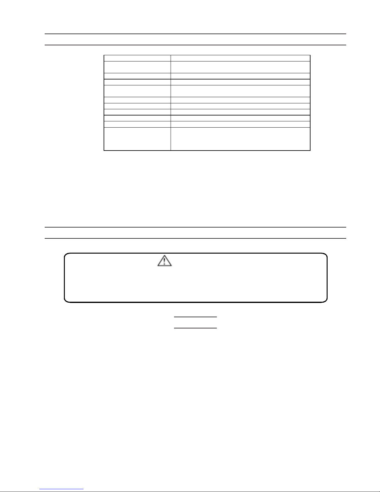
SPECIFICATIONS
Power R equirem ent 115 VAC , 60 Hz, 13 amps (no load: 7.4 amps
Motor 5200 RP M , 3 HP, 1495 W atts
Table Dimensions 19-1/2 x 7-1/4 inches; 10 in ch (dia.) turnta ble
Table Stops Positive Stops: 0, 15, 22.5 degrees;
Overall Dimensions 21-3/4 x 21-3/8 x 20 inches
Saw Blade 10 inch, 60 tooth, 1 inch arbor
Blade Height 4-1/2 inches (maximum)
Power C ord 6-1/2 feet; Polarized plug
Weight 32.9 lbs.
Features Trigger switch w ith safety button
Item Description
with blade); Startup am ps: 27.4 am ps
Miter Bevel: 30 and 45 degrees L/R
Electric brake
Spring retracted head assy.
Retractable Blade Cover
SA VE THIS MANUAL
You will need the manual for the safety warnings and precautions, assembly instructions,
operating and maintenance procedures, parts list and diagram. Keep your invoice with this
manual. Write the invoice number on the inside of the front cover. Keep the manual and
invoice in a safe and dry place for future reference.
GENERAL SAFETY RULES
WARNING!
READ AND UNDERSTA ND ALL INSTRUCTIONS. Failure to follow all instructions listed belo w may result in electric shock, fire, and/or serious injury .
SAVE THESE INSTRUCTIONS
Work Area
1. Keep your work area clean and well lit. Cluttered benches and dark areas invite
accidents.
2. Do not operate power tools in explosive atmospheres, such as in the presence
of flammable liquids, gases, or dust. Power tools create sparks which may ignite
the dust or fumes.
3. Keep bystanders, children, and visitors away while operating a power tool.
Distractions can cause you to lose control. Protect others in the work area from
debris such as chips and sparks. Provide barriers or shields as needed.
4. Maintain a safe working environment. Keep the wor k area well lit. Make sure there
is adequate surrounding workspace. Always keep the work area free of obstructions,
grease, oil, trash, and other debris. Do not use a power tool in areas near flammable
chemicals, dusts, and vapors. Do not use this product in a damp or wet location.
Page 2SKU 90597
REV 12/03
Page 3

Electrical Safety
5. Avoid body contact with grounded surfaces such as pipes, radiators, ranges,
and refrigerators. There is an increased risk of electric shock if your body is
grounded.
6. Do not expose power tools to rain or wet conditions. Water entering a power tool
will increase the risk of electric shock.
7. Grounded tools must be plugged into an outlet properly installed and grounded
in accordance with all codes and ordinances. Never remove the grounding
prong or modify the plug in any way. Do not use any adapter plugs. Check with
a qualified electrician if you are in doubt as to whether the outlet is properly
grounded. If the tools should electrically malfunction or break down, grounding
provides a low resistance path to carry electricity away from the user.
8. Double insulated tools are equipped with a polarized plug (one blade is wider
than the other). This plug will fit in a polarized outlet only one way. If the plug
does not fit fully in the outlet, reverse the plug. If it still does not fit, contact a
qualified electrician to install a polarized outlet. Do not change the plug in any
way. Double insulation
cord and grounded power supply system.
9. Do not abuse the Power Cord. Never use the Power Cord to carry the tools or
pull the Plug from an outlet. Keep the Power Cord away from heat, oil, sharp
edges, or moving parts. Replace damaged Power Cords immediately. Damaged
Power Cords increase the r isk of electr ic shock.
10. When operating a power tool outside, use an outdoor extension cord marked
“W-A” or “W”. These extension cords are rated for outdoor use, and reduce the risk
of electric shock.
eliminates the need for the three wire grounded power
Personal Safety
11. Stay alert. Watch what you are doing, and use common sense when operating a
power tool. Do not use a power tool while tired or under the influence of drugs,
alcohol, or medication. A moment of inattention while operating power tools may
result in serious personal injury.
12. Dress properly. Do not wear loose clothing or jewelry. Contain long hair. Keep
your hair, clothing, and gloves away from moving parts. Loose clothes, jewelry, or
long hair can be caught in moving parts.
13. Avoid accidental starting. Be sure the P o wer Switc h is off before plugging in.
Carrying power tools with your finger on the Power Switch, or plugging in power tools
with the Power Switch on, invites accidents.
14. Remove adjusting keys or wrenches before turning the power tool on. A wrench
or a key that is left attached to a rotating part of the power tool may result in personal
injury.
Page 3SKU 90597
Page 4

15. Do not overreach. Keep proper footing and balance at all times. Proper footing
and balance enables better control of the power tool in unexpected situations.
16. Use safety equipment. Always wear eye protection. Dust mask, nonskid safety
shoes, hard hat, or hearing protection must be used for appropriate conditions.
17. WARNING! Some dust created by power sanding, sawing, grinding, drilling, and
other construction activities, contain chemicals known (to the State of California) to
cause cancer, birth defects or other reproductive harm. Some examples of these
chemicals are: lead from lead-based paints, cr ystalline silica from bricks and cement
or other masonry products, arsenic and chromium from chemically treated lumber.
Your risk from these exposures var ies, depending on how often you do this type of
work. To reduce your exposure to these chemicals: work in a well ventilated area, and
work with approved safety equipment, such as those dust masks that are specially
designed to filter out microscopic particles.
(California Health & Safety Code 25249.5,
et seq.)
18. WARNING! People with pacemakers should consult their physician(s) before
using this product. Operation of electr ical equipment in close proximity to a heart
pacemaker could cause interference or failure of the pacemaker.
Tool Use and Care
19. Use clamps or other practical ways to secure and support the workpiece to a
stable platform. Holding the work by hand or against your body is unstable and may
lead to loss of control.
20. Do not force the tool. Use the correct tool for your application. The correct tool
will do the job better and safer at the rate for which it is designed.
21. Do not use the power tool if the Power Switch does not turn it on or off. Any tool
that cannot be controlled with the Power Switch is dangerous and must be replaced.
22. Disconnect the Power Cord Plug from the power source before making any
adjustments, changing accessories, or storing the tool. Such preventive safety
measures reduce the risk of starting the tool accidentally.
23. Store idle tools out of reach of children and other untrained persons. Tools are
dangerous in the hands of untrained users.
24. Maintain tools with care. Keep cutting tools sharp and c lean. Properly
maintained tools with a sharp cutting edge are less likely to bind and are easier to
control. Do not use a damaged tool. Tag damaged tools “Do not use” until repaired.
25. Check for misalignment or binding of moving parts, breakage of parts, and any
other condition that may affect the tool’s operation. If damaged, have the tool
serviced before using. Many accidents are caused by poorly maintained tools.
26. Use only accessories that are recommended by the manufacturer for your
model. Accessories that may be suitable for one tool may become hazardous when
used on another tool.
Page 4SKU 90597
Page 5

27. Maintain labels and nameplates on the Compound Miter Saw. These carry
important information. If unreadable or missing, contact Harbor Freight Tools for a
replacement.
Service
28. Tool service must be performed only by qualified repair personnel. Service or
maintenance performed by unqualified personnel could result in a risk of injury.
29. When servicing a tool, use only identical replacement parts. Follow
instructions in the
“Inspection, Maintenance, And Cleaning”
section of this
manual. Use of unauthorized parts or failure to follow maintenance instructions may
create a risk of electric shock or injury.
SPECIFIC SAFETY RULES FOR THIS PRODUCT
1 Always wear safety impact eye goggles and heavy work gloves when using the
Compound Miter Saw. Using personal safety devices reduce the risk for injury. Safety
impact eye goggles and heavy work gloves are available from Harbor Freight Tools.
2 Avoid unintentional starting. Make sure you are prepared to begin work before turning
on the Compound Miter Saw.
3 Do not force the Compound Miter Saw. This tool will do the work better and safer at
the speed and capacity for which it was designed.
4 Always unplug the Compound Miter Saw from its electrical outlet before performing
and inspection, maintenance, or cleaning procedures.
5 Never leave the Compound Miter Saw unattended while running. Turn power off if you
have to leave the area.
6 Before each use, check all nuts, bolts, and screws for tightness. Vibration during
mixing may cause these to loosen.
7 Keep extension cord off the ground and away from water.
8 Always connect the Line Cord to a Ground Fault Circuit Interrupter (GFCI) protected
electrical outlet.
9 Do not disable blade guard. Do not saw without a proper operating blade guard in
place.
10 Examine blade before using. Before each use, examine blade for chips, cracks, or
(1)
other damage. Do not use if damaged.
11 Do not use without first mounting saw to a workbench.
12 Check for tightness on all saw adjustments before using.
13. Keep hands away from moving saw blade. If the workpiece to be cut is less than 4
inches long, do not hold with your hand, use a clamp. Do not remove jammed or
cutoff pieces until the saw blade has stopped and the Line Cord is unplugged.
Page 5SKU 90597
Page 6

14. Cut only the proper type of material. Never cut ferrous metals or masonry. The
abrasive particles generated will damage the saw..
15. Protect the electrical supply line with at least a 15 ampere time-delay fuse or circuit
breaker.
16. Make certain the blade rotates in the correct direction, with the teeth at the bottom of
the blade pointing to the rear of the Miter Saw.
17. Be sure that all clamp handles are tight before starting any operation.
18. Check that all blade and clamp washers are clean and recessed sides of collars are
against the blade. Tighten arbor screw securely.
19. Keep saw blade sharp and properly set.
20. Keep motor air slots free of chips and dirt.
21. Use blade guards at all times.
22. Suppor t long stock with an outboard tool rest (not included).
23. Do not use blades that are smaller or larger than 10 inches, and rated less than 5200
RPM.
24. Do not wedge anything against fan to hold motor shaft.
25. Do not force the cutting action; stalling of the motor can cause major damage. Allow
motor to reach full speed before cutting.
26. Do not allow anyone to stand behind the saw during operation.
27. Do not apply lubricants to the blade while it is running.
28. Never place hands in the saw area (around, behind, or underside) while the unit is
running, or when only connected to the power source. Always unplug unit before
handling.
29. Do not perform any action freehand.
30. Do not move either hand from the saw or workpiece, or raise the arm until the blade
has stopped.
31. Do not use without the kerf plate, or when kerf slot is wider than 3/8 inch.
32. Removal of the material clamp is necessary if an angled cut would interfer with the
clamp.
Page 6SKU 90597
REV 12/03
Page 7

GROUNDING
WARNING!
Improperly connecting the grounding wire can result in the risk of electric
shock. Check with a qualfified electrician if you are in doubt as to whether the
outlet is properly grounded. Do not modify the power cord plug provided with
the tool. Ne ver remove the grounding pr ong from the plug. Do not use the tool if
the power cord or plug is damaged. If damaged, have it repaired by a service
facility before us e. If the plug will not fit the outlet, ha ve a proper outlet install ed
by a qualified electrician.
Grounded Tools: Tools with Three Prong Plugs
1. Tools marked with “Grounding Required” have a three wire cord and three prong
grounding plug. The plug must be connected to a properly grounded outlet. If the tool
should electrically malfunction or break down, grounding provides a low resistance
path to carry electricity away from the user, reducing the risk of electric shock. (See
Figure A.)
2. The grounding prong in the plug is connected through the green wire inside the cord
to the grounding system in the tool. The green wire in the cord must be the only wire
connected to the tool’s grounding system and must never be attached to an
electrically “live” terminal. (See Figure A.)
3. Your tool must be plugged into an appropriate outlet, properly installed and grounded
in accordance with all codes and ordinances. The plug and outlet should look like
those in the following illustration. (See Figure A.)
Figure A
Figure B
Double Insulated Tools: T ools with Tw o Prong Plugs
4. Tools marked “Double Insulated” do not require grounding. They have a special double
insulation system which satisfies OSHA requirements and complies with the
applicable standards of Underwriters Laboratories, Inc., the Canadian Standard
Association, and the National Electrical Code. (See Figure B above.)
5. Double insulated tools may be used in either of the 120 volt outlets shown in the
following illustration. (See Figure B above.)
Page 7SKU 90597
Page 8

EXTENSION CORDS
1.
Grounded tools
either a two or three wire extension cord.
2. As the distance from the supply outlet increases, you must use a heavier gauge
extension cord. Using extension cords with inadequately sized wire causes a serious
drop in voltage, resulting in loss of power and possible tool damage. (See T ab le A.)
3. The smaller the gauge number of the wire, the greater the capacity of the cord. For
example, a 14 gauge cord can carry a higher current than a 16 gauge cord. (See
Table A.)
4. When using more than one extension cord to make up the total length, make sure
each cord contains at least the minimum wire size required. (See Table A.)
5. If you are using one extension cord for more than one tool, add the nameplate
amperes and use the sum to determine the required minimum cord size. (See Table
A.)
6. If you are using an extension cord outdoors, make sure it is marked with the suffix “WA” (“W” in Canada) to indicate it is acceptable for outdoor use.
7. Make sure your extension cord is properly wired and in good electrical condition.
Always replace a damaged extension cord or have it repaired by a qualified electrician
before using it.
require a three wire extension cord.
Double Insulated
tools can use
8. Protect your extension cords from sharp objects, excessive heat, and damp or wet
areas.
Table A
RECOMM ENDED MINIMUM WIRE GAUGE FOR EXTENSION CORDS*
(120 VOLT)
NAMEPLATE
AMPERES
(At F u ll Lo a d )
25
Feet
0 – 2.0 18 18 18 18 16
2.1 – 3.4 18 18 18 16 14
3.5 – 5.0 18 18 16 14 12
5.1 – 7.0 18 16 14 12 12
7.1 – 12.0 18 14 12 10 -
12.1 – 16.0 14 12 10 - -
16.1 – 20.0 12 10 - - * Based on limiting the line voltage drop to five volts at 150% of the rated amperes.
EXTENSION CORD LENG TH
50
Feet
75
Feet
100
Feet
150
Feet
Page 8SKU 90597
Page 9

SYMBOLOGY
Table B
UNPACKING
When unpacking, check to mak e sure that all the parts are included. Refer to the Assembly
section, and the Assembly Drawing and Parts List at the end of this manual. The main parts
include the 10 inch Miter Saw, 10 inch 28-tooth Saw Blade, Blade Removal Hex Wrench,
Dust Collection Bag, and Material Clamp.
Figure C
Dust Collection Bag
10 inch 28-tooth Saw Blade
Material Clamp
10 inch Miter Saw
Blade Removal Hex
Wrench (not shown)
If any parts are missing or broken, please call Harbor Freight Tools at the number on the
cover of this manual as soon as possible.
(1)
Page 9SKU 90597
Page 10

ASSEMBLY INSTRUCTIONS
Bench Mounting
1. Place the saw on a sturdy bench able to support the weight of the saw and any
possible stock that will be cut.
2. Use the Miter Saw bench mounting holes in all four feet to mount to a bench using
hardware. Use 3/8” nuts and bolts (not supplied).
Optionally, to provide portability, the saw can be bolted to a piece of 1/2 inch plywood,
that can then be clamped (temporarily) to a solid bench.
Note: If the saw is mounted to a piece of plywood, make sure that the mounting screws do not
protrude from the bottom of the plywood base. The plywood must be true and not warped to
prevent binding and inaccurate cuts. The plywood must sit flush on the work suppor t. When
clamping, be sure that the clamps will not interfere with proper saw operation, or obstruct the
placement of stock to be cut.
Installing a New Saw Blade
1. Always use 10 inch saw blades with one inch arbor holes. The saw blade speed rating
must be at least 5200 RPM.
Refer to Table C for saw blade applications and types.
TABLE C
APPLICATION
Fine Trim Molding
Trim, Framing,
Pressure Treated
Decking
Aluminum
BLADE
DESCRIPTION
Precision Trim
Carbide
Combination,
multi-purpose
Non-ferrous metal
cutting
No. OF TEETH TYPE OF CUT
60 ~ 100
28 ~ 60
60 ~ 80 - - - -
Very smooth,
splinter free
Smooth, fast
cut
2. Unplug the Miter Saw Power Cord from the electrical outlet.
3. Press down on the Saw Arm, pull out the Lock Down Pin Knob (75), and raise the
Saw Arm to the upper position. Refer to Figures E and F on the next page.
4. Loosen (but do not remove) the Guard Plate Screw (67) until the Guard Plate (66) can
be raised enough to permit access to the Blade Screw (71).
5. Hold the Lower Guard up and press the Spindle Lock
Figure D
(17) button with one hand. See Figure D.
Rotate the Saw Blade until the Spindle Lock catches
and the blade stops.
(17)
Page 10SKU 90597
Page 11

6. Using the supplied Blade Hex Wrench in the other hand, loosen (clockwise) the lefthand threaded Blade Screw (71). Remove the Blade Screw, Washer (70), Outer
Flange (69), and then the Saw Blade.
7. Mount the saw blade over the Spindle (53) shaft.
The teeth at the bottom of the saw blade should be pointing toward the back of the saw
(away from operator).
8. Replace the Outer Flange and Washer over the Spindle, then insert the Blade Screw.
Still pressing in on the Spindle Lock, retighten the Blade Screw (counterclockwise)
using the Blade Hex Wrench.
9. Lower the Guard Plate (66) and hold down, then firmly tighten the Guard Plate Screw
(67). Failure to do so will cause serious damage to the saw.
CONTROLS AND INDICATORS
Figure E Figure F
Switch
(32)
Guard Plate Screw (67)
Guard Plate (66)
Lock Down Pin (75)
Material Clamp (126)
Angle Setting Lever (87)
Mounting Holes
Safety
Button (36)
Safety
Cover (62)
Miter Side
Handle (112)
Miter Scale
OPERATING INSTRUCTIONS
Guard Actuation and Visibility
The Blade Safety Cover on the Miter Saw has been designed to automatically raise when
the arm is brought down, and to lower over the saw blade when the arm is raised. This
Blade guard can be raised by hand when installing or removing saw blades, or for inspection of blade.
Warning: Never raise the Safety Cover manually unless the saw is turned off, the saw
blade has stopped turning, and the Line Cord in unplugged from the electrical circuit.
Page 11SKU 90597
Page 12

Basic Operation
1. Plug the Power Cord Plug into a 115 VAC, 60 Hz electrical outlet. Be sure the cord
does not interfere with the saw operation or workpiece.
2. Place the workpiece on the Base table and against the Fence.
If the workpiece is short in length, use the Material Clamp to hold it in place. Do not
hold with your hand.
3. Press in (and hold) the Safety Button (36), then squeeze the trigger Switch (32) to
turn the saw on. Release the Safety Button.
4. When the saw blade is turning at full speed, slowly bring down the Saw Arm to
complete the cut.
5. When the cut is complete, release the Switch and raise the Saw Arm to its upper
most position.
6. Wait until the Blade comes to a complete stop before removing the stock from the
Base table.
Making Crosscuts
A crosscut is made by cutting wood across the grain at any angle. Miter crosscuts are
made with the miter arm at some angle other than zero. This angle is often 45 degrees for
making corners, but can be set anywhere from zero to 45 degrees (left or right).
1. Loosen (counterclockwise) the Miter Side Handle (112) and press down on the
handle. Move it (left or right) to the desired angle.
There are locking stops at 0, 15, 22.5, 30, and 45 degrees.
2. Tighten the Miter Side Handle.
3. Align the wood stock on the table, and flush against the Fence Guide (97). Clamp
material in place.
4. Press in (and hold) the Safety Button, then squeeze the trigger Switch (32) to turn the
saw on. Release the Safety Button. Note: Removal of the Material Clamp (126) is
necessary if an angled cut would interfer with the clamp.
5. When the saw blade is turning at full speed, slowly bring down the Saw Arm to
complete the cut.
6. When the cut is complete, release the Switch and raise the Saw Arm to its upper
most position.
The smoothness of any cut depends on a number of variables. Things like the material
being cut, saw blade type and sharpness, and the rate of cut all contribute to the quality of
the cut.
Quality of Cut
Page 12SKU 90597
REV 12/03
Page 13

When the smoothest cuts are desired for molding and other precision work, use a sharp (60
tooth carbide) saw blade and a slo wer, even cutting r ate . To ensure that material does not
creep while cutting, clamp it securely in place. Always let the saw blade come to a full stop
before raising the arm.
If small fibers of wood still split out at the rear of the workpiece, stick a piece of masking tape
on the wood where the cut will be made. Saw through the tape and carefully remove tape
when finished.
Body and Hand Position
Proper positioning of your body and hands when operating the Miter Saw will make cutting
easier, more accurate, and safer. See Figures G.
Caution: Never place hands near the cutting area. Place hands no closer than six inches
from the saw blade. Never cross hands.
Figure G
• Hold the workpiece tightly to the table and the Fence when cutting.
• Keep hands in position until the trigger Switch has been released and the saw blade has
completely stopped.
• Always make dry runs (without power) before finish cuts so that you can check the path
of the saw blade.
• Keep both feet fir mly planted on the floor and maintain proper balance.
• As you move the miter arm left and right, follow it and stand slightly to the side of the saw
blade.
Page 13SKU 90597
Page 14

Clamping the Workpiece
Always clamp the workpiece to the saw Fence or Base when possible.
1. Unplug the saw P ower Line Cord from the electrical outlet.
2. Clamp the workpiece to either side of the saw blade against the flat surface of the
Fence or Base.
3. When cutting small pieces requiring your hand to be dangerously close (within 6”) to
the saw blade, a clamp must be used to prevent loss of control.
4. The Material Clamp (126) must be removed from the left side of the Saw Base (125)
when cutting 45 degree miters to the left.
Cutting Base Molding
1. Position the wood against the Fence and clamp it in place. See Figure H.
2. Squeeze the Trigger Handle to turn the saw on.
3. When the saw blade reaches full speed, lower the arm smoothly while making the cut.
Figure H
When mitering to the right side of a base molding wider than 3.9” (3-7/8”) standing vertically
against the Fence, the saw can only cut through the board up to 1 inch from the end of the
board. Trying to cut more than an inch will cause the saw’s gear case to interfere with the
workpiece.
If the cut must be made somewhere other than 1” from the end of the molding, cut off the
molding at 90 degrees, approximately 1” longer than your final length. Then make the miter
Page 14SKU 90597
REV 12/03
Page 15

cut as described above.
Special Cuts
Caution: Never make any cut without firmly clamping down the workpiece.
Aluminum Cutting -- Aluminum extrusions such as those used when making aluminum
screen and storm windows can easily be cut with the miter saw.
1. Position the workpiece so that you will be cutting the thinnest cross section. See
Figure J. Clamp the material to the Fence or Base.
2. Use a wax lubricant when cutting aluminum. Apply the stick wax directly to the
(stopped) saw blade before cutting. The wax provides proper lubrication and keeps
chips from adhering to the saw blade.
Figure J
Cutting Bowed Material
1. When cutting bowed material, always position it as shown in Figure K.
Positioning the material incorrectly will cause it to pinch the saw blade near the
completion of the cut. Clamp the mater ial to the Fence or Base.
Figure K
Page 15SKU 90597
Page 16

INSPECTION, MAINTENANCE, AND CLEANING
1. After use, blow table top and underneath, and motor holes clean with an air hose.
2. Empty Dust Collector Bag after each use.
Warning: Do not empty Dust Collection Bag around any sparks or flame. An explosion
could occur.
3. Periodically wipe down all metal parts with a clean cloth and a light oil.
Never use solvents to clean plastic par ts.
4. All motor bearings are factory lubricated and do not require maintenance.
5.
WARNING! Make sure the tool is unplugged from its electrical outlet before
performing any inspection, maintenance, or cleaning procedures.
6. Before each use, inspect the general condition of the Miter Saw. Check for loose
screws, misalignment or binding of moving parts, cracked or broken parts, damaged
electrical wiring, and any other condition that may affect its safe operation. If
abnormal noise or vibration occurs, have the problem corrected before fur ther use. Do
not use damaged equipment.
7. Periodically recheck all nuts, bolts, and screws for tightness.
PLEASE READ THE FOLLOWING CAREFULLY
THE MANUF ACTURER AND/OR DISTRIBUT OR HAS PRO VIDED THE PAR TS DIAGRAM IN THIS
MANUAL AS A REFERENCE TOOL ONLY. NEITHER THE MANUFACTURER NOR DISTRIBUTOR MAKES ANY REPRESENTATION OR W ARRANTY OF ANY KIND TO THE BUYER THA T HE
OR SHE IS QUALIFIED TO MAKE ANY REPAIRS TO THE PRODUCT OR THAT HE OR SHE IS
QUALIFIED TO REPLACE ANY PARTS OF THE PRODUCT. IN FACT, THE MANUFACTURER
AND/OR DISTRIBUTOR EXPRESSLY STATES THA T ALL REPAIRS AND PARTS REPLA CEMENTS
SHOULD BE UNDERTAKEN BY CERTIFIED AND LICENSED TECHNICIANS AND NO T BY THE
BUYER. THE BUYER ASSUMES ALL RISK AND LIABILITY ARISING OUT OF HIS OR HER
REPAIRS TO THE ORIGINAL PRODUCT OR REPLACEMENT PARTS THERETO, OR ARISING
OUT OF HIS OR HER INSTALLATION OF REPLACEMENT PARTS THERETO.
Page 16SKU 90597
Page 17

,
,
)
r
g
r
g
r
r
g
g
g
g
g
r
r
r
g
r
y
g
g
r
g
g
g
r
g
r
r
y
8. Store in a clean and dry location.
PARTS LIST
Replacing the Motor Carbon Brushes
It may become necessary at sometime to replace the motor brushes when the motor performance decreases, or stops working completely. This procedure should be done by a
qualified technician.
Using a screwdriver, remove the Brush Holder Cap (7) and Carbon Brush (6) from the
Motor Housing (3). Refer to the Assembly Drawing. If the brushes are wor n down more than
1/2, replace both brushes. It could be, however, that they just need cleaning with an ink
eraser.
Part # Description Qty. Part # Description Qty.
1. .
2.
3.
4.
5. Carbon Brush Holde
6. Carbon Brush 2 75. Knob, Lock Down Pin 1
7. Cap, Brush Holde
8.
9.
10.
11.
12.
13.
14.
15.
16.
17.
18.
19.
20.
21. Screw, Pan Head, M5x20 2 90. Screw, Hex., Socket No. Hd., M8x20 2
22. Screw, Pan Head, M4x23 4 91. Nut, Hex., M8 2
23. Cord Guard 1 92. Washer, Flat 1
24. Strain Relief 1 93. No Part
25. Screw, Tappin
26. Cord, Power Supply with Plu
27. Handle Set 2 96. Retaining Rin
28. No Part 97. Fence Guide 1
29. No Part 98. Screw, Hex. Socket Hd., M8x25 4
30. No Part 99. Screw, Pan Hd., M5x8 2
31. Nut, Hex, M4 4 100. Table Insert 1
32. Switch 1 101. Shaft 1
33. Screw, Tappin
34. Sprin
35. Stoppe
36. Safety Button, Push Pole 1 105. Indicator Plate 1
37. Wire Guard 1 106. Scale Plate 2
38. Plate 1 107. Linking Shaft 1
39. Screw, Pan Hd., M4x8 4 108. Disc 1
40. No Part 109. Washer 1
41. No Part 110. Backup Plate 1
42. No Part 111. Screw, Pan Hd., M4x10 1
43. No Part 112. Side Handle, Miter 1
44. Blade Cove
45. Washe
46. Plate 1 115. No Part
47. Screw, Countersunk Hd., M5x10 2 116. Adjusting Bar 1
48. Spring, Torsion 1 117. Screw, Hex., Socket Hd., M6x20 2
49. Bearing, Needle 1 118. Thumb Screw 1
50. Retaining Rin
51. Helical Gea
52. Woodruff Ke
53. Spindle 1 122. Bushin
54. Screw, Tappin
55. Bearing, Retaine
56. Ball Bearin
57. Bearing Box 1 126. Clamp, Material 1
58. Screw, Pan Hd., M5x20 4 127. No Part
59. Sleeve 1 128. Support Pin 1
60. Pin 1 129. Retaining Rin
61. Spring, Tension 1 130. Thumb Screw, M6x15 1
62. Safety Cover Set 1 131. No Part
63. Retaining Rin
64. Face Cove
65. Screw, Pan Hd., M5x15 5 134. Screw, Pan Hd., M4x8 1
66. Plate, Guard 1 201. Wrench, Hex. 1
67. Screw, Pan Hd Guard Plate, M5x8 1 202. Dust Ba
68. Flange, Inne
69. Flange, Oute
Nut Housing
*
Nut, Hex, M5
*
Motor Housing
*
Screw, Hex, Socket, M5x10
*
Screw, Pan Head, M5x27
*
Sleeve
*
Field Assembly
*
Brush Holder Loop
*
Connecto
*
Ball Bearing, 6200LLB
*
Screw, Pan Hd, M5x70
*
Armature Assemb ly
*
Fan Guide
*
Spindle Lock
*
Screw, Counter Sunk Hd.,
*
Bearing Retaine
*
Ball Bearing
*
2 70. Washer
2 71. Screw
1 72. Swing Shaft 1
2 73. Screw, Pan Hd., M4x12 1
2 74. Retaining Rin
2 76. O-rin
4 77. Stopper 1
2 78. Nut, Hex., M8 1
1 79. Screw, Hex Hd., M8x35 1
2 80. Screw, Pan Hd., M5x15 2
2 81. Support Seat 1
1 82. Arm 1
2 83. Screw, Hex Hd., M8x30 1
1 84. Nut, Hex., M8 2
1 85. Nut, Hex., with Plastic Inse rt, M12 1
1 86. Set Block 1
2 87. Setting Lever, Angle 1
1 88. Set Block 1
1 89. Washer, Disc, o25xo12 2
2 94. No Part
1 95. No Part
2 102. Locating Pin 1
1 103. Screw, Hex. Socket No Hd., M4x6 1
1 104. Screw, Pan Hd., M4x10 1
1 113. Holder 2
2 114. No Part
1 119. Spring Plate 1
1 120. Plate 1
1 121. Screw, Pan Hd., M5x15 2
2 123. Washer, Flat, o32xo12 1
1 124. Nut, Hex. With Plastic Insert, M12 1
1 125. Base 1
1 132. No Part
1 133. Indicator Plate 1
1 203. Blade, 10 inch 1
1 204. Motor Assembl
Flat 1
Blade, M8x20 (L
* These parts cannot be ordered individually. Order part number 204, Motor Assembly.
1
1
1
1
1
1
1
1
Page 17SKU 90597
Page 18

ASSEMBLY DRAWINGS
NOTE: Some par ts are listed and shown for illustration purposes only and are not available individually as re-
placement parts.
Page 18SKU 90597
Page 19

Page 19SKU 90597
 Loading...