

Page 1
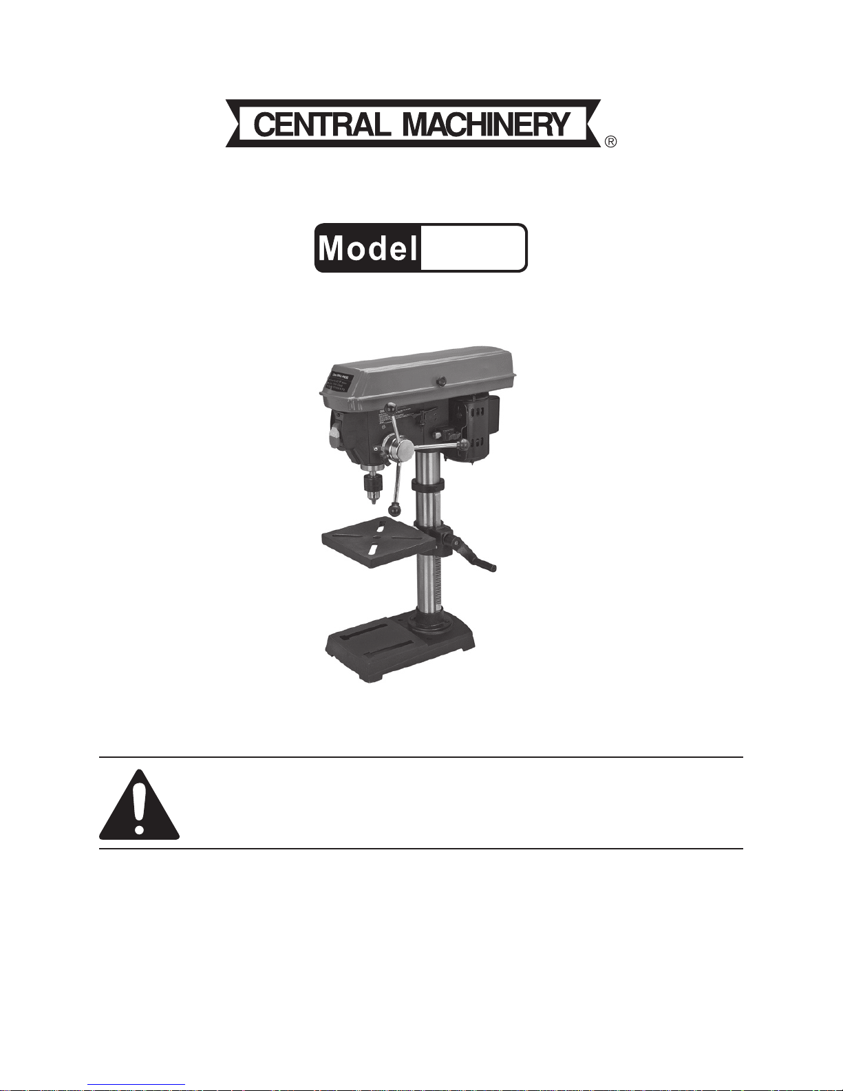
10” DRILL PRESS WITH LASER
65589
SET UP AND OPERATING INSTRUCTIONS
Visit our website at: http://www.harborfreight.com
Read this material before using this product.
Failure to do so can result in serious injury.
SAVE THIS MANUAL.
Copyright© 2008 by Harbor Freight Tools®. All rights reserved. No portion of this manual or any artwork
contained herein may be reproduced in any shape or form without the express written consent of
Harbor Freight Tools. Diagrams within this manual may not be drawn proportionally. Due to continuing
improvements, actual product may differ slightly from the product described herein. Tools required for
assembly and service may not be included.
For technical questions or replacement parts, please call 1-800-444-3353.
Revised Manual 09k
Page 2

SAVE THIS MANUAL
Keep this manual for the safety warnings and precautions, assembly, operating, inspection, maintenance and cleaning
procedures. Write the product’s serial
number in the back of the manual near the
assembly diagram (or month and year of
purchase if product has no number). Keep
this manual and the receipt in a safe and
dry place for future reference.
NOTICE is used to
address practices
not related to personal injury.
CAUTION, without
the safety alert
symbol, is used to address
practices not related to
personal injury.
General Power Tool Safety
Warnings
IMPORTANT SAFETY
INFORMATION
In this manual, on the labeling,
and all other information provided with this product:
This is the safety alert
symbol. It is used to alert
you to potential personal
injury hazards. Obey all
safety messages that
follow this symbol to avoid
possible injury or death.
DANGER indicates
a hazardous
situation which, if not
avoided, will result in death or
serious injury.
WARNING
indicates a
hazardous situation which, if
not avoided, could result in
death or serious injury.
CAUTION, used
with the safety
alert symbol, indicates a
hazardous situation which, if
not avoided, could result in
minor or moderate injury.
WARNING Read all safety
warnings and instructions.
Failure to follow the warnings and
instructions may result in electric
shock, re and/or serious injury.
Save all warnings and
instructions for future reference.
The term ″power tool″ in the
warnings refers to your mains-
operated (corded) power tool or
battery-operated (cordless) power
tool.
Work area safety1.
Keep work area clean and well lit. a.
Cluttered or dark areas invite acci-
dents.
Do not operate power tools in b.
explosive atmospheres, such as in
the presence of ammable liquids,
gases or dust. Power tools create
sparks which may ignite the dust or
fumes.
Keep children and bystanders c.
away while operating a power tool.
Distractions can cause you to lose
control.
Electrical safety2.
Power tool plugs must match the a.
outlet. Never modify the plug in
any way. Do not use any adapter
SKU 65589 For technical questions, please call 1-800-444-3353. Page 2
Page 3

plugs with grounded power tools.
Unmodied plugs and matching outlets will reduce risk of electric shock.
Avoid body contact with grounded b.
surfaces such as pipes, radiators,
ranges and refrigerators. There is
an increased risk of electric shock if
your body is grounded.
Do not expose power tools to rain c.
or wet conditions. Water entering
a power tool will increase the risk of
electric shock.
Do not abuse the cord. Never use d.
the cord for carrying, pulling or
unplugging the power tool. Keep
cord away from heat, oil, sharp
edges or moving parts. Damaged
or entangled cords increase the risk
of electric shock.
When operating a power tool out-e.
doors, use an extension cord suitable for outdoor use. Use of a cord
suitable for outdoor use reduces the
risk of electric shock.
If operating a power tool in a damp f.
location is unavoidable, use a
Ground Fault Circuit Interrupter
(GFCI) protected supply. Use of
a GFCI reduces the risk of electric
shock.
Personal safety3.
Stay alert, watch what you are do-a.
ing and use common sense when
operating a power tool. Do not use
a power tool while you are tired
or under the inuence of drugs,
alcohol or medication. A moment
of inattention while operating power
tools may result in serious personal
injury.
Use safety equipment. Always b.
wear eye protection. Safety equip-
ment such as dust mask, non-skid
safety shoes, hard hat, or hearing
protection used for appropriate conditions will reduce personal injuries.
Prevent unintentional starting. c.
Ensure the switch is in the off-position before connecting to power
source and/or battery pack, picking up or carrying the tool. Carry-
ing power tools with your nger on
the switch or energizing power tools
that have the switch on invites acci-
dents.
Remove any adjusting key or d.
wrench before turning the power
tool on. A wrench or a key left at-
tached to a rotating part of the power
tool may result in personal injury.
Do not overreach. Keep proper e.
footing and balance at all times.
This enables better control of the
power tool in unexpected situations.
Dress properly. Do not wear loose f.
clothing or jewelry. Keep your
hair, clothing and gloves away
from moving parts. Loose clothes,
jewelry or long hair can be caught in
moving parts.
If devices are provided for the con-g.
nection of dust extraction and collection facilities, ensure these are
connected and properly used. Use
of these devices can reduce dust-
related hazards.
Only use safety equipment that h.
has been approved by an appropriate standards agency. Unapproved
safety equipment may not provide
adequate protection. Eye protection
must be ANSI-approved and breathing protection must be NIOSH-approved for the specic hazards in the
work area.
SKU 65589 For technical questions, please call 1-800-444-3353. Page 3
Page 4

Power tool use and care4.
Do not force the power tool. Use a.
the correct power tool for your application. The correct power tool will
do the job better and safer at the rate
for which it was designed.
Do not use the power tool if the b.
switch does not turn it on and off.
Any power tool that cannot be controlled with the switch is dangerous
and must be repaired.
Disconnect the plug from the c.
power source and/or the battery
pack from the power tool before
making any adjustments, changing accessories, or storing power
tools. Such preventive safety mea-
sures reduce the risk of starting the
power tool accidentally.
Store idle power tools out of the d.
reach of children and do not allow
persons unfamiliar with the power
tool or these instructions to operate the power tool. Power tools are
dangerous in the hands of untrained
users.
Maintain power tools. Check for e.
misalignment or binding of moving
parts, breakage of parts and any
other condition that may affect the
power tool’s operation. If damaged, have the power tool repaired
before use. Many accidents are
caused by poorly maintained power
tools.
Keep cutting tools sharp and f.
clean. Properly maintained cutting
tools with sharp cutting edges are
less likely to bind and are easier to
control.
Use the power tool, accessories g.
and tool bits etc. in accordance
with these instructions, taking into
account the working conditions
and the work to be performed. Use
of the power tool for operations different from those intended could result
in a hazardous situation.
Service5.
Have your power tool serviced by a.
a qualied repair person using
only identical replacement parts.
This will ensure that the safety of the
power tool is maintained.
This product is not a toy. 6. Keep it
out of reach of children.
People with pacemakers should 7.
consult their physician(s) before
use. Electromagnetic elds in close
proximity to heart pacemaker could
cause pacemaker interference or
pacemaker failure. In addition, people with pacemakers should:
Avoid operating alone.•
Do not use with power switch •
locked on.
Properly maintain and inspect to •
avoid electrical shock.
Any power cord must be properly •
grounded. Ground Fault Circuit
Interrupter (GFCI) should also be
implemented – it prevents sustained
electrical shock.
Some dust created by power sand-8.
ing, sawing, grinding, drilling,
and other construction activities,
contains chemicals known [to the
State of California] to cause cancer, birth defects or other reproductive harm. Some examples of
these chemicals are:
Lead from lead-based paints•
SKU 65589 For technical questions, please call 1-800-444-3353. Page 4
Page 5

Crystalline silica from bricks and ce-•
ment or other masonry products
Arsenic and chromium from chemi-•
cally treated lumber
Your risk from these exposures varies, depending on how often you do
this type of work. To reduce your
exposure to these chemicals: work in
a well ventilated area, and work with
approved safety equipment, such as
those dust masks that are specially
designed to lter out microscopic
particles. (California Health & Safety
Code § 25249.5, et seq.)
The warnings, precautions, and in-9.
structions discussed in this instruction
manual cannot cover all possible conditions and situations that may occur.
It must be understood by the operator
that common sense and caution are
factors which cannot be built into this
product, but must be supplied by the
operator.
Specic Drill Press Warnings
Secure the Drill Press Base (1) to the 1.
oor using Bolts (not supplied). The
oor must be level, smooth and able
to support the weight of the drill press
and workpieces.
Setup the Drill Press in an area 2.
where you can walk around it unhampered.
Avoid possible kickback and grab-3.
bing by clamping the workpiece to the
table, or use a vise that is secured
to the table. If the workpiece begins
to spin, do not attempt to stop it with
your hands. Turn the Motor (36) off
and wait until it stops spinning before
attempting to remove it.
Avoid being caught and pulled into 4.
the spinning Chuck (81). Do not wear
gloves, long sleeve shirts, ties or
jewelry. Long hair must be bundled
behind the head.
Do not leave Drill Press running while 5.
unattended. Turn power OFF.
Do not place hands or arms near the 6.
workpiece; this will help prevent the
possibility of the workpiece coming
loose and causing injury.
Before drilling, turn on the Motor 7.
and check for bit wobble or machine
vibration. If any is found, correct the
problem before drilling.
Set the proper spindle speed for the 8.
specic drilling operation.
When nished, turn off the Drill Press 9.
and remove the Switch Key (64).
Do not mount or adjust the workpiece 10.
on the Table (15) while the Motor is
running.
When drilling or cutting large holes, 11.
use the slower speeds and securely
fasten the workpiece to the Table
using a mounted vise or clamps (not
included).
Do not use drill bits that extend more 12.
than six inches from the Chuck (81).
Do not use circle cutters, rotary plan-13.
ers, wire wheels, router bits, or shape
cutters on this Drill Press.
The laser guide will NOT turn off 14.
automatically. Use the Laser Switch
(53) on side of Cell Box (49) to turn
off laser. Doing so will help prevent
accidental eyes exposure to laser
beam.
SKU 65589 For technical questions, please call 1-800-444-3353. Page 5
Page 6

Do not remove laser and use it for a 15.
purpose for which it was not intended.
CAUTION!16. To prevent injury, position
batteries in proper polarity and do
not install batteries of different types,
charge levels, or capacities together.
Vibration Safety
This tool vibrates during use. Repeated or long-term exposure to vibration may cause temporary or permanent
physical injury, particularly to the hands,
arms and shoulders. To reduce the risk of
vibration-related injury:
Include vibration-free periods each 5.
day of work.
Grip tool as lightly as possible (while 6.
still keeping safe control of it). Let
the tool do the work.
To reduce vibration, maintain the tool 7.
as explained in this manual. If any
abnormal vibration occurs, stop use
immediately.
SAVE THESE
INSTRUCTIONS.
GROUNDING
Anyone using vibrating tools regu-1.
larly or for an extended period should
rst be examined by a doctor and
then have regular medical check-
ups to ensure medical problems are
not being caused or worsened from
use. Pregnant women or people
who have impaired blood circulation
to the hand, past hand injuries, ner-
vous system disorders, diabetes, or
Raynaud’s Disease should not use
this tool. If you feel any medical or
physical symptoms related to vibra-
tion (such as tingling, numbness, and
white or blue ngers), seek medical
advice as soon as possible.
Do not smoke during use. Nico-2.
tine reduces the blood supply to the
hands and ngers, increasing the risk
of vibration-related injury.
TO PREVENT
ELECTRIC SHOCK
AND DEATH FROM
INCORRECT GROUNDING
WIRE CONNECTION:
Check with a qualied
electrician if you are in doubt
as to whether the outlet is
properly grounded. Do not
modify the power cord plug
provided with the tool. Never
remove the grounding prong
from the plug. Do not use the
tool if the power cord or plug
is damaged. If damaged, have
it repaired by a service facility
before use. If the plug will not
t the outlet, have a proper
outlet installed by a qualied
electrician.
Wear suitable gloves to reduce the 3.
vibration effects on the user.
Use tools with the lowest vibration 4.
when there is a choice between different processes.
SKU 65589 For technical questions, please call 1-800-444-3353. Page 6
Page 7

Grounded Tools: Tools with Three
Prong Plugs
Double Insulated Tools: Tools
with Two Prong Plugs
1. Tools marked with “Grounding Required” have a three wire cord and
three prong grounding plug. The
plug must be connected to a properly
grounded outlet. If the tool should
electrically malfunction or break
down, grounding provides a low
resistance path to carry electricity
away from the user, reducing the risk
of electric shock. (See 3-Prong Plug
and Outlet.)
The grounding prong in the plug is 2.
connected through the green wire inside the cord to the grounding system
in the tool. The green wire in the cord
must be the only wire connected to
the tool’s grounding system and must
never be attached to an electrically
“live” terminal. (See 3-Prong Plug
and Outlet.)
The tool must be plugged into an 3.
appropriate outlet, properly installed
and grounded in accordance with all
codes and ordinances. The plug and
outlet should look like those in the
preceding illustration. (See 3-Prong
Plug and Outlet.)
1. Tools marked “Double Insulated” do
not require grounding. They have
a special double insulation system
which satises OSHA requirements
and complies with the applicable
standards of Underwriters Laboratories, Inc., the Canadian Standard
Association, and the National Electrical Code. (See Outlets for 2-Prong
Plug.)
Double insulated tools may be used 2.
in either of the 120 volt outlets shown
in the preceding illustration. (See
Outlets for 2-Prong Plug.)
Extension Cords
Grounded1. tools require a three wire
extension cord. Double Insulated
tools can use either a two or three
wire extension cord.
As the distance from the supply outlet 2.
increases, you must use a heavier
gauge extension cord. Using extension cords with inadequately sized
wire causes a serious drop in voltage,
resulting in loss of power and possible tool damage.
(See Table A.) The smaller the
gauge number of the wire, the greater
the capacity of the cord. For ex-
SKU 65589 For technical questions, please call 1-800-444-3353. Page 7
Page 8

ample, a 14 gauge cord can carry a
higher current than a 16 gauge cord.
(See Table A.)
When using more than one exten-3.
sion cord to make up the total length,
make sure each cord contains at
least the minimum wire size required.
(See Table A.)
If you are using one extension cord 4.
for more than one tool, add the
nameplate amperes and use the sum
to determine the required minimum
cord size. (See Table A.)
If you are using an extension cord 5.
outdoors, make sure it is marked with
the sufx “W-A” (“W” in Canada) to
indicate it is acceptable for outdoor
use.
RECOMMENDED MINIMUM WIRE
GAUGE FOR EXTENSION CORDS*
(120/240 VOLT)
EXTENSION CORD
NAMEPLATE
LENGTH
AMPERES
(at full load)
0 – 2.0 18 18 18 18 16
2.1 – 3.4 18 18 18 16 14
3.5 – 5.0 18 18 16 14 12
5.1 – 7.0 18 16 14 12 12
7.1 – 12.0 18 14 12 10 -
12.1 – 16.0 14 12 10 - -
16.1 – 20.0 12 10 - - -
TABLE A
25’
50’
75’
100’
* Based on limiting the line
voltage drop to ve volts at
150% of the rated amperes.
Symbology
150’
Make sure the extension cord is prop-6.
erly wired and in good electrical condition. Always replace a damaged
extension cord or have it repaired by
a qualied electrician before using it.
Protect the extension cords from 7.
sharp objects, excessive heat, and
damp or wet areas.
V~
A
n0 xxxx/min.
Double Insulated
Canadian Standards Association
Underwriters Laboratories, Inc.
Volts Alternating Current
Amperes
No Load Revolutions per Minute
(RPM)
SKU 65589 For technical questions, please call 1-800-444-3353. Page 8
Page 9

SPECIFICATIONS
Electrical
Requirements
Spindle Pulley
Speeds (RPM)
Column 2-5/16” (diameter) tube
Base Dimensions 13” L x 8” W x 1-7/8” H
Throat Depth 5” Deep
Chuck/Capacity
Table Slot 2-7/8” L x 9/16” W
Table Rotation
Table Size 12” L x 11-3/4” W x 2-7/8” H
Laser Batteries
120 V~ / 60 Hz / 1/4 HP
570, 900, 1390, 2050, 3050
Keyed, 3-Jaw Chuck
1/16” - 1/2” diameter
0-45° In 1° Increments
(Right and Left)
(2) 1.5V “AA” Batteries (not
included)
LASER LIGHT
DO NOT STARE INTO BEAM
Max. Power Output: < 1mW,
Wavelength: 640-660 nm
CLASS II LASER PRODUCT
This product complies with
21 CFR 1040.10 and 1040.11
CEN-TECH
3491 Mission Oaks Blvd.,
Camarillo, CA, USA, 93011
Manufacture Date: ___________, _______
Note: For additional information regarding
parts listed, refer to Assembly Diagram near end of this manual.
Assembly
Position Base (1) on oor, on spot 1.
able to support weight of Drill Press.
Place Support Column (2) on Base 2.
and align holes in Support Column
with holes on Base.
Using wrench (not included) fasten 3.
Support Column to Base using four
Hex Head Screws (3). Tighten until
secure. See Figure A, below.
Hex Head
Screws (3)
Support
Column (2)
Figure A
Rack (5)
Base (1)
INSTRUCTIONS FOR
PUTTING INTO USE
Read the ENTIRE IMPORTANT
SAFETY INFORMATION
section at the beginning of this
manual including all text under
subheadings therein before set
up or use of this product.
TO PREVENT
SERIOUS INJURY
FROM ACCIDENTAL
OPERATION: Turn the Power
Switch of the tool to its “OFF”
position and unplug the tool
from its electrical outlet
before assembling or making
any adjustments to the tool.
Loosen the set screw in the Rack 4.
Collar (7) with Hex Wrench and
remove Rack Collar from Support
Column. See Figure B, below.
Rack Collar
(7)
Hex Wrench
Support
Column (2)
Rack (5)
Figure B
Insert the Elevation Shaft (13) into 5.
the Table Support (11) and slide the
Shaft through the opening as far as
possible. Then thread the Crank (10)
onto the end of the Elevation Shaft
SKU 65589 For technical questions, please call 1-800-444-3353. Page 9
Page 10

and fasten into place with Hex Socket
Screw (9). See Figure C, below.
Elevation Shaft (13)
Table Support
Hex Socket
Screw (9)
Figure C
Before Rack (5) assembly, make sure 6.
there are no burrs or nicks along its
at edge where it would rest against
Column Tube (4). With smooth end
of Rack pointing upward, slide Rack
down and through large opening in
Table Support. Set Rack against
gear mechanism on inside of Table
Support. See Figure D, below.
Rack (5)
Table Support
(11)
Mechanism
Table
(15)
While holding Rack and Table Sup-7.
port together in engaged position,
slide them over Column Tube. Continue sliding Rack down Tube until
Rack is positioned against lower Column support. See Figure E, below.
Table Support (11)
Rack (5)
Table
(15)
Figure E
Support Column
(2) Base
(11)
Crank (10)
Gear
Figure D
Place Rack Collar (7) and position 8.
it bevel side down over Rack. To
let Rack glide over Support Column
when the Table is swung to left or
right around Column, the Collar must
sit loosely over Rack and should
not be wedged against the Column.
Tighten Socket Screw (6) to keep
Collar in place. See Figure F, below.
Rack Collar
(7)
Hex Wrench
Support
Column (2)
Rack (5)
Figure F
CAUTION!9. To avoid Column or Col-
lar damage, do not overtighten set
screw.
To minimize Crank backlash during 10.
use, rotate Lock Handle (8) clockwise
to fasten Table Support in place. See
Figure G, below.
Table Support
(11)
Figure G
Lock
Handle
(8)
Set the Head (28) onto the top of 11.
the Support Column. Use the Hex
Wrench to tighten the Hex Head
Screws (30) on the right side of the
Head (28), locking the head in place.
See Figure H, on following page.
SKU 65589 For technical questions, please call 1-800-444-3353. Page 10
Page 11

Head
(28)
Figure H
Hex Head
Screws (30)
OPERATING INSTRUCTIONS
Read the ENTIRE IMPORTANT
SAFETY INFORMATION
section at the beginning of this
manual including all text under
subheadings therein before set
up or use of this product.
right/left position to accommodate the
workpiece being drilled. Once properly adjusted, tighten Lock Handle (8).
Please Note: As a safe practice, the
drill bit should be centered with center hole of the Table (15).
Open the Chuck (81) and insert the 2.
drill bit in the center. Tighten with the
Chuck Key (82).
Secure the workpiece (and backup 3.
material) to the Table using a vise
and/or clamps.
Bring the drill bit down with the Feed 4.
Handle Rod (18) to where the hole is
to be drilled.
Make minor workpiece alignment
adjustments.
5. Insert the Plug Cord (85) into an
electrical outlet.
6. Insert the Switch Key (64) into the
Switch Box (68).
Tool Set Up
7. Use the Laser Localizer (23) to
adjust position of Laser and aim at
TO PREVENT
SERIOUS INJURY
FROM ACCIDENTAL
OPERATION:
Turn the Power Switch of the
tool to its “OFF” position and
unplug the tool from its
electrical outlet before
workpiece. Turn Laster Switch (53) to
ON to activate laser.
8. Push the Switch up to turn the Motor
(36) ON. Observe wobble-free
rotation of drill bit. Turn the Motor off
and unplug the cord. Loosen, and
if necessary, re-center the bit in the
Chuck.
performing any inspection,
maintenance, or cleaning
procedures.
9. Pull down on the Feed Handle Rod
and slowly drill the hole into the
workpiece.
Adjust vertical and horizontal ori-1.
entation of the Table. If necessary,
loosen the Lock Handle (8) and turn
the Crank (10) to adjust the Table
(15) height and and slide the table to
10. Warning! If the drill bit grabs
and spins the workpiece, do not
attempt to stop the spinning
with your hands. Step back, and
push the Switch down to the OFF
SKU 65589 For technical questions, please call 1-800-444-3353. Page 11
Page 12

position. Wait for the spindle to
stop turning before dislodging the
workpiece.
11. When the drilling is complete, press
the Switch to the OFF position and
remove the Switch Key to prevent
any unauthorized use.
Turn the Drill Press ON, activate 6.
Laser, and turn the Feed Handle Rod
counterclockwise to drill the hole.
While drilling, watch the pointer and
scale on the Rack Collar. Stop turning the Feed Handle Rod when the
pointer and scale indicate the desired
depth.
Setting Depth Scale
Secure the workpiece to the Table.1.
Mark the desired hole depth on the 2.
side of the workpiece.
Loosen the Depth Stop Ring (21).3.
Turn the Feed Handle Rod counter-4.
clockwise to bring the tip of the drill
bit down, next to the hole depth mark.
Turn the Rack Collar (7) counter-5.
clockwise until it stops moving.
Tighten the Depth Stop Ring.6.
Turn the Drill Press ON, activate 7.
Laser, and turn the Feed Handle Rod
counterclockwise until it drills the hole
and stops at the set depth.
Deactivate Laser and turn the Drill 8.
Press OFF.
Deactivate Laser and turn the Drill 7.
Press OFF.
Locking Chuck at Specic Depth
Loosen the Depth Stop Ring.1.
2. Turn the Feed Handle Rod
counterclockwise to bring the Chuck
(81) to the desired depth.
3. Turn the Rack Collar clockwise until it
stops.
4. Tighten the Depth Stop Ring. The
Chuck will be held at this position
when the Feed Handle Rod is
released.
Tilting The Table
Loosen the Head Screw (16).1.
Loosen the Lock Handle (8).2.
Measuring Depth While Drilling
Secure the workpiece to the Table.1.
Loosen the Depth Stop Ring.2.
Adjust the Table height so that the tip 3.
of the drill bit is just above the workpiece.
Turn the Rack Collar clockwise to “0”.4.
Tighten the Depth Stop Ring.5.
SKU 65589 For technical questions, please call 1-800-444-3353. Page 12
Rotate the Table to the desired angle. 3.
The scale can be used to approximate the angle.
Retighten the Lock Handle, then the 4.
Head Screw.
Removing and Installing Chuck
Adjust the Rack Collar to hold the 1.
Chuck at a depth of three inches.
Align the key holes in the Spindle 2.
Shaft (80) and the Drill Tube (78) by
turning the Chuck by hand.
Page 13

Insert the Nip Key (74) into the key 3.
holes.
place and, using a wrench, remove
the (outer) Hex Nut (57) only.
Lightly tap the Nip Key with a rubber 4.
mallet until the Chuck falls out of the
Spindle.
To install Chuck, slide the Chuck as-5.
sembly up and into the Spindle.
Turn until the rectangular end of the 6.
Chuck slips into the notch on the
Spindle Shaft.
Warning! If the Chuck is not prop-7.
erly set in the Spindle Shaft notch,
it may y out during operation.
Loosen the Lock Handle (8) and raise 8.
the Table about three inches below
the Chuck.
4. Turn the Chuck sleeve clockwise to
open the jaws completely.
5. Turn the Feed Handle Rod
counterclockwise and force the
Chuck against Table until secure.
Adjusting Drill Tube Spring
WARNING! Be sure to wear ANSI-1.
approved safety goggle and full
face shield during this procedure.
Loosen the Depth Stop Ring.2.
Move the Chuck to its uppermost 3.
position.
With the screwdriver still in place, 7.
loosen the (inner) Hex Nut (57) until
the Spring Cap notch disengages
from the Spring Retainer (54) -- about
1/8 inch.
Turn the screwdriver counterclock-8.
wise and engage the next Spring
Cap notch. Leave the screwdriver in
place.
Tighten the (inner) Hex Nut just 9.
enough to engage the notch. If this
Hex Nut is too tight, it will restrict (up
and down) Chuck movement.
Turn the Feed Handle Rod and check 10.
the tension of the Spring (55), making
sure the up movement is smooth and
complete.
From one inch down, the Chuck
should return to its uppermost position. If more tension is required,
repeat steps 5 through 9.
Replace the (outer) Hex Nut and 11.
tighten on top of the (inner) Hex Nut.
Do not overtighten.
If the (up/down) movement is restrict-12.
ed, slightly loosen the (inner) Hex
Nut, and retighten the (outer) Hex
Nut.
Turn the Rack Collar clockwise until it 4.
stops.
Tighten the Depth Stop Ring. This 5.
will prevent the Chuck from dropping
during Drill Tube’s Spring (55) adjustment.
Insert a screwdriver in the lower-front 6.
notch of Spring Cap (56). Hold it in
SKU 65589 For technical questions, please call 1-800-444-3353. Page 13
Replacing the V-Belt
Turn Knob (40) located on top of 1.
Guard (39) counterclockwise.
Lift open Guard lid.2.
Before removing the V-Belt, the belt 3.
tension must be released to allow for
belt removal.
Page 14

Guard
(39)
Figure I
Head
(28)
Screwdriver
Motor
Adjustment
Knob (22)
To do this, rst turn both Motor Ad-4.
justing Knobs (22) counterclockwise
(There is one on each side.) See
Figure 1, next page.
Push the Motor (36) forward, re-5.
leasing tension on the V-Belt (38).
Remove or reposition V-Belt. See
Figure I, above.
Motor
Mount
(32)
Motor
(36)
Tun the Motor Adjustment Knob 10.
clockwise to lock Motor Mount and
Motor in place.
Close Guard lid and lock lid into place 11.
by turning Knob clockwise.
WARNING!12. Do not activate Drill
Press until Guard is locked.
To tighten belt tension, use a screw-6.
driver (not included) and press the
end against the Motor Mount (32).
See Figure I, above.
Apply pressure on screwdriver so that 7.
Motor Mount and Motor (36) slide
away from Head (28).
Remove old V-Belt (38) from around 8.
Spindle Pulley (58). Then slide other
end of V-Belt off Motor Pulley (37).
MAINTENANCE AND
SERVICING
Procedures not specically
explained in this manual
must be performed only by a
qualied technician.
TO PREVENT
SERIOUS INJURY
FROM ACCIDENTAL
OPERATION: Turn Power
Wrap end of new V-Belt around top of 9.
Motor Pulley. Then slide other end of
V-Belt around top of Spindle Pulley.
Rotate the Pulley until the Belt is set
in Pulley groove.
Switch to its “OFF” position
and unplug tool from its
electrical outlet before
performing any inspection or
maintenance.
SKU 65589 For technical questions, please call 1-800-444-3353. Page 14
Page 15

TO PREVENT SERIOUS
INJURY FROM TOOL
FAILURE: Do not use
damaged equipment. If
abnormal noise or vibration
occurs, have the problem
corrected before further use.
Cleaning, Maintenance, and
Lubrication
If operating Drill Press on a regular 10.
basis, make sure to lubricate Spindle
Shaft (80) each week with a light oil.
Store in a clean and dry location11. .
To replace the laser batteries, lift the 12.
cover off the laser housing. Replace
the batteries with two “AA” batteries
and close the cover. See Figure D,
below.
BEFORE EACH USE,1. inspect the
general condition of the Drill Press.
Check for loose screws, misalignment
or binding of moving parts, cracked,
bent, or broken parts, damaged electrical wiring, and any other condition
that may affect its safe operation.
AFTER USE,2. use compressed air to
blow-clean the Table (15), Base (1)
and Motor (36) cooling vents of dirt
and materials.
Also blow-clean any dirt from the Cell 3.
Box (49) and Laser Switch (53).
Apply a coat of paste wax (not includ-4.
ed) to Table and Support Column (2)
to help keep the surfaces clean.
All Bear Bearings (61,76) are factory 5.
lubricated and need no additional
lubrication.
CAUTION!13. To prevent injury, position
batteries in proper polarity and do
not install batteries of different types,
charge levels, or capacities together.
14. WARNING! If the supply cord of
this power tool is damaged, it must
be replaced only by a qualied
service technician.
PERIODICALLY6. , lubricate the Tube
Column, Spindle Shaft grooves, and
Drill Tube (78).
PERIODICALLY7. , grease the rack.
MONTHLY8. , check the tightness of
all mounting screws and bolts in the
Base, Column and Head assemblies.
Check belts for wear and replace if 9.
frayed or damaged in any way.
SKU 65589 For technical questions, please call 1-800-444-3353. Page 15
Page 16

Troubleshooting
Problem Possible Causes Likely Solutions
Noisy operation Incorrect belt tension.1.
Drill bit burns Incorrect Speed1.
Drill bit leaves a
hole that is not
round
Wood splinters on
underside
Workpiece torn
loose from hand.
Drill bit binds in
workpiece
Excessive drill bit
runout or wobble
Quill returns too
slow or too fast
Chuck will not stay
on Spindle Shaft;
falls off when trying
to install it.
Dry Spindle Shaft (80).2.
Loose Spindle Pulley (58). 3.
Loose Motor Pulley (37).4.
Chips not coming out of hole.2.
Dull drill bit.3.
Feeding too slow.4.
Not lubricated.5.
Hard grain in wood or lengths 1.
of cutting lips and/or angles not
equal.
Bent drill bit.2.
No “back-up” material under 1.
workpiece.
Not supported or clamped 1.
properly.
Workpiece pinching drill bit or 1.
excessive feed pressure.
Improper belt tension.2.
Bent drill bit.1.
Worn Spindle Ball Bearings (76).2.
Drill bit not properly installed in 3.
Chuck (81).
Chuck not properly installed.4.
Spring has improper tension.1. Adjust Spring (55) tension.1.
Dirt, grease or oil present on 1.
inside of Chuck or on Spindle
Shaft tapered surface.
Adjust belt tension.1.
Lubricate Spindle Shaft.2.
Check tightness of Retaining Ring (59); 3.
tighten if necessary.
Tighten set screws in pulleys.4.
Adjust to correct speed.1.
Retract drill bit frequently to clear chips.2.
Resharpen drill bit.3.
Feed fast enough, allowing drill bit to cut.4.
Lubricate drill bit.5.
Resharpen drill bit correctly. 1.
Replace drill bit.2.
Use “back-up” material.1.
Support or clamp workpiece.1.
Support or clamp workpiece. 1.
Adjust belt tension.2.
Use a straight drill bit.1.
Replace Ball Bearings.2.
Install drill bit properly. 3.
Install Chuck properly.4.
Clean tapered surface of Chuck and Spindle 2.
Shaft, removing all dirt, grease and oil.
Follow all safety precautions whenever diagnosing or servicing the
tool. Disconnect power supply before service.
PLEASE READ THE FOLLOWING CAREFULLY
THE MANUFACTURER AND/OR DISTRIBUTOR HAS PROVIDED THE PARTS LIST AND ASSEMBLY DIAGRAM
IN THIS MANUAL AS A REFERENCE TOOL ONLY. NEITHER THE MANUFACTURER OR DISTRIBUTOR MAKES
ANY REPRESENTATION OR WARRANTY OF ANY KIND TO THE BUYER THAT HE OR SHE IS QUALIFIED
TO MAKE ANY REPAIRS TO THE PRODUCT, OR THAT HE OR SHE IS QUALIFIED TO REPLACE ANY PARTS
OF THE PRODUCT. IN FACT, THE MANUFACTURER AND/OR DISTRIBUTOR EXPRESSLY STATES THAT
ALL REPAIRS AND PARTS REPLACEMENTS SHOULD BE UNDERTAKEN BY CERTIFIED AND LICENSED
TECHNICIANS, AND NOT BY THE BUYER. THE BUYER ASSUMES ALL RISK AND LIABILITY ARISING OUT OF
HIS OR HER REPAIRS TO THE ORIGINAL PRODUCT OR REPLACEMENT PARTS THERETO, OR ARISING OUT
OF HIS OR HER INSTALLATION OF REPLACEMENT PARTS THERETO.
SKU 65589 For technical questions, please call 1-800-444-3353. Page 16
Page 17

PARTS LIST
Part Description Q’ty
1 Base 1
2 Support Column 1
3 Hex Head Screw (M8 x 20) 4
4 Column Tube 1
5 Rack 1
6 Hex Socket Screw (M8 x 10) 3
7 Rack Collar 1
8 Lock Handle 1
9 Hex Socket Screw (M6 x 10) 1
10 Crank 1
11 Table Support 1
12 Gear Pin 1
13 Elevation Shaft 1
14 Gear 1
15 Table 1
16 Hex Head Screw (M12 x 25) 1
17 Knob 3
18 Feed Handle Rod 3
19 Hub 1
20 Shaft Pinion 1
21 Depth Stop Ring 1
22 Motor Adjusting Knob 3
23 Laser Localizer 2
24 Pin Stop 1
25 Hex Socket Screw (M8 x 8) 2
26 Hex Socket Screw (M8 x 8) 2
27 Roll Pin 2
28 Head 1
29 Motor Support 2
30 Hex Head Screw (M8 x 16) 4
31 Washer 8
32 Motor Mount 1
33 Lock Washer 2
34 Hex Nut (M10) 2
35 Hex Nut (M8) 4
36 Motor 1
37 Motor Pulley 1
38 V-Belt 1
39 Guard 1
40 Knob 1
41 Pan Screw (M5 x 12) 1
42 Pan Screw (M5 x 10) 2
43 Clamp Cord 3
PARTS LIST
Part Description Q’ty
44 Pan Screw (M6 x 8) 4
45 Washer 4
46 Rubber Circle 4
47 Rubber Bushing 2
48 Spring 1
49 Cell Box 1
50 Pan Screw (M4 x 10) 2
51 Cell 2
52 Cell Box Lid 1
53 Laser Switch 1
54 Spring Retainer 1
55 Spring 1
56 Spring Cap 1
57 Hex Nut (M12) 2
58 Spindle Pulley 1
59 Retaining Ring 1
60 Pulley Insert 1
61 Bearing Ball 2
62 Spacer 1
63 Retaining Ring 1
64 Switch Key 1
65 Pan Head Screw 3
66 Switch Plate 1
67 Pan Screw (M5 x 14) 2
68 Switch Box 1
69 Hex Nut (M8) 1
70 Socket Set Screw 1
71 Hex Socket Screw (M8 x 8) 1
72 Washer 2
73 Pan Head Screw (M5 x 6) 2
74 Nip Key 1
75 Pan Head Screw (M5 x 10) 1
76 Ball Bearing 2
77 Drill Gasket 1
78 Drill Tube 1
79 Retaining Ring 1
80 Spindle Shaft 1
81 Chuck 1
82 Chuck Key 1
83 Hex Wrench 1 1
84 Hex Wrench 2 1
85 Plug Cord 1
SKU 65589 For technical questions, please call 1-800-444-3353. Page 17
Page 18

ASSEMBLY DIAGRAM
Record Product’s Serial Number Here:
Note: If product has no serial number, record month and year of purchase instead.
Note: Some parts are listed and shown for illustration purposes only, and are not avail-
able individually as replacement parts.
SKU 65589 For technical questions, please call 1-800-444-3353. Page 18
Page 19

WIRING DIAGRAM
SKU 65589 For technical questions, please call 1-800-444-3353. Page 19
Page 20

LIMITED 90 DAY WARRANTY
Harbor Freight Tools Co. makes every effort to assure that its products meet high
quality and durability standards, and warrants to the original purchaser that this product is free from defects in materials and workmanship for the period of 90 days from
the date of purchase. This warranty does not apply to damage due directly or indirectly,
to misuse, abuse, negligence or accidents, repairs or alterations outside our facilities,
criminal activity, improper installation, normal wear and tear, or to lack of maintenance.
We shall in no event be liable for death, injuries to persons or property, or for incidental,
contingent, special or consequential damages arising from the use of our product. Some
states do not allow the exclusion or limitation of incidental or consequential damages, so
the above limitation of exclusion may not apply to you. THIS WARRANTY IS EXPRESSLY IN LIEU OF ALL OTHER WARRANTIES, EXPRESS OR IMPLIED, INCLUDING THE
WARRANTIES OF MERCHANTABILITY AND FITNESS.
To take advantage of this warranty, the product or part must be returned to us with
transportation charges prepaid. Proof of purchase date and an explanation of the complaint must accompany the merchandise. If our inspection veries the defect, we will either repair or replace the product at our election or we may elect to refund the purchase
price if we cannot readily and quickly provide you with a replacement. We will return repaired products at our expense, but if we determine there is no defect, or that the defect
resulted from causes not within the scope of our warranty, then you must bear the cost
of returning the product.
This warranty gives you specic legal rights and you may also have other rights
which vary from state to state.
3491 Mission Oaks Blvd. • PO Box 6009 • Camarillo, CA 93011 • (800) 444-3353
SKU 65589 For technical questions, please call 1-800-444-3353. Page 20
 Loading...