

Page 1

10” BENCH GRINDER
6510
SET UP AND OPERATING INSTRUCTIONS
Distributed exclusively by Harbor Freight Tools®.
3491 Mission Oaks Blvd., Camarillo, CA 93011
Visit our website at: http://www.harborfreight.com
Read this material before using this product.
Failure to do so can result in serious injury.
SAVE THIS MANUAL.
Copyright© 1997 by Harbor Freight Tools®. All rights reserved. No portion of this manual or any artwork
contained herein may be reproduced in any shape or form without the express written consent of
Harbor Freight Tools. Diagrams within this manual may not be drawn proportionally. Due to continuing
improvements, actual product may differ slightly from the product described herein. Tools required for
assembly and service may not be included.
For technical questions or replacement parts, please call 1-800-444-3353.
Manual Revised 09d
Page 2

CONTENTS
UNPACKING .................................. 9
IMPORTANT SAFETY
INFORMATION ............................ 3
GENERAL TOOL SAFETY
WARNINGS ......................................3
GROUNDING INSTRUCTIONS ..... 5
110-120 V~ GROUNDED TOOLS:
TOOLS WITH THREE PRONG
PLUGS .............................................5
110-120 V~ DOUBLE INSULATED
TOOLS: TOOLS WITH TWO
PRONG PLUGS ...............................6
GRINDER SAFETY WARNINGS ........ 6
SPECIFICATIONS .......................... 9
ASSEMBLY .................................. 10
TOOL REST ASSEMBLY ................. 10
EYE SHIELD ASSEMBLY ................10
GRINDING WHEEL ASSEMBLY ...... 11
OPERATION ................................ 13
OPERATION NOTES ........................ 13
GENERAL OPERATION .................. 13
PARTS LIST ................................. 14
ASSEMBLY DIAGRAM ................ 15
LIMITED 1 YEAR / 90 DAY
WARRANTY .............................. 16
Page 2 For technical questions, please call 1-800-444-3353. SKU 6510
Page 3

SAVE THIS MANUAL
Keep this manual for the safety warnings and precautions, assembly, operating, inspection, maintenance and cleaning
procedures. Write the product’s serial
number in the back of the manual near the
assembly diagram (or month and year of
purchase if product has no number). Keep
this manual and the receipt in a safe and
dry place for future reference.
IMPORTANT SAFETY
INFORMATION
In this manual, on the labeling,
and all other information provided with this product:
This is the safety alert
symbol. It is used to alert
you to potential personal
injury hazards. Obey all
safety messages that
follow this symbol to avoid
possible injury or death.
NOTICE is used to
address practices
not related to personal injury.
CAUTION, without
the safety alert
symbol, is used to address
practices not related to
personal injury.
General Tool Safety Warnings
WARNING Read all safety
warnings and instructions.
Failure to follow the warnings and
instructions may result in electric
shock, re and/or serious injury.
Save all warnings and
instructions for future reference.
KEEP GUARDS IN PLACE and in 1.
working order.
REMOVE ADJUSTING KEYS AND 2.
WRENCHES. Form habit of checking to see that keys and adjusting
wrenches are removed from tool
before turning it on.
DANGER indicates
a hazardous
situation which, if not
avoided, will result in death or
serious injury.
WARNING
indicates a
hazardous situation which, if
not avoided, could result in
death or serious injury.
CAUTION, used
with the safety
alert symbol, indicates a
hazardous situation which, if
not avoided, could result in
minor or moderate injury.
KEEP WORK AREA CLEAN. Clut-3.
tered areas and benches invite accidents.
DON’T USE IN DANGEROUS EN-4.
VIRONMENT. Don’t use power tools
in damp or wet locations, or expose
them to rain. Keep work area well
lighted.
KEEP CHILDREN AWAY. All visitors 5.
should be kept safe distance from
work area.
MAKE WORKSHOP KID PROOF 6.
with padlocks, master switches, or by
removing starter keys.
Page 3For technical questions, please call 1-800-444-3353.SKU 6510
Page 4

DON’T FORCE TOOL. It will do the 7.
job better and safer at the rate for
which it was designed.
USE RIGHT TOOL. Don’t force tool 8.
or attachment to do a job for which it
was not designed.
glasses only have impact resistant
lenses, they are NOT safety glasses.
SECURE WORK. Use clamps or a 12.
vise to hold work when practical. It’s
safer than using your hand and it
frees both hands to operate tool.
RECOMMENDED MINIMUM WIRE
GAUGE FOR EXTENSION CORDS
(120 VOLT)
NAMEPLATE
AMPERES
(at full load)
0 – 6 18 16 16 14
6.1 – 10 18 16 14 12
10.1 – 12 16 16 14 12
12.1 – 16 14 12 Do not use.
EXTENSION CORD
LENGTH
25’ 50’ 100’ 150’
TABLE A
USE PROPER EXTENSION CORD. 9.
Make sure your extension cord is
in good condition. When using an
extension cord, be sure to use one
heavy enough to carry the current
your product will draw. An undersized
cord will cause a drop in line voltage
resulting in loss of power and overheating. Table A shows the correct
size to use depending on cord length
and nameplate ampere rating. If in
doubt, use the next heavier gauge.
The smaller the gauge number, the
heavier the cord.
WEAR PROPER APPAREL. Do not 10.
wear loose clothing, neckties, rings,
bracelets, or other jewelry which may
get caught in moving parts. Nonslip
footwear is recommended. Wear protective hair covering to contain long
hair.
ALWAYS USE SAFETY GLASSES. 11.
Also use face or dust mask if cutting
operation is dusty. Everyday eye-
DON’T OVERREACH. Keep proper 13.
footing and balance at all times.
MAINTAIN TOOLS WITH CARE. 14.
Keep tools sharp and clean for best
and safest performance. Follow
instructions for lubricating and changing accessories.
DISCONNECT TOOLS before ser-15.
vicing; when changing accessories,
such as blades, bits, cutters, and the
like.
REDUCE THE RISK OF UNINTEN-16.
TIONAL STARTING. Make sure
switch is in off position before plugging in.
USE RECOMMENDED ACCESSO-17.
RIES. Consult the owner’s manual for
recommended accessories. The use
of improper accessories may cause
risk of injury to persons.
NEVER STAND ON TOOL. Serious 18.
injury could occur if the tool is tipped
or if the cutting tool is unintentionally
contacted.
CHECK DAMAGED PARTS. Before 19.
further use of the tool, a guard or
other part that is damaged should
be carefully checked to determine
that it will operate properly and perform its intended function – check for
alignment of moving parts, binding
of moving parts, breakage of parts,
mounting, and any other conditions
that may affect its operation. A guard
Page 4 For technical questions, please call 1-800-444-3353. SKU 6510
Page 5
or other part that is damaged should
be properly repaired or replaced.
equipment-grounding conductor to a
live terminal.
DIRECTION OF FEED. Feed work 20.
into a blade or cutter against the direction of rotation of the wheel only.
GROUNDING INSTRUCTIONS
TO PREVENT
ELECTRIC SHOCK
AND DEATH FROM
INCORRECT GROUNDING
WIRE CONNECTION
READ AND FOLLOW THESE
INSTRUCTIONS:
110-120 V~ Grounded Tools: Tools
with Three Prong Plugs
In the event of a malfunction or 1.
breakdown, grounding provides a
path of least resistance for electric
current to reduce the risk of electric
shock. This tool is equipped with an
electric cord having an equipmentgrounding conductor and a grounding plug. The plug must be plugged
into a matching outlet that is properly
installed and grounded in accordance
with all local codes and ordinances.
Do not modify the plug provided – if it 2.
will not t the outlet, have the proper
outlet installed by a qualied electri-
cian.
Improper connection of the equip-3.
ment-grounding conductor can result in a risk of electric shock. The
conductor with insulation having an
outer surface that is green with or
without yellow stripes is the equipment-grounding conductor. If repair
or replacement of the electric cord or
plug is necessary, do not connect the
Check with a qualied electrician or 4.
service personnel if the grounding
instructions are not completely understood, or if in doubt as to whether the
tool is properly grounded.
Use only 3-wire extension cords that 5.
have 3-prong grounding plugs and
3-pole receptacles that accept the
tool’s plug.
Repair or replace damaged or worn 6.
cord immediately.
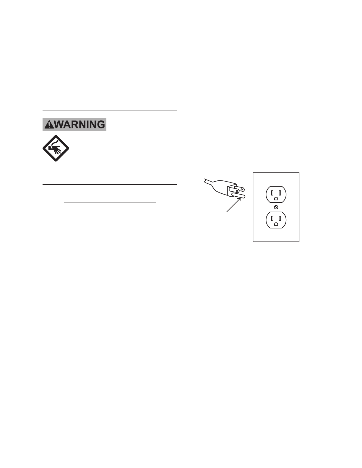
Grounding
Pin
125 V~ 3-Prong Plug and Outlet
(for up to 125 V~ and up to 15 A)
This tool is intended for use on a cir-7.
cuit that has an outlet that looks like
the one illustrated above in 125 V~
3-Prong Plug and Outlet. The tool
has a grounding plug that looks like
the plug illustrated above in 125 V~
3-Prong Plug and Outlet.
The outlet must be properly installed 8.
and grounded in accordance with all
codes and ordinances.
Do not use an adapter to connect this 9.
tool to a different outlet.
Page 5For technical questions, please call 1-800-444-3353.SKU 6510
Page 6

110-120 V~ Double Insulated
Tools: Tools with Two Prong
Plugs
Outlets for 2-Prong Plug
To reduce the risk of electric shock, 1.
double insulated equipment has a polarized plug (one blade is wider than
the other). This plug will t in a polarized outlet only one way. If the plug
does not t fully in the outlet, reverse
the plug. If it still does not t, contact
a qualied electrician to install the
proper outlet. Do not change the plug
in any way.
Double insulated tools may be used 2.
in either of the 120 volt outlets shown
in the preceding illustration. (See
Outlets for 2-Prong Plug.)
Grinder Safety Warnings
For Your Own Safety Read Instruction
Manual Before Operating Grinder
Wear eye protection.1.
Adjust distance between wheel and 7.
work rest to maintain 0.125 inch or
less separation as the diameter of the
wheel decreases with use.
Frequently clean grinding dust from 8.
beneath grinder.
Wear a full face shield over ANSI-9.
approved safety goggles during use.
Do not grind with side of wheel un-10.
less wheel is specically designed for
that type of grinding.
DO NOT OPERATE WITH ANY 11.
GUARD DISABLED, DAMAGED,
OR REMOVED. Moving guards
must move freely and close instantly.
The use of accessories or attach-12.
ments not recommended by the
manufacturer may result in a risk of
injury to persons.
When servicing use only identical 13.
replacement parts.
Only use safety equipment that has 14.
been approved by an appropriate
standards agency. Unapproved
safety equipment may not provide
adequate protection. Eye protection
must be ANSI-approved and breathing protection must be NIOSH-ap-
proved for the specic hazards in the
work area.
Use grinding wheel suitable for speed 2.
of grinder.
Replace cracked wheel immediately.3.
Always use guards and eye shields.4.
Do not overtighten wheel nut.5.
Use only anges furnished with the 6.
grinder.
Page 6 For technical questions, please call 1-800-444-3353. SKU 6510
Industrial applications must follow 15.
OSHA guidelines.
Maintain labels and nameplates on 16.
the tool. These carry important safety
information. If unreadable or missing, contact Harbor Freight Tools for a
replacement.
Page 7

Avoid unintentional starting. Prepare 17.
to begin work before turning on the
tool.
People with pacemakers should 18.
consult their physician(s) before use.
Electromagnetic elds in close proximity to heart pacemaker could cause
pacemaker interference or pacemaker failure.
The warnings, precautions, and in-21.
structions discussed in this instruction
manual cannot cover all possible conditions and situations that may occur.
It must be understood by the operator
that common sense and caution are
factors which cannot be built into this
product, but must be supplied by the
operator.
WARNING: Some dust created by 19.
power sanding, sawing, grinding,
drilling, and other construction
activities, contains chemicals
known [to the State of California] to
cause cancer, birth defects or other
reproductive harm. Some examples
of these chemicals are:
• Lead from lead-based paints
• Crystalline silica from bricks and
cement or other masonry products
• Arsenic and chromium from
chemically treated lumber
Your risk from these exposures
varies, depending on how often you
do this type of work. To reduce your
exposure to these chemicals: work in
a well ventilated area, and work with
approved safety equipment, such as
those dust masks that are specially
designed to lter out microscopic
particles.
(California Health & Safety Code §
25249.5, et seq.)
WARNING: Handling the cord on 20.
this product will expose you to lead,
a chemical known to the State of
California to cause cancer, and
birth defects or other reproductive
harm. Wash hands after handling.
(California Health & Safety Code §
25249.5, et seq.)
Vibration Safety
This tool vibrates during use. Repeated or long-term exposure to
vibration may cause temporary or
permanent physical injury, particularly
to the hands, arms and shoulders. To
reduce the risk of vibration-related
injury:
Anyone using vibrating tools regu-1.
larly or for an extended period should
rst be examined by a doctor and
then have regular medical checkups to ensure medical problems are
not being caused or worsened from
use. Pregnant women or people
who have impaired blood circulation
to the hand, past hand injuries, nervous system disorders, diabetes, or
Raynaud’s Disease should not use
this tool. If you feel any medical or
physical symptoms related to vibration (such as tingling, numbness, and
white or blue ngers), seek medical
advice as soon as possible.
Do not smoke during use. Nico-2.
tine reduces the blood supply to the
hands and ngers, increasing the risk
of vibration-related injury.
Wear suitable gloves to reduce the 3.
vibration effects on the user.
Page 7For technical questions, please call 1-800-444-3353.SKU 6510
Page 8

Use tools with the lowest vibration 4.
when there is a choice between different processes.
Include vibration-free periods each 5.
day of work.
Grip tool as lightly as possible (while 6.
still keeping safe control of it). Let
the tool do the work.
To reduce vibration, maintain the tool 7.
as explained in this manual. If any
abnormal vibration occurs, stop use
immediately.
SAVE THESE
INSTRUCTIONS.
Page 8 For technical questions, please call 1-800-444-3353. SKU 6510
Page 9

SPECIFICATIONS
Electrical Input
No Load Speed 1750 RPM
Accessory Dia. 10” Max.
Arbor Size 20mm
120 V~ / 60 Hz / 8.4 A
1 HP (rated) / 2 HP (peak)
UNPACKING
When unpacking, make sure that the
item is intact and undamaged. If any parts
are missing or broken, please call Harbor
Freight Tools at 1-800-444-3353 as soon
as possible.
Ref Description Quantity
1 Bench Grinder Unit 1
3 Eye Shield 2
4 Shield Supports 2
REV 09e
Page 9For technical questions, please call 1-800-444-3353.SKU 6510
Page 10

ASSEMBLY
The 10” Bench Grinder requires
minor assembly. The assembly
instructions below are written for the
left side but the right side is identical.
Refer to the Parts List, at the back
of this manual, for the individual part
numbers.
Tool Rest Assembly
Bolt the BENCH GRINDER UNIT (1) 1.
to a stable workplace.
Tool
Rest
(7)
Tool Rest
Knob (8)
FIGURE 1 – Removing the Tool Rest Knob
Tool
Rest
(7)
Tool Rest
Knob (8)
FIGURE 2 – Moving Tool Rest
3. Pivot the tool rest down and forward
so that it is in a horizontal position
and replace the front TOOL REST
KNOB as shown in Figure 2.
Adjust the TOOL REST (7) to the 4.
desired distance from the GRINDER
WHEEL (2). In no circumstances
should the TOOL REST be closer than 1/8” from the GRINDER
WHEEL.
Tighten both TOOL REST KNOBS.5.
2. Facing the front of the BENCH
GRINDER UNIT, remove the front
TOOL REST KNOB, and loosen the
rear TOOL REST KNOB (8) as in
Eye Shield Assembly
Bolts
(15)
Figure 1.
Eye
Shield
(3)
Washers
(17)
Attaching the Eye Shields
Nuts (16)
FIGURE 3 –
and Eye Supports
1. Attach the EYE SHIELDS (3) to
the SHIELD SUPPORTS (4) using
BOLTS (15), NUTS (16), and WASHERS (17) as shown in Figure 3.
Page 10 For technical questions, please call 1-800-444-3353. SKU 6510
Page 11

Shield
Supports
(4)
Nut
(13)
Washers
(14)
Bolt
(12)
Eye
Shield
(3)
GRINDING WHEEL ASSEMBLY
Remove Grinding Wheel
Eye
Shield (3)
Wheel
Cover (6)
Washers
(14)
Grinding
Wheel (2)
Nut (13)
FIGURE 4 –
Attaching the Eye Shield
to Wheel Cover
2. Remove the BOLT (12) and NUT (13)
from the upper grinder housing as
shown in Figure 4.
Align the EYE SHIELD Assembly 3.
with holes and replace the WHEEL
COVER BOLT and NUT.
Adjust the EYE SHIELD to the de-4.
sired position and tighten the WHEEL
COVER NUT.
Bolt
(12)
Spindle
(9)
Wheel
Mounting
Nut (10)
FIGURE 5 – Assembling the Grinder
Wheel
Mounting
Washer (11)
1. Remove both GRINDING WHEEL
COVERS (6) by unscrewing their
BOLTS (12) and NUTS (13) as shown
in Figure 5.
Place adjustable wrenches on both 2.
WHEEL MOUNTING NUTS (10).
To remove the right hand GRINDING 3.
WHEEL (2) turn its WHEEL MOUNTING NUT clockwise while keeping the
left hand WHEEL MOUNTING NUT
stationary. To remove the left hand
GRINDING WHEEL turn its WHEEL
MOUNTING NUT counterclockwise
while keeping the right hand WHEEL
MOUNTING NUT stationary.
Slide the WHEEL MOUNTING 4.
WASHER (11) off of the SPINDLE
(9).
Slide the GRINDING WHEEL off of 5.
the SPINDLE (9).
Page 11For technical questions, please call 1-800-444-3353.SKU 6510
Page 12

Installing Grinding Wheel
Note: Do not use aluminum oxide grind-
ing wheels when grinding nonferrous
metals such as aluminum and brass.
Use silicon carbide grinding wheels
for all nonferrous metals
Make sure the inside WHEEL 1.
MOUNTING WASHER (11) is on the
SPINDLE (9) with its concave side
facing out as shown in gure 5.
Place the GRINDING WHEEL (2) on 2.
the SPINDLE.
Place the outside WHEEL MOUNT-3.
ING WASHER (11) on the SPINDLE
with its concave side facing in.
Place the WHEEL MOUNTING NUT 4.
(10) on the SPINDLE and tighten.
Caution; do not over tighten the
WHEEL MOUNTING NUT as it may
crack the GRINDING WHEEL.
With the Bench Grinder running, grip 2.
the handle of the dresser rmly with
one hand and the arm of the dresser
with the other.
Using the TOOL REST (7) as sup-3.
port, apply the dresser evenly to all
surfaces of the GRINDING WHEEL.
Continue step 3 until the GRINDING 4.
WHEEL is straight and true.
Replace both WHEEL COVERS (6) 5.
and secure with their BOLTS (12),
NUTS (13), and WASHERS (14).
Dressing the Wheel
New wheels frequently are not true
and during operation often become
grooved, glazed, out of round, or
misshapen. At these times, they will
need dressing. You will need a grinding wheel dresser for this operation.
Dressers are available from Harbor
Freight Tools.
Standing to the side of the wheel, let 1.
the Bench Grinder run for a full minute with no load. If the GRINDING
WHEEL runs straight and true, you
will not need to dress it prior to operating. If it is not, proceed with the
following steps.
Page 12 For technical questions, please call 1-800-444-3353. SKU 6510
Page 13

OPERATION
General Operation
Caution: The grinding wheels must al-
ways be checked for cracks of imperfections. This is done with the “ring
test”. Tap the wheel gently near the
outer rim with the handle of a screwdriver; you should hear a clear belllike ringing. If a dull thud occurs do
not use the wheel! This means the
wheel has been damaged and will,
most likely, come apart during normal
operations.
Operation Notes
The 10” Bench Grinder comes assembled with a coarse GRINDING
WHEEL (2) and a ne GRINDING
WHEEL. Determine which wheel is
which before attempting to use the
Bench Grinder.
Obtain a tray that is large enough 1.
for the workpiece to t into, ll it with
water and place it near the Bench
Grinder.
Turn the Bench Grinder on.2.
Once the GRINDING WHEEL has 3.
reached full speed, bring the workpiece up to the wheel gently and
without jarring.
Use the TOOL REST (7) to steady 4.
the workpiece.
The workpiece will become quickly 5.
heated. Frequently quench it in water.
The workpiece will quickly become
heated. Frequently quench the workpiece in water during the grinding
process. If the metal becomes heated so much that it gets blue-colored,
it will be too soft to be useful. You
must grind off the part that is colored,
cool the workpiece, and start again.
Page 13For technical questions, please call 1-800-444-3353.SKU 6510
Page 14

PLEASE READ THE FOLLOWING CAREFULLY
THE MANUFACTURER AND/OR DISTRIBUTOR HAS PROVIDED THE PARTS LIST AND ASSEMBLY
DIAGRAM IN THIS MANUAL AS A REFERENCE TOOL ONLY. NEITHER THE MANUFACTURER OR
DISTRIBUTOR MAKES ANY REPRESENTATION OR WARRANTY OF ANY KIND TO THE BUYER THAT
HE OR SHE IS QUALIFIED TO MAKE ANY REPAIRS TO THE PRODUCT, OR THAT HE OR SHE IS
QUALIFIED TO REPLACE ANY PARTS OF THE PRODUCT. IN FACT, THE MANUFACTURER AND/
OR DISTRIBUTOR EXPRESSLY STATES THAT ALL REPAIRS AND PARTS REPLACEMENTS SHOULD
BE UNDERTAKEN BY CERTIFIED AND LICENSED TECHNICIANS, AND NOT BY THE BUYER. THE
BUYER ASSUMES ALL RISK AND LIABILITY ARISING OUT OF HIS OR HER REPAIRS TO THE
ORIGINAL PRODUCT OR REPLACEMENT PARTS THERETO, OR ARISING OUT OF HIS OR HER
INSTALLATION OF REPLACEMENT PARTS THERETO.
PARTS LIST
Part Description
1 Screw
2 Left Wheel Cover
3 Nut
4 Clamp Washer
5 Left Wheel
6 Left Wheel Guard
7 Nut
8 Left Tool Rest
9 Screw
10 Screw
11 Lockwasher
12 Left End Bell
13 Switch Plate
14 Screw
15 Bearing
16 Centrifugal Switch
17 Stator
18 Screw
19 Flat Washer
20 Knurled Nut
21 Rotor
22 Right Wheel Guard
23 Cord Bushing
Part Description
24 Screw
25 Cord Bushing Plate
26 Bushing
27 Screw
28 Right Wheel
29 Right Hand Clamp Nut
30 Right Wheel Cover
31 Right End Bell
32 Screw
33 Right Tool Rest
34 Cord and Plug
35 Base
36 Base Plate
37 Nut
38 Screw
39 Flat Washer
40 Rubber Foot
41 Switch
42 Screw
43 Capacitor
44 Screw
45 Eyeshield Holder
46 Eyeshield
Record Product’s Serial Number Here:
Note: If product has no serial number, record month and year of purchase instead.
Note: Some parts are listed and shown for illustration purposes only, and are not avail-
able individually as replacement parts.
Page 14 For technical questions, please call 1-800-444-3353. SKU 6510
REV 99h, 09e
Page 15

ASSEMBLY DIAGRAM
745
44
19
46
15
8
45
7
217
19
11
18
17
22
19
7
11 18 4 28 4 29 30 1
33
39
20
19
1
9
10
11
31
27
32
11
41
26
25
24
23
37
36
1 2 3 4 5 4 6 19 7 9 19 42 46
35
34
40
19
38
42
REV 99h
10 11 12 13 14 15 16
43
Page 15For technical questions, please call 1-800-444-3353.SKU 6510
Page 16

LIMITED 1 YEAR / 90 DAY WARRANTY
Harbor Freight Tools Co. makes every effort to assure that its products meet high
quality and durability standards, and warrants to the original purchaser that for a period
of ninety days from date of purchase that the engine/motor, the belts (if so equipped),
and the blades (if so equipped) are free of defects in materials and workmanship. Harbor Freight Tools also warrants to the original purchaser, for a period of one year from
date of purchase, that all other parts and components of the product are free from
defects in materials and workmanship (90 days if used by a professional contractor or
if used as rental equipment). This warranty does not apply to damage due directly or
indirectly, to misuse, abuse, negligence or accidents, repairs or alterations outside our
facilities, normal wear and tear, or to lack of maintenance. We shall in no event be liable
for death, injuries to persons or property, or for incidental, contingent, special or consequential damages arising from the use of our product. Some states do not allow the
exclusion or limitation of incidental or consequential damages, so the above limitation
of exclusion may not apply to you. THIS WARRANTY IS EXPRESSLY IN LIEU OF ALL
OTHER WARRANTIES, EXPRESS OR IMPLIED, INCLUDING THE WARRANTIES OF
MERCHANTABILITY AND FITNESS.
To take advantage of this warranty, the product or part must be returned to us with
transportation charges prepaid. Proof of purchase date and an explanation of the complaint must accompany the merchandise. If our inspection veries the defect, we will either repair or replace the product at our election or we may elect to refund the purchase
price if we cannot readily and quickly provide you with a replacement. We will return repaired products at our expense, but if we determine there is no defect, or that the defect
resulted from causes not within the scope of our warranty, then you must bear the cost
of returning the product.
This warranty gives you specic legal rights and you may also have other rights
which vary from state to state.
3491 Mission Oaks Blvd. • PO Box 6009 • Camarillo, CA 93011 • (800) 444-3353
Page 16 For technical questions, please call 1-800-444-3353. SKU 6510
 Loading...