

Page 1
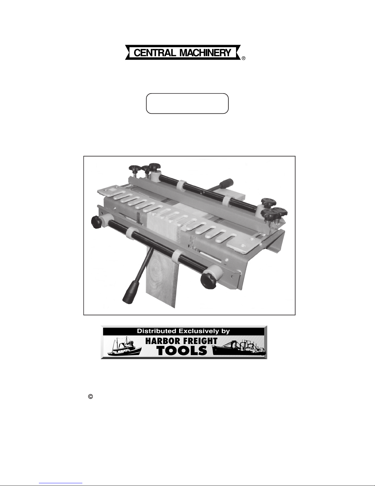
12” DOVETAIL JOINT FIXTURE
®
Model 34102
ASSEMBLY AND OPERATING INSTRUCTIONS
3491 Mission Oaks Blvd., Camarillo, CA 93011
Visit our Web site at: http://www.harborfreight.com
Copyright 2002 by Harbor F reight Tools®. All rights reserved. No portion of this
manual or any artwork contained herein may be reproduced in any shape or form
without the express written consent of Harbor Freight Tools.
For technical questions, please call 1-800-444-3353.
(Wood stock not included.)
Rev 12/02
Page 2

PRODUCT SPECIFICATIONS
Item Description
Dovetail Jig Style
Maximum Stock Thickness Capacity 1-1/4” Thick
Top Width Range 5-1/2” To 12”
Front Width Range 5-13/16” To 10- 7/8”
Comb Size 1/2”
Eccentric Fixing Allowance 5/16”
Stop Pin Allowance 1”
Dimensions 10-1/4” H x 17” W x 15-3/4” L
Weight 20.90 Pounds
For Cutting
Only. Includes ½” Template
“Half-Blind”
Jigs
This Dovetail Joint Fixture is designed to be used with 1/4” shank, 1/2”, 14 degree dovetail
bits only. Note: The bit should protrude approximately 1/2” below the Router base plate,
but may need minor adjustment.
SAVE THIS MANU AL
You will need this manual for the safety warnings and precautions, assembly,
operating, inspection, maintenance and cleaning procedures, parts list and assembly diagram. Keep your invoice with this manual. Write the invoice number
on the inside of the front cover. Keep this manual and invoice in a safe and dry
place for future reference.
GENERAL SAFETY WARNINGS AND PRECAUTIONS
1. KEEP WORK AREA CLEAN AND DRY. Cluttered, damp, or wet work areas
invite injuries.
2. KEEP CHILDREN AWAY FROM WORK AREA. Do not allow children to handle
this product.
3. STORE IDLE EQUIPMENT. When not in use, tools and equipment should be
stored in a dry location to inhibit rust. Always lock up tools and equipment, and
keep out of reach of children.
4. DO NOT USE THIS PRODUCT IF UNDER THE INFLUENCE OF ALCOHOL OR
DRUGS. Read warning labels on prescriptions to determine if your judgement or
reflexes are impaired while taking drugs. If there is any doubt, do not attempt to
use this product.
5. USE EYE AND BREATHING PROTECTION. Wear ANSI approved safety impact
eye goggles and an ANSI approved dust mask or respirator when using this
product. ANSI approved safety impact eye goggles, dust masks, and respirators
are available from Harbor Freight Tools.
SKU 34102 PAGE 2 REV 02/05
Page 3

6. DRESS SAFELY. Do not wear loose clothing or jewelry, as they can become
caught in moving parts. Wear a protective hair cover ing to prevent long hair from
becoming caught in moving parts. If wearing a long-sleeve shirt, roll sleeves up
above elbows.
7. DO NOT OVERREACH. Keep proper footing and balance at all times to prevent
tripping, falling, back injury, etcetera.
8. INDUSTRIAL APPLICATIONS MUST FOLLOW OSHA REQUIREMENT.
9. STAY ALERT. Watch what you are doing at all times. Use common sense. Do
not use this product when you are tired or distracted from the job at hand.
10. CHECK FOR DAMAGED PARTS. Before using this product, carefully check that
it will operate properly and perform its intended function. Check for damaged
parts and any other conditions that may affect the operation of this product.
Replace or repair damaged or worn parts immediately.
11. REPLACEMENT PARTS AND ACCESSORIES: When ser vicing, use only identi-
cal replacement parts. Only use accessories intended for use with this product.
Approved accessories are available from Harbor Freight Tools.
12. MAINT AIN THIS PRODUCT WITH CARE. Keep this product clean and dry for
better and safer performance.
13. MAINTENANCE: For your safety, service and maintenance should be performed
regularly by a qualified technician.
14. USE THE RIGHT TOOL FOR THE JOB. Do not attempt to force a small tool or
attachment to do the work of a larger industrial tool. There are certain applications for which this tool was designed. It will do the job better and more safely at
the rate for which it was intended. Do not modify this tool, and do not use this
tool for a purpose for which it was not intended.
15. WARNING: The warnings, precautions, and instructions discussed in this manual
cannot cover all possible conditions and situations that may occur. The operator
must understand that common sense and caution are factors, which cannot be
built into this product, but must be supplied by the operator.
SPECIFIC PRODUCT WARNINGS AND PRECAUTIONS
1. USE THE PROPER DOVETAIL BIT (not included) FOR YOUR ROUTER. Do
not use any Bit larger than 1/2”, or damage to the Comb Table (part #18) will
result. Adjust the Bit so that it will not come in contact with the Comb Table or
Working Table (part #1).
SKU 34102 PAGE 3
Page 4

2. WHEN CUTTING LARGE WORKPIECES, MAKE SURE THEY ARE
PROPERLY SUPPORTED.
3. MAINTAIN A SAFE WORKING ENVIRONMENT. Keep the work area well lit.
Make sure there is adequate surrounding workspace. Always keep the work
area free of obstructions, grease, oil, trash, and other debris.
4. WARNING: Some dust created by power sanding, sawing, grinding, drilling, and
other construction activities, contain chemicals known (to the State of California)
to cause cancer, birth defects or other reproductive harm. Some examples of
these chemicals are: lead from lead-based paints, crystalline silica from bricks
and cement or other masonry products, arsenic and chromium from chemically
treated lumber. Your risk from these exposures varies, depending on how often
you do this type of work. To reduce your exposure to these chemicals: work in a
well ventilated area, and work with approved safety equipment, such as those
dust masks that are specially designed to filter out microscopic particles.
(California Health & Safety Code 25249.5, et seq.)
UNPACKING
When unpacking, check to make sure all the parts shown on the Parts List on page 13
are included. If any parts are missing or broken, please call Harbor Freight Tools at the
number shown on the cover of this manual as soon as possible.
PRODUCT OVERVIEW
1. The Model 34102 Dovetail Joint Fixture allows you to create strong, precision
cut, “Half-Blind” dovetails. Half-Blind dovetails are visible only from one side,
and commonly used for drawer joinery when you do not want the end grain of the
tails to show in the drawer front. This particular Dovetail Joint Fixture holds both
pieces of wood stock at the same time, and allows you to make both the male
and female cuts (pins and tails) at the same time.
ASSEMBLY INSTRUCTIONS
NOTE: For additional references to the parts listed below, refer to the Assembly
Diagram on page 13.
To Assemble The Dovetail Joint Fixture:
1. Screw the two Knobs (part #12) onto the two Eccentric Rods (part #13). Then,
screw an Eccentric Rod onto each of the two Rotary Rods (part #11).
(See Figure A, next page.)
SKU 34102 PAGE 4
Page 5

ROTARY ROD (#11)
ROTARY ROD (#11)
ECCENTRIC ROD (#13)
KNOB (#12)
WOOD STOCK
ECCENTRIC ROD (#13)
WOOD STOCK
KNOB (#12)
WORKING TABLE (#1)
ROD FIXER (#23)
FIGURE A
To Mount The Dovetail Joint Fixture On A Workbench:
1. CAUTION: Make sure the Dovetail Joint Fixture is mounted on a flat, level,
sturdy, workbench capable of supporting the weight of the Dovetail Joint Fixture,
workpieces, and tools.
2. NOTE: It is necessary to mount the Dovetail Joint Fixture on the front edge of
the workbench, so that the front tab of the Working Table (par t #1) rests against
the vertical edge of the workbench. (See Figure B, next page.)
3. To mount the Dovetail Joint Fixture, use the two mounting holes located at each
end of the Wor k Table (part #1). (See Figure B.)
4. Position the Dovetail Joint Fixture at the desired location on the workbench.
Mark and drill four 3/16” holes in the workbench, using the two mounting holes at
each end of the Dovetail Joint Fixture as a template. Then secure the Dovetail
Joint Fixture to the workbench, using four wood screws (not included).
(See Figure B.)
SKU 34102 PAGE 5
Page 6

WOOD SCREW
(NOT INCLUDED)
FIGURE B
END VIEW
WOOD SCREW
(NOT INCLUDED)
VERTICAL EDGE
OF WORKBENCH
OPERATING INSTRUCTIONS
Wood Stock Placement:
1. Loosen the four Bolts (part #3) enough to allow the horizontal and vertical Stop
Pins (part #19) to move. Then, spread the Stop Pins wider than the width of the
two pieces of wood stock. (See Figure C, next page.)
2. Slightly loosen the front and rear Fixing Screws “B” (part #7), and pull up on the
front and rear Eccentric Rods (part #13). (See Figure C.)
3. Insert the wood stock (from 5-1/2” to 12” wide) horizontally from the back
between the rear Bracket Frame (part #16), Comb Table (part #18), and Working
Table (part #1). (See Figure C.)
4. Adjust the horizontal wood stock so that its forward edge is flush with the forward
vertical edge of the Working Table. (See Figure C.)
SKU 34102 PAGE 6
Page 7

FIXING SCREW “A” (#6)
FIXING SCREW “B” (#7)
BRACKET
FRAME (#16)
COMB T ABLE (#18)
BOLT (#3)
STOP PIN
(#19)
FIXING SCREW “B” (#7)
ECCENTRIC ROD (#13)
SPACING SCREW (#8)
WOOD STOCK
ECCENTRIC ROD (#13)
WOOD STOCK
FIXING SCREW “B” (#7)
SPACING SCREW (#8)
FIXING
SCREW “A” (#6)
FIXING
SCREW “B”
(#7)
BOLT (#3)
STOP
PIN (#19)
BOLT (#3)
STOP PIN (#19)
WORKING TABLE (#1)
BRACKET FRAME (#16)
FIGURE C
5. Tighten the two rear Fixing Screws “B” (part #7), and pull down on the rear
Eccentric Rod (part #13) to clamp the horizontal wood stock in place.
(See Figure D, next page.)
6. Insert the second piece of wood stock (from 5-13/16” to 10-7/8” wide) vertically
from below, between the front Bracket Frame (part #16) and the vertical edge of
the Working Table (part #1). NOTE: The top edges of the two wor kpieces should
be flush. (See Figure C.)
7. IMPORTANT: The vertical wood stock should be positioned offset to the left of
the horizontal wood stock by the width of one Comb on the Comb Table (part
#18). (See Figure C.)
8. If necessary, adjust the forward/backward position of the Comb Table (part #18)
until the tips of the Combs are approximately 5/32” clear of the vertical wood
stock’s edge. To do so, slightly loosen the two Fixing Screws “A”. Move the
Comb Table inward or outward until it is properly positioned. Then, retighten the
Fixing Screws “A”. (See Figure D.)
9. Adjust the width of the four Stop Pins (part #19) so that they touch the two pieces
SKU 34102 PAGE 7
Page 8

FIXING SCREW “A” (#6)
FIXING SCREW “B” (#7)
ECCENTRIC ROD (#13)
COMB T ABLE (#18)
BOLT (#3)
STOP PIN (#19)
FIXING SCREW “B” (#7)
ECCENTRIC ROD (#13)
FIXING SCREW “B” (#7)
WOOD STOCK
WOOD STOCK
FIXING
SCREW “A” (#6)
FIXING
SCREW “B” (#7)
BOLT (#3)
STOP PIN (#19)
BOLT (#3)
STOP PIN (#19)
FIGURE D
of wood stock on their sides. Then, retighten the four Bolts (part #3) to secure
the Stop Pins in place. (See Figure D.)
10. When the vertical wood stock is in the proper position tighten the two front Fixing
Screws “B”, and clamp the wood stock in place by pulling down on the front
Eccentric Rod (part #13). (See Figure D.)
11. If necessary, adjust the forward/backward position of the Comb Table (par t #18)
until the tips of the Combs are approximately 5/32” clear of the vertical wood
stock’s edge. To do so, slightly loosen the two Fixing Screws “A”. Move the
Comb Table inward or outward until it is properly positioned. Then, retighten the
Fixing Screws “A”. (See Figure D.)
Using Router Guide Bushings And Bearing Guides:
1. Router guide bushings (not included) are attached to the base of the Router (not
included), and used for limiting the
depth
of cut between the Combs of the Comb
Table (part #18). The guide bushing should protrude 1/8” to 3/16” below the base
of the router and have a 7/16” outside diameter (See Figure E, next page.)
2. This Dovetail Joint Fixture is designed to be used with 1/4” shank, 1/2”, 14 degree
dovetail bits only. The bit should protrude approximately 1/2” below the Router
base plate, but may need minor adjustment.
SKU 34102 PAGE 8 REV 02/05
Page 9

Template Size Bit Size Bushing Size Pin Width
Base of Router
1/2” 1/2” 1/2” 5/8”
7/16” 1/2” 7/16” 1/2”
Guide Bushing
1/8” to 3/16”
1/2”
Dovetail
Bit
FIGURE E
3. This Dov etail Joint Fixture comes with a 1/2” template. Figure F shows the pin
widths produced by different siz ed templates. Optional dovetail templates
availab le from Harbor Freight Tools include: Item 38808 9/16” template,
Item 38809 7/16” template, and Item 38810 1/2” template.
4. If you do not use a Router Guide Collar, the following Router Ball Bearing Guides
included) are also suited to work with the Dovetail Joint Fixture.
ROU TER B ALL BE AR ING GU IDES (not included)
Degree
Side
14° 0.587” 0.472” 0.25” 1/2” 1/2”
14° 0.587” 0.472” 0.25” 1/2” 9/16”
14° 0.457” 0.472” 0.25” 3/8” 7/16”
Cu ttin g
Depth
Cu tti ng
Length
Cutting The Dovetails:
9/16” 1/2” 9/16” 3/4”
Tail
FIGURE F
Shank Bearing
O.D.
Comb
Pin
Pin Width
Size
Pin
Depth
1. CAUTION: Never allow the Router Bit to come in contact with either the Comb
Table (part #18) or the Wor king Table (part #1). Use the proper Router Bit, and
properly adjusted Router Guide Collar or Router Ball Bearing Guide. Do not use
any Router Bit larger than 1/2” diameter, or damage to the Comb Table will occur.
2. Follow the instructions in your Router manual to properly set up the Router and
its accessories to cut dovetails.
3. Place the Router on the Comb Table (part #18). Do not allow the Router Bit to
contact either pieces of wood stock. Then, turn on the Router. (See Figure D.)
4. Guide the Router Bit in and out between the Combs of the Comb Table (part
#18). Make sure to cut the two pieces of wood stock to the full depth, but do not
cut into the Comb Table or the Wor king Table (par t #1). (See Figure D.)
5. When the dovetails have been completely cut, tur n off and remove the Router.
SKU 34102 PAGE 9 REV 10/13 REV 02/05
Page 10

10 7/8”
FLUSH DOVETAIL JOINT
FIGURE G
To Cut A Flush Dovetail Joint:
1. Loosen the four Bolts (part #3), and adjust the four Stop Pins (part #19) so they
are offset by the 1/2” Comb being used (1/2” and 90 degrees to the front edge of
the Bracket Frame (part #16). Then, retighten the four Bolts.
(See Figures C, D, and G.)
2. Measure, cut the wood stocks to the desired size, and lay them out. Then, mark
each wood stock “front,” or “left,” or “back,” or “r ight.” Also, number each end of
each wood stock. (See Figure G.)
3. Measure and cut two test wood stocks the same size as the actual wood stocks.
Mark the two test wood stocks as instructed in Step #2. Then, insert the two test
wood stocks in the Dovetail Joint Fixture to test, and make the corner dovetail
cuts as shown. (See Figure G.)
4. Attach a 1/2” Router Bit and 1/2” Guide Collar to the Router, and set the Bit to
extend 23/32” below the base plate of the Router.
5. Place the Router on the Comb Table (part #18) and rout a groove across the
edge of the left side of the test wood stock, moving from right to left and touching
the tip of each Comb as you move across. Without lifting the Router, completely
rout the test wood stocks.
SKU 34102 PAGE 10 REV 10/04
Page 11

6. Remove both test wood stocks from the Dovetail Joint Fixture to test for proper
fit. If the dovetail joint fits properly, no further adjustment is necessary. If the joint
is too loose, increase the distance from the base plate on the Router to the
bottom of the Router Bit 1/64”. If the joint is too tight, decrease the distance
1/64”.
7. Once the Dovetail Joint Fixture is properly adjusted, the actual wood stocks may
be cut. First, cut the front and left side wood stocks on the left side of the
Dovetail Joint Fixture. Then follow the same procedure, but use the right side of
the Dovetail Joint Fixture to cut the other ends of the front wood stock and right
side wood stock.
To Cut A Flush-Offset Dovetail Joint:
1. When cutting the front wood stock for the flush-offset joint, add 3/4” to the length
of the wood stock. Make sure the thickness of the wood stock is a minimum of
7/8” to allow for a 3/8” wide by 1/2” deep rabbet (cut prior to the dovetail procedure) on both ends. (See Figure H.)
2. Proceed the same as when cutting a flush joint, except loosen the two Fixing
Screws “B” (part #7) and move the Bracket Frame (part #16) 3/8” toward the
back of the Dovetail Joint Fixture to allow for the 3/8” offset. Then, retighten the
two Fixing Screws “B.” (See Figure D.)
SKU 34101 PAGE 11
FIGURE H
Page 12

To Cut A Rabbeted Dovetail Joint:
1. When cutting the front wood stock for the rabbeted joint, add 3/4” to the length
and 3/4” to the width. Make sure the thickness of the wood stock is a minimum
of 7/8” to allow for a 3/8” wide by 1/2” deep rabbet all around. (This should be
cut on the inside-front wood stock prior to the dovetail procedure.)
(See Figure H.)
2. Proceed the same as when cutting an offset joint, but adjust the two front Stop
Pins (part #19) for the front wood stock. The Stop Pins should be set so the
offset is 1/8”. (See Figures D, and H.)
INSPECTION, MAINTENANCE, AND CLEANING
1. BEFORE EACH USE, inspect the general condition of the Dovetail Joint Fixture.
Check for loose screws, misalignment or binding of moving parts, cracked or
broken parts, loose and improper mounting on workbench, and any other condition that may affect its safe operation. If a problem with the Dovetail Joint Fixture
occurs, have the problem corrected before further use.
Do not use damaged equipment.
2. DAILY: With a soft brush, cloth, or vacuum, remov e all sawdust and debris from the
Dovetail Joint Fixture. You may wipe with a damp cloth, using a mild detergent or
mild solvent.
PLEASE READ THE FOLLOWING CAREFULLY
THE MANUFACTURER AND/OR DISTRIBUTOR HAS PROVIDED THE PARTS LIST
AND ASSEMBLY DIAGRAM IN THIS MANUAL AS A REFERENCE TOOL ONLY. NEITHER THE MANUFACTURER OR DISTRIBUTOR MAKES ANY REPRESENTATION
OR WARRANTY OF ANY KIND TO THE BUYER THAT HE OR SHE IS QUALIFIED TO
MAKE ANY REPAIRS TO THE PRODUCT, OR THAT HE OR SHE IS QUALIFIED TO
REPLACE ANY PARTS OF THE PRODUCT. IN FACT, THE MANUFACTUER AND/OR
DISTRIBUTOR EXPRESSLY STATES THAT ALL REPAIRS AND PARTS REPLACEMENTS SHOULD BE UNDERTAKEN BY CERTIFIED AND LICENSED TECHNICIANS,
AND NOT BY THE BUYER. THE BUYER ASSUMES ALL RISK AND LIABILITY ARISING OUT OF HIS OR HER REPAIRS TO THE ORIGINAL PRODUCT OR REPLACEMENT PARTS THERETO, OR ARISING OUT OF HIS OR HER INSTALLATION OF
REPLACEMENT PARTS THERETO.
SKU 34102 PAGE 12
Page 13

PARTS LIST
#
#
Part
1 Working Table 1 13 Eccentric Rod 2
2 Washer 8 14 Screw 4
3 Bolt 4 15 Spring 4
4 Nut 8 16 Bracket Frame 1
5 Side Brace 2 17 Screw 4
6 Fixing Screw “A” 2 18 Comb Table 1
7 Fixing Screw “B” 4 19 Stop Pin 4
8 Spacing Screw 4 20 Adjusting Nut 2
9 Bar Fixing Stand 4 21 Support 2
10 Eccentric Wheel 4 22 Screw 4
11 Rotary Rod 2 23 Rod Fixer 2
12 Knob 2
Description Qty. Part
Description Qty.
ASSEMBLY DIAGRAM
NOTE: Some parts are listed and shown for illustration purposes only, and are not
available individually as replacement parts.
SKU 34102 PAGE 13
 Loading...