

Page 1

7” x 10” Mini Lathe
®
Model 33684
Assembly and Operating Instructions
3491 Mission Oaks Blvd., Camarillo, CA 9301 1
Copyright 2000 by Harbor Freight T ools®. All rights reserved. No portion of this
manual or any artwork contained herein may be reproduced in any shape or form
without the express written consent of Harbor Freight T ools.
For technical questions and replacement parts, please call 1-800-444-33534.
Page 2

Important Safety Instructions
READ ALL INSTRUCTIONS AND WARNINGS BEFORE USING THIS T OOL.
Operator
COMMON SENSE AND CAUTION ARE FACTORS WHICH CANNOT BE BUILT INTO
ANY PRODUCT . THESE F ACTORS MUST BE SUPPLIED BY THE OPERATOR. PLEASE
REMEMBER:
1. When using electric tools, machines or
equipment, basic safety precautions should
always be followed to reduce the risk of fire,
electric shock, and personal injury .
2. Keep work area clean. Cluttered areas
invite injuries.
3. Consider work area conditions. Do not
use machines or power tools in damp, wet,
or poorly lit locations. Do not expose
equipment to rain. Keep work area well lit.
Do not use tools in the presence of flammable gases or liquids.
4. Keep children away. All children should
be kept away from the work area.
5. Guard against electric shock. Prevent
body contact with grounded surfaces such as
pipes, radiators, ranges, and refriderator
enclosures.
6. Stay alert. Never operate equipment if
you are tired.
7. Do not operate the product if under the
influence of alcohol or drugs. Read warning
labels on prescriptions to determine if your
judgment or reflexes might be impaired.
8. Do not wear loose clothing or jewelry as
they can be caught in moving parts.
9. W ear restrictive hair covering to contain
long hair.
10. Use eye and ear protection. Always
wear:
-ANSI approved chemical splash goggles
when working with chemicals.
-ANSI approved impact safety goggles at
other times.
-ANSI approved dust mask or respirator
when working around metal, wood, and
SKU #33684 Page 2
chemical dusts and mists.
-A full face shield if you are producing metal
or wood filings.
11. Keep proper footing and balance at all
times.
12. Do not reach over or across running
machines.
13. Always check that adjusting keys and
wrenches are removed from the tool or
machine work surface before plugging it in.
14. Do not carry any tool with your finger on
either the start button or trigger.
15. When servicing, use only identical replacement parts.
Before Operation
1. Be sure the switch is OFF when not in use
and before plugging in.
2. Do not attempt to use inappropriate
attachments in an attempt to exceed the tool’s
capacity . Approved accessories are available
from Harbor Freight T ools.
3. Check for damaged parts. Before using
any tool, any part that appears damaged
should be carefully checked to determine that
it will operate properly and perform its intended function.
4. Check for alignment and binding of all
moving parts, broken parts or mounting
fixtures and any other condition that may
affect proper operation. Any part that is
damaged should be properly repaired or
replaced by a qualified technician.
5. Do not use the tool if any switch does not
turn off and on properly .
Page 3

Operation
1. Never force the tool or attachment to
do the work of a larger industrial tool. It is
designed to do the job better and more
safely at the rate for which it was intended.
2. Do not carry the tool by its power
cord.
3. Always unplug the cord by the plug.
Never yank the cord out of the wall.
4. Always turn off the machine before
unplugging.
IF THERE IS ANY QUESTION
ABOUT A CONDITION BEING
SAFE OR UNSAFE, DO NOT
OPERA TE THE TOOL!
Check to see if your tool has a two or threeprong plug. If your tool has a two-prong plug,
you may proceed past the next paragraph. If
your tool has a three-prong plug, please continue
reading the following precautions and instructions.
If the tool or machine has a three-prong plug, the
third (round) prong is the ground. Plug this cord
only into a three-prong receptacle. Do not
attempt to defeat the protection the ground wire
provides by cutting off the round prong. Cutting
off the ground will result in a safety hazard and
void the warranty .
Grounding Instructions and
Voltage Warning
Common household current is 110-120 volts.
As long as your tool is rated from 110-120V
there will be no complications using this tool
with household receptacles. NEVER try to
plug a 110-120V tool into a 220-240V circuit
(or vice-versa) or serious complications and
possible serious injury to the operator can
occur. The plugs have different shapes to
prevent this.
____________________________________________________________________________
If a three-prong receptacle is not available, you
may use an adapter, but you must then connect
the green ear on the adapter to the outlet.
Unscrew the center screw of the outlet cover
and put the screw through the green ear. Plug
the adapter’s two prongs into the outlet, and
replace the center screw . Now plug the tool or
machine into the adapter.
DO NOT MODIFY THE PLUG IN ANY
W AY . IF YOU HAVE ANY DOUBT , CALL
A QUALIFIED ELECTRICIAN.
Extension Cords
If your tool is double insulated and has a two-prong plug, you may use either a two or three-prong
extension cord. If your tool has a grounded, three-prong plug, you must use a three-prong extension
cord with three-prong receptacles. Only use rounded jacket extension cords listed by the Underwriters Laboratories (UL). If you are using the tool outdoors, use an extension cord rated for
outdoor use (signified by “W A” on the jacket).
The extension cord must have a minimum wire size depending on the amperage of the tool and the
length of the extension cord. The size is determined by its A WG (American Wire Gauge) rating. The
smaller the gauge, the greater the cable’ s capacity. The amount of cords used does not matter. T otal
length determines the minimum A WG rating. Every cord must meet the A WG rating. Use the chart
below to determine what AWG rating is required for your situation. Cord length is rated in feet.
Harbor Freight T ools can supply UL listed and outdoor rated extension cords in multiple A WG
ratings if needed.
AMP T otal Extension Cord Length In Feet
Rating 25’ 50’ 75’ 100’ 125’ 150’ 175’ 200’
0.0 -10.0 18 18 16 16 14 14 12 12
10.1-13.0 16 16 14 14 14 12 12 12
13.1-15.0 14 14 12 12 12 12 12 --
15.1-18.0 14 12 12 12 12 12 -- --
SKU #33684 Page 3
Page 4

Additional Safety Rules for Mini Lathe
1. Before turning on the motor, make sure
that proper lubrication is included (see page
of this manual).
2. Always dismount the chuck and lathe’ s
face plate by hand. Do not use power tools
to perform these tasks.
3. After the chuck is installed, remove the
wrenches and tools to eliminate the possibility of accident when the lathe is turned
on.
4. Never adjust or fix workpieces or any
rotating parts when the lathe is on. Never
use instruments to measure the workpiece
____________________________________________________________________________
Thank you for choosing a Harbor Fr eight T ools product! For future reference, please
complete the owner’s record below:
Model:_______________ Serial Number:_________________ PurchaseDate:__________
when the lathe is on. Never check the
sharpness of the cutter by using your hand.
5. A void accidents resulting from broken
workpieces. Never use an excessively large
tool cutter to do feeding with a large
workpiece.
6.Never change the gear when the lathe is in
operation.
7. Always keep a safe distance from the lathe
to minimize the risk of being struck by a
broken workpiece.
SAVE THE RECEIPT , W ARRANTY AND THESE INSTRUCTIONS. It is important that you
read the entire manual to become familiar with the unit BEFORE you begin assembly .
____________________________________________________________________________
Technical Specifications
Motor: 3/4 Horsepower
Power Source: 110V, Single Phase
Lathe Specifications:
Drive: Gear and Belt
Swing Over Bed: 7”
Distance Between Centers: 10”
Spindle Bore: 3/4”
Quill Travel: 2”
Cross Slide Travel: 2 3/4”
Cross Slide Swing: 4 1/2”
W ork T olerance: .005”
Bed Dimensions: 15 7/8” long, 3 1/4” wide
Saddle Travel: 6 7/8”
Compound Travel: 2 7/8”
SKU #33684 Page 4
Page 5
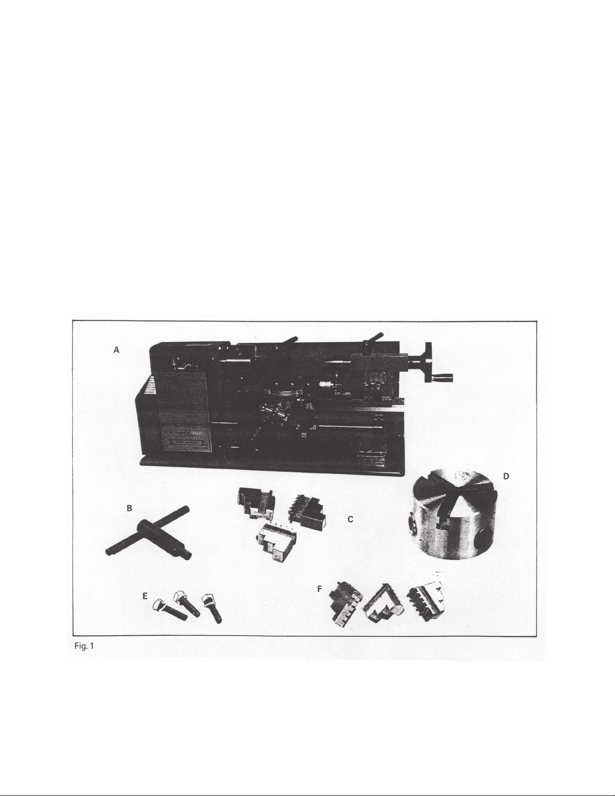
Unpacking
Carefully unpack the Mini Lathe and check all items. Figure 1 below shows all the contents of the
carton. Do not discard any packing material until the Mini Lathe is fully assembled and operational.
If any parts are missing or broken, please call Harbor Freight T ools at 1-800-444-3353. Be sure
you have all parts described in the parts listing on page .
Identification of Main Components
A. Lathe B. Chuck Key C. External Jaws
D. Chuck E. Chuck Set Screws F . Internal Jaws
SKU #33684 Page 5
Page 6
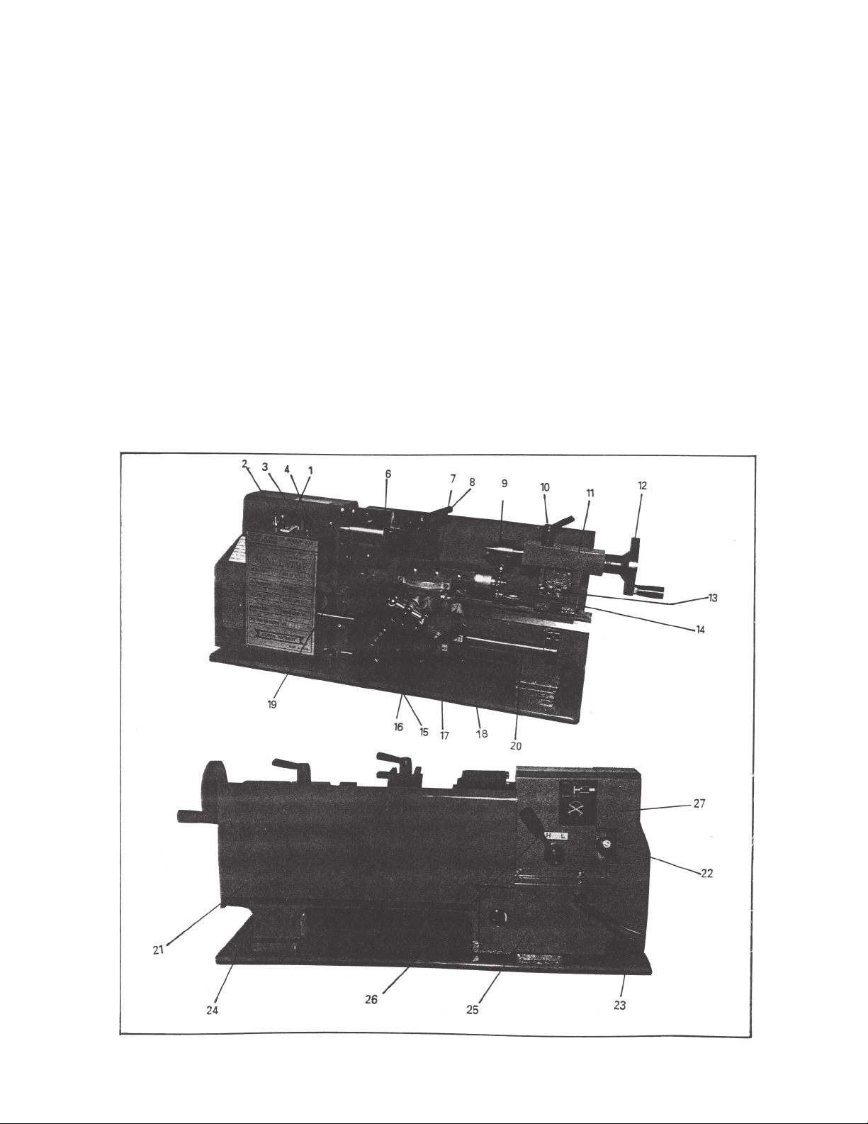
Mini Lathe Features
1. Power Switch
2. Power lamp
3. Fuse
4. Speed Control Knob
6. Chuck
7. Compound Rest
8. T ool Post
9. Fixed Center
10.T ailstock Quill Fix Holder
11. Tailstock
12. T ailstock Quill Adjust Handwheel
13. T ailstock Set Screw
14. Compound Rest Crank
1.15. Feeding Control Wheel
16. Cross Feeding Crank
17. Automatic Feeding Handle
18. Thread Dial Indicator
19. Bed Way
20. Lead Screw
21. Rear Splash Guard
22. Feeding Direction Selector
23. Power Cord
24. Chip Tray
25. Motor Cover
26. H/L Gear Shift Lever
27. End Cover
SKU #33684 Page 6
Page 7

Adjusting the Mini Lathe
1. Clean off the protective grease on the Mini Lathe.
2. Check to see that the three set screws on the chuck are tight.
3. Turn the chuck by hand and check that it rotates freely .
4. Move the Feeding Direction Selector (located on the back of lathe) to the middle.
5. Make sure the Switch (#1 in figure 4 below) is at the OFF position.
WARNING: ADJUST THE SPEED CONTROL KNOB (#4) BY TURNING IT TO
ZERO. BEFORE TURNING ON THE MINI LA THE EACH TIME IT IS TO BE USED,
THIS SPEED CONTROL KNOB MUST BE A T ZERO.
6. Plug in the electrical cord and turn the Switch to the ON position and run the lathe for 3 minutes.
When the lathe is on, the Power Lamp (#2) will remain on. Check to see that the lathe operates
normally .
7. Check the Compound Rest Crank and the Cross Feeding Crank to see that they work properly .
If the cranks are too tight or too loose, turn the adjusting screws located at both sides (see figure 5
below).
WARNING: THE MINI LA THE MUST BE COMPLETEL Y STOPPED BEFORE
CHANGING FOR W ARD/REVERSE DIRECTION.
Replacement of Chuck
When replaceing the chuck, place a cloth or a piece of wood on the bedway at the bottom of the
chuck. This step will help avoid damage to the bedway caused by carelessly dropping the chuck.
T o replace the chuck, loosed the 3 set screws as shown in figure 6 below .
Rev 01/99SKU #33684 Page 7
Page 8

Replacement of Jaws
There are two types of jaws: the internal
jaws and external jaws. Please note that the
number of jaws fit with the number inside the
chuck’s groove. Do not mix them together .
When you are going to mount the jaws,
mount them in ascending order. When they
are taken out, make sure to take them out in
descending order (3-2-1) one by one. After
you finish this procedure, rotate the jaws to
the smallest diameter and check that the three
jaws are well fitted (see figure 7).
If the jaws do not fit well together, you will need to
reassemble them again.
When mounting a workpiece, it is recommended
that all three jaws are loosened at the same time.
This will protectthe threads inside.
Compound Rest Adjustment
T o adjust the compound rest, loosen the two
screws as shown in figure 8 (A). After adjusting
to the required angle, tighten the screws.
Tailstock Rest Adjustment
T o change position or replace the tailstock, loosen the nut as shown in (A) of figure 9.
Replacement of Carbon Brushes
T o replace, remove brush covers on the motor cover (A) in figure 10-A, and the right bottom side of
speed controller as shown in (B) of figure 10-B.
SKU #33684 Page 8
Page 9

Tool Post Adjustment
Loosen the lever shown in (B) of figure 11,
the adjust the tool post position. Once the
adjustment is made, re-tighten the lever. To
replace the work cutter, loosen the screws
(A) with the allen wrench provided.
Automatic Feeding
Adjust the feeding direction selector to the
direction you desire. Press down the handle
(A) in figure 12, and continue with the
automatic feeding procedure. When
feeding, never try to change the feeding
direction.
Threading
Select the feeding direction selector to the
thread direction desired. Then press down
handle (A) in figure 12 by matching the right
calibrations on the thread dial indicator (B)
and continue with the automatic threading
procedure. When threading, never try to
change the direction.
Operation
1. Use the chuck to hold the workpiece
firmly (figure 13 below). Then, use the rolling
center to fix the other end. If you change the
rolling center to drilling chuck you start your
drilling immediately .
SKU #33684 Page 9
2. Use the chuck to hold the workpiece firmly
and cutter to start lathe’s face cutting (figure
14). The edge of the cutter must be at the
same height as the center.
Page 10

3. By changing the tool post angle and adjusting the compound rest, you can do internal cutting
(figure 15).
4. After adjusting the angle of the compound rest, you can do bevel cutting (figure 16).
Set-Up Instructions for Threading Gears
By changing the gear set-up it is possible to cut any thread size. The factory set-up for Mini Lathe
gears is as follows (see illustration below):
A A
Position A= 20T
B
C C B
D
D
T o change the thread size, use the gear box settings shown on the table on the next page.
Position B= 80T
Position C= 20T
Position D= 80T
SKU #33684 Page 10
Page 11

Gear Settings for Various Thread Sizes
Threads Stud Gear Box Threads Stud Gear Box
Per Inch A B C D Per Inch A B C D
12 40 30 38 20 50 60 57
13 40 65 60 30 40 20 50
14 40 35 44 20 55
16 40 40 48 20 60
18 40 45 52 20 65
19 40 50 60 57 56 20 35 30 60
20 40 50 64 20 40 20 40
22 40 55 72 20 45 20 40
24 40 60 76 20 50 30 57
26 40 65 80 20 50 20 40
28 20 35 88 20 55 20 40
32 20 40 96 20 60 20 40
36 20 45 104 20 65 20 40
Example: T o cut 12 threads per inch (see illustration below), use 40T in position A, 30T in
position D, and put any other gear is position B to connect A and D.
A
A
B B
D D
A
B C C B
D D
Example: T o cut 38 threads per inch (see illustration above), use 20T in position
A, 57T in position D, 50T in position B, and 60T in position C.
A
SKU #33684 Page 11
Page 12

SKU #33684 Page 13
Page 13

SKU #33684 Page 14
Page 14

Parts Diagram
SKU #33684 Page 15
Page 15

Additional Set-Up Instructions for Threading Gears
When the lathe is ON and the Spindle is revolving, the threaded bar and the Thread Dial Indicator
will also be revolving (see below).
Thread Dial Indicator
Indicator Housing
T op View
Thread Indicator Housing
Insure that the Alignment Mark is lined up with the
Thread Dial Indicator before operation.
Move the cutting blade to the proper position, and adjust theThread Dial Indicator to the desired
mark. Pull down the Handle and the Mini Lathe starts threading automatically .
Remember: After thread cutting operation is complete, change back to the factory set-up gear
setting:
Position A= 20T
Position B= 80T
Position C= 20T
Position D= 80T
SKU #33684 Page 12
#33684 Page 12
Page 16

SKU #33684 Page 16
Page 17

P ACKING LIST
No. Description Qty Part No.
1 7” x 10” Mini Lathe 1 piece
2 Chuck external jaws 3 piece
3 Chueck Key 1 piece
4 Fuse 5A 1 piece
5 Gear Z: 30, 35, 40, 40, 45, 50, 55, 57, 60, 65 10 pieces
6 Double head wrench 8-10, 14-17 2 pieces
7 Inside six horn wrench S: 3, 4, 5, 6 4 pieces
8 Oil can 1 piece
9 Center MT : 2 1 piece 143
10 Rubber 4 pieces 125
11 Knob 2 pieces 85
12 Instruction Manual 1 copy
13 Wiring Diagram of Control Circuit 1 copy
14 Warranty Document 1 copy
SKU #33684 Page 17
Page 18

SCHEMA TIC DIAGRAM
Fuse
Switch 2
Potentiometer
Switch 1
Motor
110V/60Hz
SKU #33684 Page 18
REV 08/04
 Loading...