

Page 1

RABBETING JOINTER
Model
32966
®
Brought To You By Augusta Flint
8” - WITH STAND
ASSEMBLY AND OPERATION INSTRUCTIONS
Due to continuing improvements, actual product may differ slightly from the product described herein.
3491 Mission Oaks Blvd., Camarillo, CA 93011
Visit our website at: http://www.harborfreight.com
TO PREVENT SERIOUS INJURY, READ AND UNDERSTAND
ALL WARNINGS AND INSTRUCTIONS BEFORE USE.
Copyright© 2007 by Harbor Freight Tools®. All rights reserved. No portion of this
manual or any artwork contained herein may be reproduced in any shape or form
without the express written consent of Harbor Freight Tools.
Page 2

SPECIFICATIONS
Brought To You By Augusta Flint
115 VAC / 60 Hz / 2 HP, 3450 RPM Motor
4600 RPM Cutter Head Speed
Electrical
Requirements
Infeed Table 23-1/4” L x 9-3/8” W @ end, 9-1/4” W @ blade end
Outfeed Table 27-1/4” L x 8-3/4” W
Rabbeting Ledge 9-3/4” L x 3” W
Machine Size 66” x 25-1/2” x 37-1/4”
Depth of Cut 1/2” Maximum (In 1/64” Increments)
Fence Size 34-1/2” L x 3-3/4” H
Table Tilt Capacity 45 Degrees Left/Right / Positive Stops at 45 & 90 Degrees
Gross Weight 360 Pounds
Start-Up Amps = 16.0 / No Load Amps = 7.0
Power Cord Type: 16 Gauge / 62” Long
Power Plug Type: 3-Prong / Grounded
Features Overload Protection & Lock-On Switch
SAVE THIS MANUAL
You will need this manual for the safety warnings and precautions, assembly, operating, inspection, maintenance and cleaning procedures, parts list and assembly diagram.
Keep your invoice with this manual. Write the invoice number on the inside of the front
cover. Write the product’s serial number in the back of the manual near the assembly diagram, or write month and year of purchase if product has no number. Keep this manual
and invoice in a safe and dry place for future reference.
1.
2.
GENERAL SAFETY RULES
WARNING!
READ AND UNDERSTAND ALL INSTRUCTIONS
Failure to follow all instructions listed below may result in
electric shock, fire, and/or serious injury.
SAVE THESE INSTRUCTIONS
WORK AREA
Keep your work area clean and well lit. Cluttered and dark areas invite acci-
dents.
Do not operate power tools in explosive atmospheres, such as in the pres-
ence of flammable liquids, gases, or dust. Power tools create sparks which may
ignite the dust or fumes.
For technical questions, please call 1-800-444-3353.
Page 2SKU 32966
Page 3

3.
Brought To You By Augusta Flint
Keep bystanders, children, and visitors away while operating a power tool.
Distractions can cause you to lose control. Protect others in the work area from
debris such as chips and sparks. Provide barriers or shields as needed. Children
should never be allowed in the work area.
PERSONAL SAFETY
1.
2.
3.
4.
5.
Stay alert. Watch what you are doing, and use common sense when operat-
ing a power tool. Do not use a power tool while tired or under the influence
of drugs, alcohol, or medication. A moment of inattention while operating power
tools may result in serious personal injury.
Dress properly. Do not wear loose clothing or jewelry. Contain long hair.
Keep your hair, clothing, and gloves away from moving parts. Loose clothes,
jewelry, or long hair can be caught in moving parts.
Remove adjusting keys or wrenches before turning the power tool on. A
wrench or a key that is left attached to a rotating part of the power tool may result
in personal injury.
Do not overreach. Keep proper footing and balance at all times. Proper footing
and balance enables better control of the power tool in unexpected situations.
Use safety equipment. Always wear ANSI-approved safety impact
goggles when using this product. Dust mask or respirator,
nonskid safety shoes, hard hat, or hearing protection must be used for
appropriate conditions. Always wear ANSI-approved safety goggles and
a dust mask/respirator when using or performing maintenance on this tool.
1.
2.
3.
4.
TOOL USE AND CARE
Do not force the tool. Use the correct tool for your application. The correct
tool will do the job better and safer at the rate for which it is designed. Do not force
the tool and do not use the tool for a purpose for which it is not intended.
Do not use the Rabbeting Jointer if its Power Switch does not turn it on or
off. Any equipment that cannot be controlled with the Power Switch is dangerous
and must be replaced.
Turn off the Power Switch and disconnect the Power Cord before making any
adjustments, changing accessories, or storing the Rabbeting Jointer. Such
preventive safety measures reduce the risk of starting the tool accidentally. Always
turn off the Power Switch and disconnect the Power Cord before performing
any inspection, maintenance, or cleaning procedures.
Store idle tools out of reach of children and other untrained persons. Tools
are dangerous in the hands of untrained users.
For technical questions, please call 1-800-444-3353.
Page 3SKU 32966
Page 4

5.
Brought To You By Augusta Flint
Maintain tools with care. Keep the Rabbeting Jointer clean. Properly main-
tained tools are less likely to malfunction and are easier to control. Do not use a
damaged tool. Tag damaged tools “Do not use” until repaired.
6.
7.
1.
2.
3.
Check for misalignment or binding of moving parts, breakage of parts, and any
other condition that may affect the tool’s operation. If damaged, have the tool
serviced before using. Many accidents are caused by poorly maintained tools.
Use only accessories that are recommended by the manufacturer for your
model. Accessories that may be suitable for one tool may become hazardous
when used on another tool.
SERVICE
Prior to performing service, maintenance, or cleaning procedures, always
make sure the Rabbeting Jointer’s Power Switch is in its “OFF” position and
the Power Cord is disconnected from its electrical outlet.
Tool service must be performed only by qualified repair personnel. Service or
maintenance performed by unqualified personnel could result in a risk of injury.
When servicing a tool, use only identical replacement parts. Follow instruc-
tions in the “Inspection, Maintenance, And Cleaning” section of this manual.
Use of unauthorized parts or failure to follow maintenance instructions may create
a risk of injury.
1.
2.
3.
4.
5.
6.
7.
SPECIFIC SAFETY RULES
Maintain labels and nameplates on the Rabbeting Jointer. These carry im-
portant information. If unreadable or missing, contact Harbor Freight Tools for a
replacement.
Maintain a safe working environment. Make sure there is adequate surrounding
workspace.
Avoid unintentional starting. Make sure you are prepared to begin work before
turning on the Rabbeting Jointer.
Always check all four Knife Set Screws (17) on each of the three Knives (16)
for tightness prior to each use of the Rabbeting Jointer.
People with pacemakers should consult their physician(s) before use. Elec-
tromagnetic fields in close proximity to a heart pacemaker could cause pacemaker
interference or pacemaker failure.
Never leave the Rabbeting Jointer unattended when it is running. Turn off the
tool before leaving the work area.
Always feed the workpiece against the rotation of the Knives (16).
For technical questions, please call 1-800-444-3353.
Page 4SKU 32966
Page 5

8.
Brought To You By Augusta Flint
Make sure to keep hands and fingers away from the Knives (16). Whenever
possible, use “pushsticks” and “pushblocks” (neither included) to feed the workpiece
into the Knives.
9.
10.
11.
12.
13.
14.
Keep all safety guards of the Rabbeting Jointer in place and in proper work-
ing order.
Never stand on the Rabbeting Jointer. Serious injury could occur if the unit is
tipped or the Cutter is accidentally touched.
Make sure the workpiece is free from nails and any other foreign object which
could break or otherwise damage the Knives (16).
Never start the Rabbeting Jointer under a load. Allow the tool to reach full speed
before feeding a workpiece into the Knives (16).
Maintain control of the workpiece at all times. Never allow a workpiece to rest
on the moving Knives (16) without holding on to it.
WARNING! Some dust created by power sanding, sawing, grinding, drilling,
and other construction activities, contains chemicals known [to the State of Califor-
nia] to cause cancer, birth defects or other reproductive harm. Some examples of
these chemicals are:
Lead from lead-based paints
Crystalline silica from bricks and cement or other masonry products
Arsenic and chromium from chemically treated lumber
Your risk from these exposures varies, depending on how often you do this type of
work. To reduce your exposure to these chemicals: work in a well ventilated area,
and work with approved safety equipment, such as those dust masks that are spe-
cially designed to filter out microscopic particles. (California Health & Safety Code
§ 25249.5, et seq.)
MECHANICAL PRECAUTIONS
1.
2.
3.
Prior to performing service, maintenance, or cleaning procedures, always
make sure the Rabbeting Jointer’s Power Switch is in its “OFF” position and
the Power Cord is disconnected from its electrical outlet.
Do not alter or adjust any part of the Rabbeting Jointer that is assembled by
the manufacturer.
Always perform scheduled maintenance completely.
For technical questions, please call 1-800-444-3353.
Page 5SKU 32966
Page 6
NOISE PRECAUTION
Brought To You By Augusta Flint
1.
Prolonged exposure to high noise levels is hazardous to hearing. Always wear
ANSI-approved hearing protection when operating or working around the Rabbeting
Jointer when it is running.
MISCELLANEOUS PRECAUTION
1.
WARNING! The warnings and precautions discussed in this manual cannot
cover all possible conditions and situations that may occur. It must be understood
by the operator that common sense and caution are factors which cannot be built
into this product, but must be supplied by the operator.
GROUNDING
WARNING!
Improperly connecting the grounding wire can result in the risk of electric shock.
Check with a qualified electrician if you are in doubt as to whether the outlet is
properly grounded. Do not modify the power cord plug provided with the tool.
Never remove the grounding prong from the plug. Do not use the tool if the power
cord or plug is damaged. If damaged, have it repaired by a service facility before
use. If the plug will not fit the outlet, have a proper outlet installed by a qualified
electrician.
1.
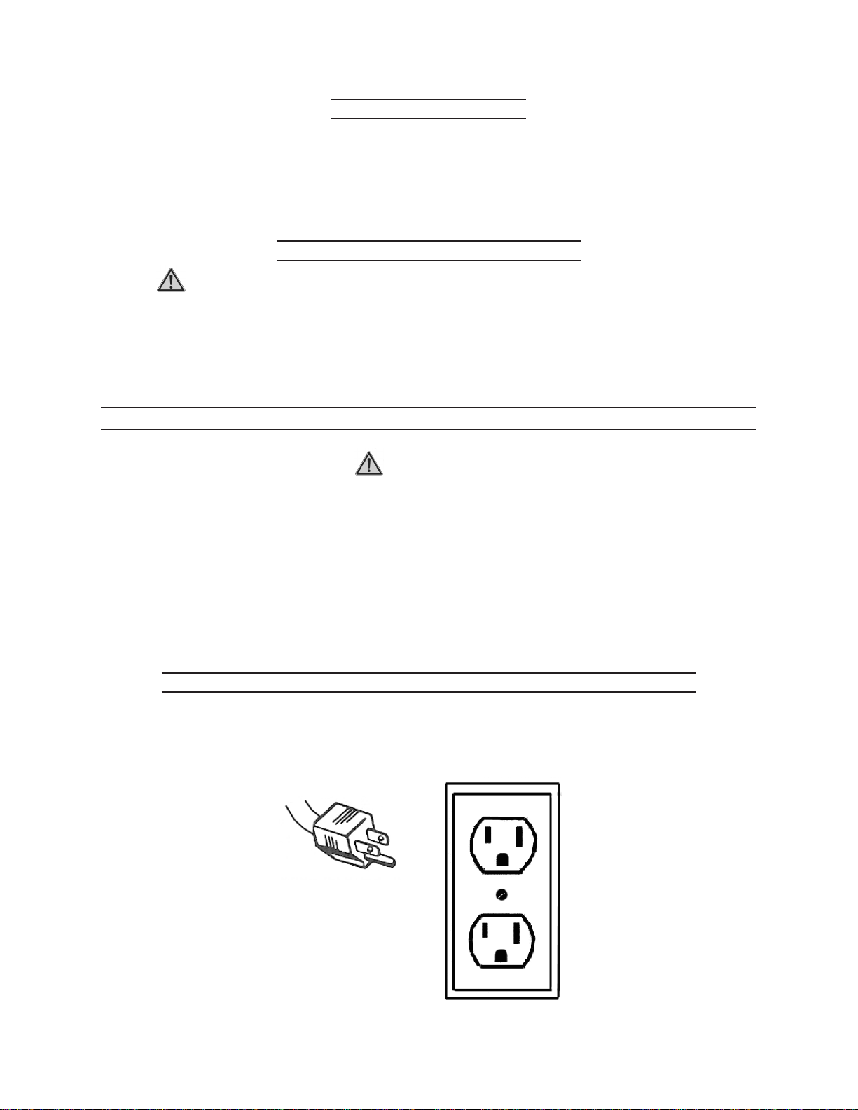
GROUNDED TOOLS: TOOLS WITH THREE PRONG PLUGS
Tools marked with “Grounding Required” have a three wire cord and three prong
grounding plug. The plug must be connected to a properly grounded outlet. If
the tool should electrically malfunction or break down, grounding provides a low
FIGURE A
For technical questions, please call 1-800-444-3353.
Page 6SKU 32966
Page 7

resistance path to carry electricity away from the user, reducing the risk of electric
Brought To You By Augusta Flint
shock. (See Figure A.)
2.
3.
1.
2.
3.
The grounding prong in the plug is connected through the green wire inside the
cord to the grounding system in the tool. The green wire in the cord must be the
only wire connected to the tool’s grounding system and must never be attached to
an electrically “live” terminal.
Your tool must be plugged into an appropriate outlet, properly installed and grounded
in accordance with all codes and ordinances. The plug and outlet should look like
those in the previous illustration. (See Figure A.)
(See Figure A.)
EXTENSION CORDS
Grounded tools require a three wire extension cord. Double Insulated tools can use
either a two or three wire extension cord.
As the distance from the supply outlet increases, you must use a heavier gauge
extension cord. Using extension cords with inadequately sized wire causes a seri-
ous drop in voltage, resulting in loss of power and possible tool damage.
(See Figure B, next page.)
The smaller the gauge number of the wire, the greater the capacity of the cord. For
example, a 14 gauge cord can carry a higher current than a 16 gauge cord.
(See Figure B.)
4.
5.
When using more than one extension cord to make up the total length, make sure
each cord contains at least the minimum wire size required. (See Figure B.)
If you are using one extension cord for more than one tool, add the nameplate am-
peres and use the sum to determine the required minimum cord size.
(See Figure B.)
(115 Volt)
FIGURE B
For technical questions, please call 1-800-444-3353.
Page 7SKU 32966
Page 8

SYMBOLOGY
Brought To You By Augusta Flint
FIGURE C
UNPACKING
1.
1.
2.
3.
When unpacking, check to make sure all of the parts shown on the Parts List
in this manual are included. If any parts are missing or broken, please call Harbor
Freight Tools at the number shown on the cover (and at the bottom of each page)
of this manual as soon as possible.
ASSEMBLY INSTRUCTIONS
TO ASSEMBLE THE STAND
NOTE: During the following Steps, loosely finger tighten all fasteners until as-
sembly is complete.
Locate the Front Side Plate (15A) and Rear Side Plate (34A). Also, locate the two
Side Angle Plates (24A) and two Reinforce Plates (3A). (See Assy. Diagram.)
Align the eight lower holes in the Front Side Plate (15A) and the eight lower holes
in the Rear Side Plate (34A) with the two holes located at each end of the two
Reinforcing Plates (3A) and with the two holes located at each end of the two Side
Angle Plates (24A). (See Assy. Diagram.)
For technical questions, please call 1-800-444-3353.
Page 8SKU 32966
Page 9

4.
Brought To You By Augusta Flint
Use the Screws (16A), Washers (18A), and Nuts (19A) to secure the Front Side Plate
(15A) and Rear Side Plate (34A) to the Side Angle Plates (24A) and Reinforcing
Plates (3A). (See Assy. Diagram.)
5.
6.
7.
8.
9.
Locate the Crossbeam Plate (17A). Connect the Crossbeam Plate to the underside
of the two Side Link Plates (24A) by inserting four Screws (16A) from the top two
holes of each Side Angle Plate downward through the two holes at each end of the
Crossbeam Plate. Then secure the Crossbeam Plate to the two Side Link Plates,
using four Washers (18A) and four Nuts (19A). (See Assy. Diagram.)
Locate the Tapping Plate (26A), Left Tapping Fender (29A), Right Tapping Fender
(25A), Left Protect Plate (28A), and Right Protect Plate (8A).
(See Assy. Diagram.)
Attach the Right Tapping Fender (25A), with its wide end at the top, to the right side
of the Tapping Plate (26A) using two Screws (16A), two Washers (18A), and two
Nuts (19A). NOTE: The flanges on the Tapping Plate should be facing outward as
shown in the Asembly Diagram. (See Assy. Diagram.)
Attach the Left Tapping Fender (29A), with its wide end at the top, to the left side of
the Tapping Plate (26A) using two Screws (16A), two Washers (18A), and two Nuts
(19A). (See Assy. Diagram.)
Attach the Right Protect Plate (8A) to the Right Tapping Fender (25A) and Left Tapping Fender (29A) using the Screws (16A), Washers (18A), and Nuts (19A).
(See Assy. Diagam.)
10.
Connect the bottom of the Upright Plate (4A) to the Crossbeam Plate (17A) using two
Screws (16A), two Washers (18A), and two Nuts (19A). (See Assy. Diagram.)
UPRIGHT PLATE (4A)
MOTOR (33A)
SCREW (5A)
WASHER (7A)
LOCK WASHER (30A)
NUT (6A)
FIGURE D
For technical questions, please call 1-800-444-3353.
Page 9SKU 32966
Page 10

12.
Brought To You By Augusta Flint
Locate the Top Plate (1A). Attach the Top Plate to the two Reinforce Plates (3A) at
the top of the Stand. To do so, insert four Screws (16A) through the holes in the Top
Plate and through the holes located at each end of the Reinforce Plates. Secure the
Top Plate to the Reinforce Plates using eight Screws (16A), eight Washers (18A),
and eight Nuts (19A). (See Assy. Diagram.)
13.
14.
15.
1.
2.
3.
4.
Turn the Stand upside down, and attach the Rubber Feet (22A) assemblies to each
of the four corners of the Stand. (See Assy. Diagram.)
Turn the Stand right side up. Check to make sure the Stand is setting square on the
floor. Then wrench tighten all Screws and Nuts securely throughout the Stand.
Attach the Left Protect Plate (28A) to the left side of the body of the Stand, using
the Stop Blocks (27A) and Screws (35A). (See Assy. Diagram.)
TO ATTACH THE JOINTER TO THE STAND
Open the panel on the Left Protect Plate (28A), and temporarily set it aside.
(See Assy. Diagram.)
Locate the Front Table (2) and Rear Table (3) assembly. (See Assy. Diagram.)
With assistance, place the Front and Rear Table (2, 3) assembly on the Top Plate
(1A). (See Assy. Diagram.)
On the underside of the Front Table (2) are two threaded mounting holes. Position
the Front Table so that its two threaded holes align with the holes located on the
Top Plate (1A) at its edge. (See Assy. Diagram.)
5.
6.
1.
Secure the Front Table (2) to the Top Plate (1A) by inserting upward two Machine
Screws (69), with two Lock Washers (70), into the two threaded mounting holes
in the Front Table. NOTE: Make sure to securely wrench tighten the Machine
Screws. (See Assy. Diagram.)
On the underside of the Rear Table (3) is one threaded mounting hole. Position
the Rear Table so that the threaded mounting hole aligns with the hole located in
the Top Plate (1A) at its edge. Secure the Rear Table to the Top Plate by inserting
upward one Machine Screw (69), with one Lock Washer (70), into the threaded
mounting hole in the Rear Table. NOTE: Make sure to securely wrench tighten
the Machine Screw. (See Assy. Diagram.)
TO INSTALL THE V-BELT
Place the V-Belt (12) on the Motor’s (33A) V-Belt Pulley (32A). Then slide the Motor
upward and pull the V-Belt (12) up and over the Cutter Head’s (8) Pulley (11).
(See Assy. Diagram.)
For technical questions, please call 1-800-444-3353.
Page 10SKU 32966
Page 11

2.
Brought To You By Augusta Flint
Slide the Motor (33A) downward until the tension between on the V-Belt (12) feels
snug. Then wrench tighten all four Screws (5A) that hold the Motor onto the Upright
Plate (4A). (See Assy. Diagram.)
3.
4.
1.
2.
3.
Close the panel on the Left Protect Plate (28A). (See Assy. Diagram.)
Attach the Belt Guard (6) to the rear of the Top Plate (1A) using the Screws (66),
Lock Washers (67), and Nuts (68). (See Assy. Diagram.)
OPERATING INSTRUCTIONS
TO RAISE AND LOWER THE FRONT AND REAR TABLES
To raise or lower the Front Table (2), use the depth Adjusting Wheel (63) located
under the Front Table. NOTE: For greater accuracy, use the Depth Scale (7).
(See Figure E.)
To raise or lower the Rear Table (3), use the depth Adjusting Wheel (63) located
under the Rear Table. NOTE: Always adjust the Front Table first to the desired
depth. Then use a straight edge to align the depth of the Rear Table with that of
the Front Table. (See Figure E.)
NOTE: Two Gibs (5) are provided and were pre-adjusted by the manufacturer. Both
are inserted under the Front Table (2) and Rear Table (3) into grooves between the
REAR TABLE (3)
ADJUSTING WHEEL (63)
FENCE BODY (4)
FIGURE E
FRONT TABLE (2)
ADJUSTING WHEEL (63)
DEPTH SCALE (7)
POWER SWITCH (14A)
For technical questions, please call 1-800-444-3353.
Page 11SKU 32966
Page 12

Tables and Base (1). The Gibs act as shims, and take up any free play between
Brought To You By Augusta Flint
the Tables and Base. (See Assy. Diagram.)
4.
1.
2.
If further adjustments to the Front or Rear Tables (2, 3) are needed:
Loosen the Lock Screw (37) which is located at the rear of each Table.
a.
Then loosen the three Gib Adjusting Screws (35) which is located next to the
b.
Lock Screw (37).
Starting first with the lowest Gib Adjusting Screw (35), work upward and retighten
c.
all three Adjusting Screws. As you proceed toward the top Gib Adjusting Screw,
raise up gently on the outer edge of the Table (2, 3). This will offset any tendency of the Table casting to droop or sag and permit the Gib (5) to be raised
to a more proper fit.
When all three Gib Adjusting Screws (35) have been retightened, make sure to
d.
retighten the Lock Screw (37). (See Assy. Diagram.)
TO ADJUST THE CUTTER HEAD GUARD
To attach the Cutter Head Guard (42), insert the assembly down through the hole
in the Front Table (2). (See Figure F and Assy. Diagram.)
A Torsion Spring (28) is enclosed in the Spring Knob (29) that returns the Cutter
Head Guard (42) over the Cutter Head Assembly (8) after a cut has been made.
(See Figure F and Assy. Diagram.)
3.
4.
Turn the Spring Knob (29) to put tension on the Torsion Spring (28) before inserting
the post of the Cutter Head Guard (42) down through the hole in the Front Table
(2). NOTE: Make sure the Spring in the Spring Knob engages the slot located at
the end of the post. (See Figure F and Assy. Diagram.)
If the spring tension is too much, or not enough, remove the Cutter Head Guard
(42) and adjust the spring tension accordingly by rotating the Spring Knob (29).
(See Figure F and Assy. Diagram.)
CUTTER HEAD GUARD
SPRING KNOB (29)
FIGURE F
For technical questions, please call 1-800-444-3353.
Page 12SKU 32966
Page 13

TO ADJUST THE CUTTER HEAD ASSEMBLY
Brought To You By Augusta Flint
1.
2.
WARNING! Always check the Knive (16) settings and tightness before
each use of the Rabbeting Jointer.
The three Knives (16) on the Cutter Head Assembly (8) must always be kept sharp
for proper performance. Should the Knives need to be sharpened or replaced, fol-
low the Steps below:
Place a Knife (16) in its groove in the Cutter Head Assembly (8) so that the rear
a.
edge of the bevel is 1/16” from the surface of the Cutter Head.
(See Assy. Diagram.)
Slide the Knife Stock Bar (14) into place and lightly tighten the four Knife Set
b.
Screws (17). (See Assy. Diagram.)
Place a “Knife Setting Bar” (made from a piece of scrap wood, approximately
c.
12” long) on the Rear Table (3).
Open the panel on the Left Protect Plate (28A). (See Assy. Diagram.)
d.
Use the Pulley V-Belt (12) to rotate the Cutter Head Assembly (8) backward.
e.
(See Figure G and Assy. Diagram.)
CAUTION! Do not attempt to turn the Cutter Head Assembly by placing
your hand on it. (See Assy. Diagram.)
While slowly rotating the Cutter Head Assembly (8) backward, adjust the Knife
f.
(16) until it just touches the scrap piece of wood.
(See Figure G and Assy. Diagram.)
Using the scrap piece of wood as a guide, check to make sure the Knife (16) at
g.
each end is parallel to the top of the Rear Table (3).
(See Figure G and Assy. Diagram.)
SCRAP WOOD (“KNIFE SETTING BAR”)
FIGURE G
KNIFE (16)
REAR TABLE (3)
CUTTER HEAD ASSY. (8)
For technical questions, please call 1-800-444-3353.
Page 13SKU 32966
Page 14

Repeat the Steps above for the remaining two Knives (16).
Brought To You By Augusta Flint
h.
Make sure to close the Left Protect Plate (28A). (See Assy. Diagram.)
i.
TO ADJUST THE FENCE BODY
1.
2.
3.
4.
The Fence Body (4) can be moved across the Front Table (2) and Rear Table (3) and
tilted 45 degrees left or right at any position on the Tables by means of the Handle
(72). (See Figure H and Assy. Diagram.)
To move the Fence Body (4) across the Front Table (2) and Rear Table (3), loosen
the Machine Screw (50). Move the Fence Body to the desired location. Then re-
tighten the Machine Screw. (See Figure H and Assy. Diagram.)
To tilt the Fence Body (4), loosen the Machine Screw (50). Use the Handle (72) to
tilt the Fence Body to the desired angle as indicated on the Tilt Angle Scale (41).
Then retighten the Machine Screw. NOTE: When tilting the Fence Body past the
Fixed Plate (47), the Stop Block (44) must be moved out of the way.
(See Figure H and Assy. Diagram.)
The Fence Segment (39) features positive stops at the most used fence positions of
90 degrees and 45 degrees, left and right. Check the Fence Body (4) with a square
to make sure the Fence is 90 degrees to the Front Table (2) and Rear Table (3). If
an adjustment is necessary:
Loosen the Screw (48).
a.
FENCE SEGMENT (39)
FENCE BODY (4)
SCREW (48)
TILT ANGLE SCALE (41)
MACHINE SCREW (50)
HANDLE (72)
FIGURE H
For technical questions, please call 1-800-444-3353.
Page 14SKU 32966
Page 15

Turn the Screw (48) in or out against the Stop Block (44) until the Fence Body
Brought To You By Augusta Flint
b.
(4) is at 90 degrees to the Front Table (2) and Rear Table (3). Then, retighten
the Screw.
Follow this same procedure to check the positive stops at 45 degrees, left and
c.
right.
(See Figure H and Assy. Diagram.)
GENERAL CUTTING PROCEDURES
THE POWER SWITCH AND OVERLOAD PROTECTOR
1.
The “ON”/”OFF” Power Switch (14A) buttons are located on the front of the Rab-
beting Jointer. Simply press the “ON” button to turn on the machine and press the
“OFF” button to turn off the machine. Always allow the Cutter Head Assembly (8)
to spin at full speed before feeding a workpiece into it.
2.
The Rabbeting Jointer features a built-in overload protection system that, in the event
the Motor (33A) overheats, will automatically shut off the machine. In the event of
FIGURE I
REAR TABLE (3)
WOODSTOCK
MOVE WORKPIECE IN THIS DIRECTION.
FRONT TABLE (2)
CUTTER HEAD ASSY. (8)
an automatic shutdown, turn the Power Switch to its “OFF” position. Wait several
minutes for the Motor to cool down. Then restart the machine.
PLACEMENT OF HANDS DURING THE CUTTING PROCESS
1.
2.
3.
CAUTION! Never pass hands directly over the Cutter Head Assembly (8)
when cutting a workpiece.
At the start of a cut, the left hand holds the workpiece firmly against the Front Table
(2) and the Fence Body (4), while the right hand pushes the workpiece toward the
Cutter Head Assembly (8).
After the cut is underway, the new surface of the workpiece rests firmly on the Rear
Table (3). The right hand pushes the workpiece forward, but before the left hand
For technical questions, please call 1-800-444-3353.
Page 15SKU 32966
Page 16

reaches the Cutter Head Assembly (8) it should be moved to the workpiece on the
Brought To You By Augusta Flint
Rear Table. (See Figure I.)
4.
1.
2.
1.
2.
CAUTION! Whenever working on short or thin workpieces, ALWAYS use
a push block (not included).
TO JOINT AN EDGE
Set the Fence Body (4) square with the Front Table (2) and Rear Table (3).
The depth of cut should be the minimum required to obtain a straight edge.
NOTE: Hold the best face of the workpiece against the Fence Body (4) throughout
the cut.
TO JOINT A WARPED WORKPIECE
If the workpiece to be jointed is dished or warped, take light cuts until the surface
is flat.
Avoid excessive pressure on the workpiece. Excessive pressure will spring the
workpiece back, and it will remain curved after the cut is completed.
1.
1.
2.
3.
TO CUT A BEVEL
To cut a bevel, lock the Fence Body (4) at the desired angle, and run the workpiece
across the Cutter Head Assembly (8) while keeping the workpiece firmly against
the Fence Body and the Front Table (2) and Rear Table (3). NOTE: Several passes
may be necessary to achieve the desired results.
TO CUT AN EDGE TO A TAPER
Instead of laying the workpiece on the Front Table (2), lower the forward end of
the workpiece onto the Rear Table (3). Do this very carefully, as the workpiece will
span the Cutter Head Assembly (8) which will take a “bite” from the workpiece with
a tendency to kick-back unless the workpiece is firmly held.
Push the workpiece forward, as in ordinary jointing. The effect is to plane off all the
stock in front of the Cutter Head Assembly (8) to increase depth, leaving a tapered
surface.
The ridge left by the Cutter Head Assembly (8) when starting the taper may be
removed by taking a very light cut according to the regular method for jointing, with
the Front Table (2) raised to its usual position.
For technical questions, please call 1-800-444-3353.
Page 16SKU 32966
Page 17

4.
Brought To You By Augusta Flint
NOTE: Practise is required with this operation. It is recommended to make trial
cuts on scrap material.
INSPECTION, MAINTENANCE, AND CLEANING
1.
WARNING! Always turn the Power Switch (14A) to its “OFF” position and
unplug the Rabbeting Jointer from its electrical outlet prior to performing any
inspection, maintenance, and cleaning of the machine.
2.
Before each use, inspect the general condition of the Rabbeting Jointer. Inspect
the Power Switch, Power Plug and Cord, Extension Cord (if used) for damage.
Check for loose Screws, misalignment, binding of moving parts, broken, cracked,
or improper mounting of Cutter Head Assembly and Guard. If abnormal noise or
TROUBLESHOOTING
Problem Possible Causes Possible Solutions
Jointer will not start. Fuse blown or circuit breaker tripped.
Overload kicks out
frequently.
Jointer does not come up to
full speed.
Cuts are unsatisfactory. Dull cutter head knives.
Jointer vibrates. Cutter Head damaged.
Work pulled from hand. Feeding work in wrong direction.1. Always feed the work against the rotation of
Work burns. Cutting too deep on one pass.1. On hardwood, take lighter cuts. Attain full
Cuts not smooth. Feeding too fast.
1.
Power cord damaged.
2.
Power cord unplugged from the power
3.
source.
Power switch in OFF position.
4.
Extension cord inadequate size.
1.
Feeding stock too fast.
2.
Cutter Head knives are dull.
3.
Extension cord inadequate size.
1.
Power source is not adequate.
2.
1.
Gum or pitch on cutter.
2.
Feeding work in the wrong direction.
3.
1.
Machine on uneven surface.
2.
Defective V-Belt.3.
V-Belt incorrectly tensioned.4.
Bent pulley.5.
Motor mounted improperly.6.
1.
Working against the grain.
2.
Cutting too deep on one pass.
3.
Replace fuse or reset circuit breaker.
1.
Replace power cord.
2.
Plug in power cord.
3.
Turn power switch to its ON position.4.
Replace cord with proper gauge.
1.
Reduce stock feed rate.
2.
Use only sharp knives.
3.
Replace cord with proper gauge.
1.
Contact local electrical utility.
2.
Sharpen or replace knives.
1.
Remove cutter and clean with solvent.
2.
Feed work against the cutter rotation.
3.
Replace cutter head.
1.
Machine must rest solidly on level surface.
2.
Bolt to floor if necessary.
Replace V-Belt.
3.
Apply proper tension.
4.
Replace pulley.
5.
Motor must be properly mounted with tight
6.
bolts and nuts.
1.
the cutter head.
1.
depth with several passes.
Feed work slowly and steadily.
2.
Slow feed speed.
1.
Work with grain whenever possible.
2.
Take several passes on very deep cuts.
3.
For technical questions, please call 1-800-444-3353.
Page 17SKU 32966
Page 18

PARTS LIST - RABBETING JOINTER
Brought To You By Augusta Flint
Part Description Q’ty Part Description Q’ty
1 Base 1 37 Lock Screw 2
2 Front Table 1 38 Roll Pin 2
3 Rear Table 1 39 Fence Segment 1
4 Fence Body 1 40 Rivet 3
5 Gib 2 41 Tilt Angle Scale 1
6 Belt Guard 1 42 Cutter Head Guard 1
7 Depth Scale 1 43 Cross Slide Guard 1
8 Cutter Head Assy. 1 44 Stop Block 1
9 Ball Bearing 1 45 Pointer Rod 1
10 Bearing Housing 1 46 Roll Pin (A5X40) 1
11 Pulley (#65) 1 47 Fixed Plate (8-100Hr) 1
12 Belt 1 48 Screw (M6X25) 3
13 Pulley Set Screw (M6X10) 3 49 Nut (M6) 3
14 Knive Stock Bar 3 50 Machine Screw (M10X30) 3
15 Key 1 51 Washer 1
16 Knife 3 52 Jam Nut (M16) 1
17 Knife Set Screw (M6X8) 12 53 Lock Screw 1
18 Ball Bearing 1 54 Washer (#12) 2
19 Bearing Housing 1 55 Lid Nut (M12) 2
20 Machine Screw 2 56 Shoulder Pin 2
21 Nut Stand 2 57 Washer (#12) 4
22 Washer #12) 2 58 Adjusting Screw 2
23 Nut (M12) 4 59 Nut 2
24 Lock Washer 2 60 Lid Nut (M8) 1
25 Machine Screw 2 61 Cotter Pin 2
26 Label 1 62 Cotter Pin 2
27 Retainer Washer 1 63 Adjusting Wheel 2
28 Torsion Spring 1 64 Washer (#6) 2
29 Spring Knob 1 65 Screw (M6X12) 2
30 Retainer Ring 1 66 Screw(M8X12) 2
31 Screw 3 67 Lock Washer (#8) 2
32 Depth Indicator 1 68 Nut (M8) 2
33 Rivet 1 69 Machine Screw (M10) 3
34 Nut (M6) 4 70 Lock Washer (#10) 3
35 Adjusting Screw (M6X25) 4 71 Spanner 1
36 Lock Piece 2 72 Handle 1
For technical questions, please call 1-800-444-3353.
Page 18SKU 32966
Page 19

ASSEMBLY DIAGRAM - RABBETING JOINTER
Brought To You By Augusta Flint
For technical questions, please call 1-800-444-3353.
Page 19SKU 32966
Page 20

PARTS LIST - STAND & MOTOR
Brought To You By Augusta Flint
Part Description Q’ty Part Description Q’ty
1A Top Plate 1 19A Nut (M8) 46
2A Cable 1 20A Screw (M8X25) 4
3A Reinforcing Plate 2 21A Screw (M8X12) 12
4A Upright Plate 1 22A Rubber Foot 4
5A Screw (M8X25) 4 23A Chassis Shim 4
6A Nut (M8) 4 24A Side Angle Plate 2
7A Washer (#8) 4 25A Right Tapping Fender 1
8A Right Protect Plate 1 26A Tapping Plate 1
9A Nut (M4) 2 27A Stop Block 6
10A Screw (M4X16) 2 28A Left Protect Plate 1
11A Screw (M5X8) 1 29A Left Tapping Fender 1
12A Gear Washer (#5) 1 30A Lock Washer (#8) 4
13A Nut (M5) 1 31A Plastic Clip 1
14A Power Switch 1 32A V-Belt Pulley 1
15A Front Side Plate 1 33A Motor 1
16A Screw (M8X12) 30 34A Rear Side Plate 1
17A Crossbeam Plate 1 35A Screw (M5X12) 6
18A Washer (#8) 46
For technical questions, please call 1-800-444-3353.
Page 20SKU 32966
Page 21

ASSEMBLY DIAGRAM - STAND & MOTOR
Brought To You By Augusta Flint
1A
21A
35A
18A
19A
27A
28A
16A
29A
26A
25A
32A
16A
18A
19A
24A
23A
34A
33A
16A
16A
11A, 12A,
13A
9A, 10A
3A
4A
5A, 6A,
9A, 30A
8A
2A
14A
31A
15A
22A
20A
For technical questions, please call 1-800-444-3353.
18A
19A
17A
Page 21SKU 32966
Page 22

LIMITED 1 YEAR / 90 DAY WARRANTY
Brought To You By Augusta Flint
Harbor Freight Tools Co. makes every effort to assure that its products meet high
quality and durability standards, and warrants to the original purchaser that for a period of
ninety days from date of purchase that the engine/motor, the belts (if so equipped), and the
blades (if so equipped) are free of defects in materials and workmanship. Harbor Freight
Tools also warrants to the original purchaser, for a period of one year from date of purchase,
that all other parts and components of the product are free from defects in materials and
workmanship. This warranty does not apply to damage due directly or indirectly, to misuse,
abuse, negligence or accidents, repairs or alterations outside our facilities, normal wear and
tear, or to lack of maintenance. We shall in no event be liable for death, injuries to persons
or property, or for incidental, contingent, special or consequential damages arising from
the use of our product. Some states do not allow the exclusion or limitation of incidental or
consequential damages, so the above limitation of exclusion may not apply to you. THIS
WARRANTY IS EXPRESSLY IN LIEU OF ALL OTHER WARRANTIES, EXPRESS OR
IMPLIED, INCLUDING THE WARRANTIES OF MERCHANTABILITY AND FITNESS.
To take advantage of this warranty, the product or part must be returned to us with
transportation charges prepaid. Proof of purchase date and an explanation of the complaint must accompany the merchandise. If our inspection verifies the defect, we will either
repair or replace the product at our election or we may elect to refund the purchase price
if we cannot readily and quickly provide you with a replacement. We will return repaired
products at our expense, but if we determine there is no defect, or that the defect resulted
from causes not within the scope of our warranty, then you must bear the cost of returning
the product.
NOTE:
Some parts are listed and shown for illustration purposes only,
and are not available individually as replacement parts.
Record Product’s Serial Number Here:
Note: If product has no serial number, record month and year of purchase instead.
PLEASE READ THE FOLLOWING CAREFULLY
THE MANUFACTURER AND/OR DISTRIBUTOR HAS PROVIDED THE PARTS LIST AND ASSEMBLY DIAGRAM IN THIS MANUAL AS A REFERENCE TOOL ONLY. NEITHER THE MANUFACTURER
OR DISTRIBUTOR MAKES ANY REPRESENTATION OR WARRANTY OF ANY KIND TO THE BUYER
THAT HE OR SHE IS QUALIFIED TO MAKE ANY REPAIRS TO THE PRODUCT, OR THAT HE OR
SHE IS QUALIFIED TO REPLACE ANY PARTS OF THE PRODUCT. IN FACT, THE MANUFACTURER
AND/OR DISTRIBUTOR EXPRESSLY STATES THAT ALL REPAIRS AND PARTS REPLACEMENTS
SHOULD BE UNDERTAKEN BY CERTIFIED AND LICENSED TECHNICIANS, AND NOT BY THE
BUYER. THE BUYER ASSUMES ALL RISK AND LIABILITY ARISING OUT OF HIS OR HER REPAIRS
TO THE ORIGINAL PRODUCT OR REPLACEMENT PARTS THERETO, OR ARISING OUT OF HIS
OR HER INSTALLATION OF REPLACEMENT PARTS THERETO.
For technical questions, please call 1-800-444-3353.
Page 22SKU 32966
 Loading...