

Page 1
30” SHEAR BRAKE ROLL
®
Model 05907
Assembly & Operating Instructions
3491 Mission Oaks Blvd. / Camarillo, CA 93011
Copyright 1997 by Harbor Freight Tools®. All rights reserved. No portion of this
manual or any artwork contained herein may be reproduced in any shape or form without
the express written consent of Harbor Freight Tools.
For technical questions and replacement parts, please call 1-800-444-3353.
Page 2

SAVE THIS MANUAL
You will need this manual for the safety instructions,
assembly and operating instructions and parts list.
Put it in a safe, dry place for future reference. Keep
your invoice with this manual. Write the invoice
number on the inside front cover.
READ ALL INSTRUCTIONS
BEFORE OPERATING THE
30” SHEAR BRAKE ROLL.
SPECIFICATIONS
Characteristic Value
Measurements 40” x 14 1/2” x 23 1/2”
Weight 297 lb.
Maximum Work Piece Width 30”
Maximum Work Piece Thickness 20 Gauge
SAFETY WARNINGS & CAUTIONS
1. KEEP WORK AREA CLEAN. Cluttered areas invite injuries.
2. KEEP CHILDREN AWAY. All children should be kept away from the work area. Don’t
let them handle the tool.
3. DO NOT OPERATE THE TOOL IF UNDER THE INFLUENCE OF ALCOHOL OR
DRUGS. Read warning labels on prescriptions to determine if your judgment or reflexes
are impaired while taking drugs. If there is any doubt, do not attempt to operate.
4. AVOID MOVING PARTS DURING OPERATION. Keep fingers and hands away from all
moving parts.
5. USE EYE PROTECTION. Wear ANSI approved impact safety goggles. Goggles are
available from Harbor Freight Tools.
6. DRESS SAFELY. Protective, gloves and non-skid footwear or safety shoes are recom-
mended when working with and operating the tool. Don’t wear loose clothing or jewelry.
They can get caught in moving parts. Also, wear a protective hair covering to prevent
long hair from getting caught in the tool.
7. DON’T OVERREACH. Keep proper footing and balance at all times.
8. STAY ALERT. Watch what you are doing. Use common sense. Do not operate any
tool when you are tired.
9. REPLACEMENT PARTS AND ACCESSORIES. When servicing, use only identical
replacement parts. Only use accessories intended for use with this tool. Approved
accessories are available from Harbor Freight Tools.
10. STORE IDLE EQUIPMENT. When not in use, the tool should be stored in “closed”
position and in a dry location to reduce rust. For safety, keep out of reach of children.
Page 2 -- SKU: 05907
Page 3
ADJUSTMENT
Handle Removal and Adjustment
The HANDLE (#18) may be adjusted or moved by removing one of the handle knobs and loosening the wing nut that holds the handle in place. It may then be slid out of the handle socket,
moved to the opposite side of the tool, and tightened in the most convenient position.
Bending Die Adjustment and Removal
The UPPER BRAKING DIE (#12) is segmented and can be used for varying sizes of box and
pan forming. When forming a smaller box or pan, choose the desired size UPPER DIE finger,
center it and remove the others. See below for adjustment instructions.
The SHEAR BRAKE ROLL can be used to bend sheet metal up to 20 gauge. The space
between the UPPER DIE and the MOVING CUTTER PLATE (#11) is adjustable. To adjust the
spacing, perform the following steps:
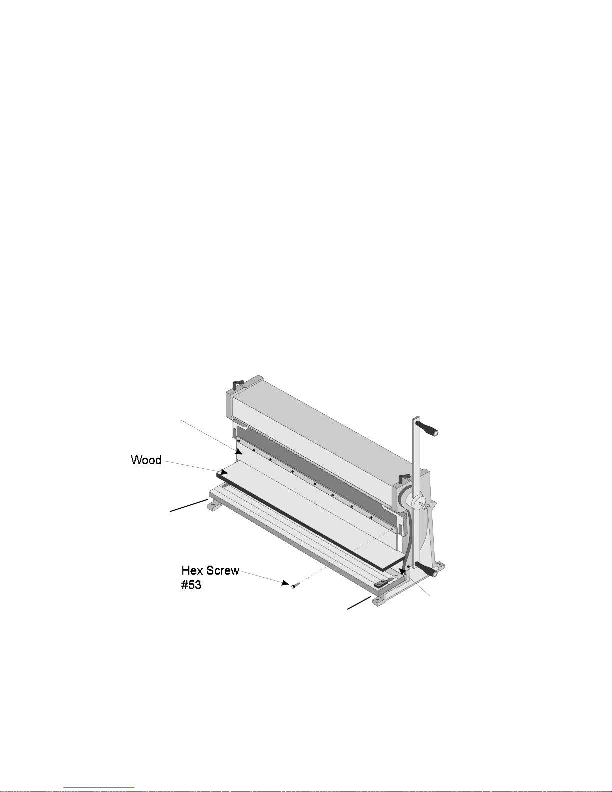
Step 1. Place a flat straight piece of wood between the UPPER BRAKING DIE and MOVING
CUTTER PLATE and raise the MOVING CUTTER PLATE so that the material just
touches the UPPER DIE as shown in Figure 1.
Upper Braking
Die #12
Adjusting Screw #61
Adjusting Screw #61
Moving Cutter Plate #11
Figure 1 — Adjusting the Dies
Step 2. Loosen the HEX SCREWS (#53) holding the UPPER DIE fingers in place. It is not
necessary to remove them.
Page 3 -- SKU: 05907 REV 11/02
Page 4
Step 3: Remove any unneeded UPPER DIE fingers.
Step 4. Raise and lower the MOVING CUTTER PLATE and use the block of wood to adjust the
alignment of the UPPER DIE fingers.
Step 5: Tighten the UPPER DIE HEX SCREWS.
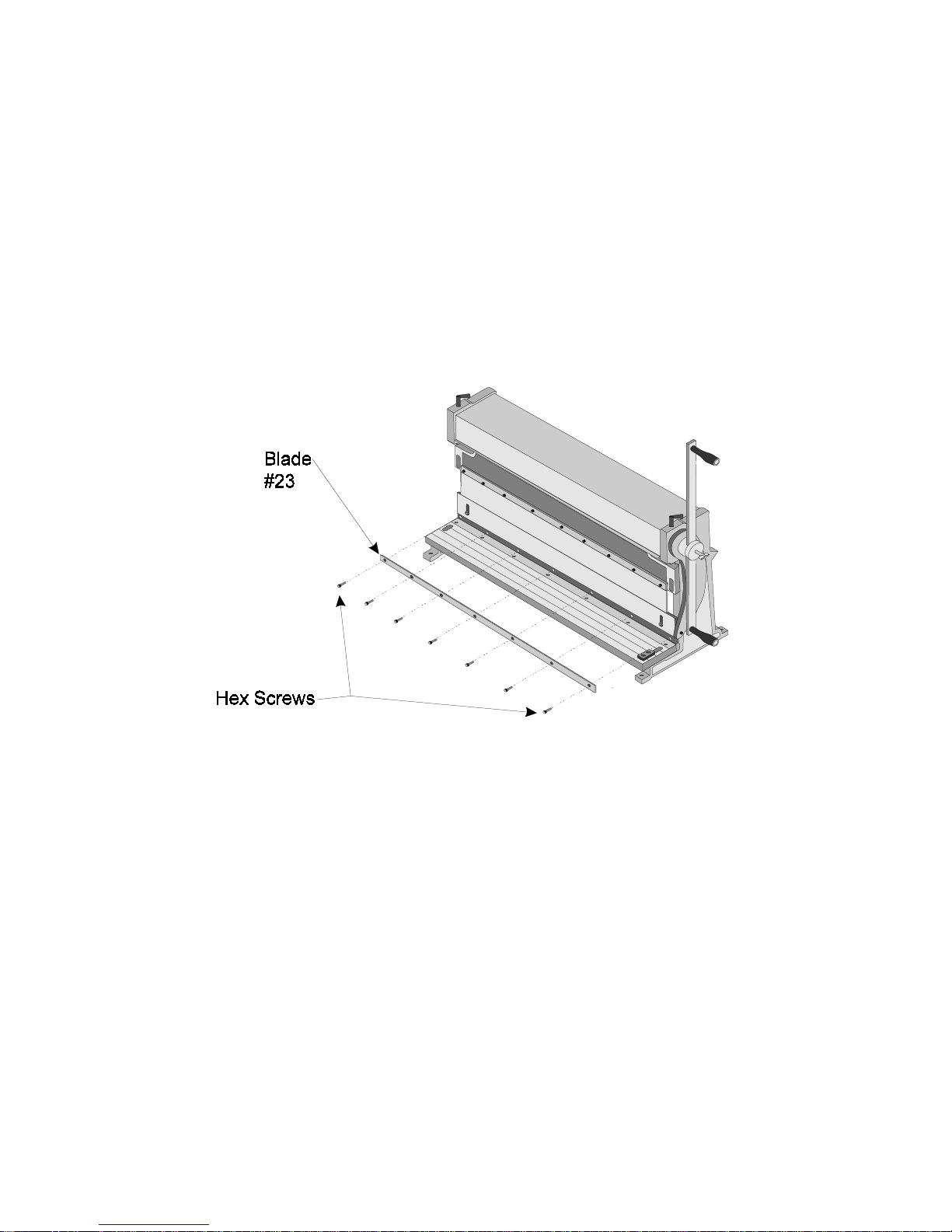
Removal and Installation of Upper Cutting Blade
Step 1: Remove the HEX SCREWS (#56) from the upper cutting BLADE (#23) as shown in
Figure 2.
#56
Figure 2 — Upper Blade Removal
Step 2: Remove the upper cutting BLADE.
Step 3: Align the upper cutting BLADE so that it is flush with the MOVING CUTTER PLATE
(#11) and secure with its SCREWS.
Adjustment of Upper Blade
Step 1: Place a 30” piece of thin cardboard or paper between the UPPER and LOWER
BLADES (#23).
Step 2: Rotate the HANDLE (#18) and cut the material.
Step 3: Use a straightedge to determine the straightness of the cut and if the BLADE is in need
of adjustment.
Page 4 -- SKU: 05907 REV 11/02
Page 5
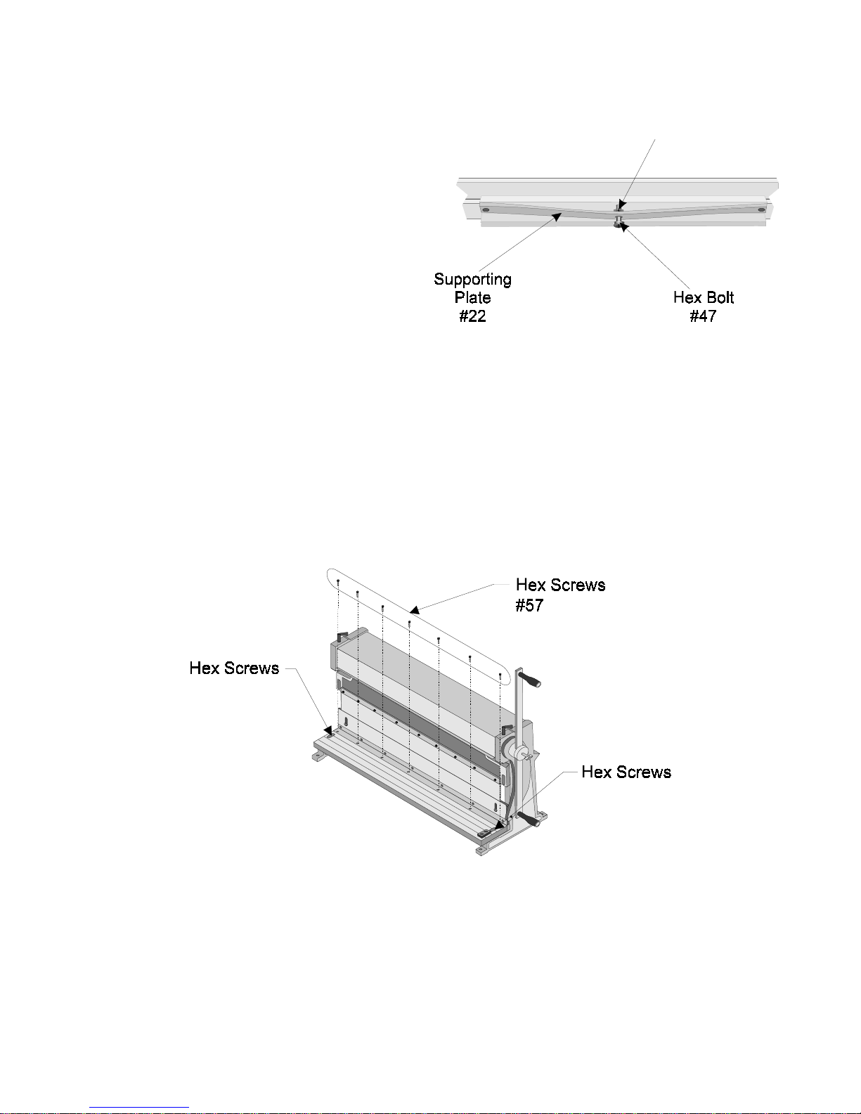
Step 4: If the BLADE is bowed out, away
from the front of the tool, turn the
Nut
#49
adjustment NUT (#49) counterclockwise (see Figure 3). This will tighten
the SUPPORTING PLATE (#22) and
push the middle of the UPPER
BLADE (#23) out while pulling its
ends in.
Step 5: If the BLADE is bowed in, towards
the back of the tool, turn the adjustment NUT clockwise (see Figure 3).
This will loosen the SUPPORTING
PLATE and pull the middle of the
UPPER BLADE in while pushing
Figure 3 — Upper Blade Alignment
its ends out.
Removal and Installation of Lower Blade
Step 1: Remove the HEX SCREWS (#59) from the lower cutting BLADE (#23) as shown in
Figure 4.
#59
#59
Figure 4 — Removal and Installation of Lower Blade
Step 2: Remove the lower cutting BLADE (#23).
Step 3: Replace the lower cutting BLADE and secure using its HEX SCREWS.
Page 5 -- SKU: 05907 REV 11/02
Page 6

Adjustment of Lower Cutting Blade
Step 1: Lower the upper BLADE (#23) to its lowest position.
Step 2: Loosen the two inset HEX SCREWS (#59) located on top of the WORK TABLE (#2) as
shown in Figure 4.
Step 3: Adjust the lower cutting BLADE by turning its ADJUSTMENT SCREWS (#61) as
shown in the Parts Diagram on page 13. The distance between the lower cutting
BLADE and the upper cutting BLADE should be 5 to 8 percent of the thickness of the
workpiece.
Step 4: Tighten the two inset HEX SCREWS (#59) located on top of the cutting blade.
Page 6 -- SKU: 05907 REV 11/02
Page 7

OPERATION
Shearing
Step 1: Scribe the cutting mark on the material.
Step 2: Slide the material between the upper BLADE (#23) and the lower BLADE (#23) so that
the upper BLADE is positioned directly above the mark and the right hand side of the
material rests against the GUIDE (#16) as shown in Figure 5.
Step 3: While holding the material steady, rotate the HANDLE until the material has been cut.
Page 7 -- SKU: 05907
Figure 5 — Shearing
Page 8

Angle Bending
Step 1. Mark the work piece where you want to bend the material.
Step 2. Place material above the MOVING CUTTER PLATE (#11) as shown in Figure 6.
Upper Braking
Die #12
Moving Cutter
Pate #11
Figure 6 — Angle Bending
Step 3. Align the bending mark with the front edge of the UPPER DIE.
Step 4. Rotate the HANDLE (#18) until the desired angle has been formed. Use a protractor or
other measuring tool to ensure accuracy.
Page 8 -- SKU: 05907 REV 11/02
Page 9

Radius Bending
Radius bending is most commonly used to make cylinders and cones, as shown in Figure 7.
Both shapes are formed by making a series of small, closely spaced bends in the work piece.
Work
Bench
Figure 7 — Radius Bending
For cylinders, the bends are evenly spaced, i.e. every bend is identical.
For Cones, simply move one side of your stock out further than the other every time you make a
bend.
Pan Forming
The Hand Brake Roll can be used to make various sizes of pans. The maximum lip (side) height
supported by this tool is 1”.
To form a pan:
Step 1. Pre-measure and cut your material before bending. Notch the corners according to the
desired lip height as shown in Figure 8.
Step 2. Insert material between the UPPER BRAKING DIE (#12) and the MOVING CUTTER
PLATE (#11). Bend the material until as 90 degree angle has been formed.
Step 3. Rotate the material 90º counterclockwise. Allow the completed side to extend just
beyond the dies. Bend the second side.
Step 4. Repeat Step 3 for the third side.
Step 5. Rotate to the final side, and insert work piece between the dies. Your formed sides will
be on the outside of the dies.
Step 6. Before bending, tap one corner nearer to the middle of the machine. This will allow the
material to clear the UPPER BRAKING DIE when raised.
Page 9 -- SKU: 05907 REV 11/02REV 07/02
Page 10

Step 7. Bend the fourth side.
Step 8. Using a block or piece of wood, tap the corner of material back into place.
Step 2: Bend Second Side
plaplace.
Figure 8 — Pan Forming
Rolling
Step 1:Move the COVER (#33) back and out of the way.
Step 2:Drop the BACK PRESSING ROLL (#24) by loosening the SCREW (#25).
Step 3:Insert just the leading edge of your workpiece between the UPPER PRESSING ROLL
(#32) and LOWER PRESSING ROLL (#31), and tighten the roll bar gap ADJUSTABLE
BOLT (#27) until the ROLL BARS are barely snug against the workpiece.
Step 4:Advance the SCREW (#25) as much as desired depending upon the tightness of the roll
to be accomplish. (The tighter the roll, the more the knobs must be advanced.)
Step 5:Crank the HANDLE ASSEMBLY (#18 & 26) until the proper roll has been achieved. The
material should feed itself through the rollers as you crank the HANDLE ASSEMBLY.
Page 10 -- SKU: 05907 REV 11/02
Page 11

Wire Rolling
Step 1:Use the proper groove in the UPPER PRESSING ROLL (#32) depending upon the
gauge of the wire being rolled.
Step 2: Follow the procedures as listed above in “Rolling”.
Pressing
Step 1:Slide the PRESS PLATE BRACKETs (#8) of the Press Plate Assembly into the receiver
holes of the MOVING CUTTER PLATE (#11). Note that the PRESSING PLATE (#10)
should be facing down.
Step 2:Place the workpiece so that it is centered under the PRESS PLATE.
Step 3:Rotate the HANDLE (#18) to press the workpiece.
Page 11 -- SKU: 05907 REV 11/02
Page 12

PARTS LIST
PART # DESCRIPTION Qty PART # DESCRIPTION Qty
1 Left Wall 1 32 Upper Pressing Roll 1
2 Work Bench 1 33 Cover 1
3 Crossbeam 1 34 Pressing Roll Lock 1
4 Crank Arm 2 35 Eccentric Shaft 2
5 Right Wall 1 36 Jacket 2
6 Bear Frame 1 37 Roll Key 4
7 Cover 2 38 Hex Bolt 4
8 Press Plate Bracket 2 39 Hex Screw 2
9 Spring 2 40 Hex Bolt 2
10 Pressing Plate 1 41 Hex Bolt 1
11 Moving Cutter Plate 1 42 Hex Bolt 2
12 Upper Braking Die 1 43 Hex Screw 2
13 Pressing Plate 1 44 Hex Screw 2
14 Screw 2 45 Washer 2
15 Rolling Wheel 2 46 Hex Bolt 1
16 Guide 1 47 Hex Bolt 2
17 Adjustable Bolt 2 48 Washer 2
18 Handle 2 49 Hex Nut 1
19 Positioning Bar 2 50 Hex Srew 2
20 Positioner 2 51 Hex Screw 2
21 Positioning Plate 1 52 Hex Screw 7
22 Support Plate 1 53 Hex Screw 4
23 Blades 2 54 Washer 2
24 Back Pressing Roll 1 55 Hex Bolt 2
25 Screw 2 56 Hex Screw 7
26 Handle Knob 2 57 Hex Screw 2
27 Adjustable Screw 2 58 Hex Screw 7
28 Roll Bushings 4 59 Hex Screw 2
29 Washer 2 60 Clamp Screws 2
30 Gear 2 61 Adjusting Screws 2
31 Lower Pressing Roll 1
Page 12 -- SKU: 05907 REV 11/02
Page 13

Parts Diagram
#5907 30” Shear Brake Roll
61
61
Page 13 -- SKU: 05907 REV 11/02
Page 14

27
32
IN
24
31
26
SKU 05907
SHEET METAL & WIRE FORMING
Remove the cover (#33) from the machine. The roller gears (#30) should have a coating
of general purpose grease for smooth operation. Clean any dirt or excess grease from
the rolls.
The following steps apply to both wire and sheet metal bending.
Adjust screws (#27) to the thickness of the stock. It should feed between rollers (#31) and
(#32) without slipping or binding when the handle (#18) is turned. The material is fed into
the rollers from the front of the machine.
Back Pressing Roll (#24) forms the radius in the material. The closer it is to the feed
rollers, the smaller the radius will be. Handle Knobs (#26) adjusts the spacing of the back
roller.
Metals will have different bending characteristics. Some are very pliable, while others
have considerable spring or memory. Practice before beginning an important project.
Page 14 -- SKU: 05907
REV 11/02
 Loading...