

Page 1
MINI-HOBBY WOODWORKING LATHE
®
Model 03173
ASSEMBLY AND OPERATING INSTRUCTIONS
3491 Mission Oaks Blvd., Camarillo, CA 93011
Visit our Web site at: http://www.harborfreight.com
Copyright 2002 by Harbor Freight Tools®. All rights reserved. No portion of this
manual or any artwork contained herein may be reproduced in any shape or form
without the express written consent of Harbor Freight Tools.
For technical questions, please call 1-800-444-3353.
Page 2

PRODUCT SPECIFICATIONS
Item Description
Features Woodworking Lathe / 12 VDC High Speed Motor With Switch /
12 Volt Transformer / Turning Gouge / Allen Key / Center Finder /
Assembly Hardware.
Electrical
Requirements
Construction ABS Plastic (Glass Reinforced) / Cast Aluminum /
Net Weight 10.70 Pounds.
120 VAC Input / 60 Hz / 12 VDC Output /
6 Watts / 18,000 RPM.
Aluminum Alloy / Stainless Steel / Low Carbon Steel.
SAVE THIS MANUAL
You will need this manual for the safety warnings and precautions, assembly,
operating, inspection, maintenance and cleaning procedures, parts list and
assembly diagram. Keep your invoice with this manual. Write the invoice number on the inside of the front cover. Keep this manual and invoice in a safe and
dry place for future reference.
GENERAL SAFETY WARNINGS AND PRECAUTIONS
1. KEEP WORK AREA CLEAN AND DRY. Cluttered, damp, or wet wor k areas
invite injuries.
2. KEEP CHILDREN AWAY FROM WORK AREA. Do not allow children to handle
this product.
3. STORE IDLE EQUIPMENT. When not in use, tools and equipment should be
stored in a dry location to inhibit rust. Always lock up tools and equipment, and
keep out of reach of children.
4. DO NOT USE THIS PRODUCT IF UNDER THE INFLUENCE OF ALCOHOL OR
DRUGS. Read warning labels on prescriptions to determine if your judgement or
reflexes are impaired while taking drugs. If there is any doubt, do not attempt to
use this product.
5. USE EYE AND BREATHING PROTECTION. Wear ANSI approved safety impact
eyeglasses and a full face shield when using this product. Also, use an ANSI
approved dust mask if the operation produces excessive dust. ANSI approved
safety impact eyeglasses, full face shield, and dust masks are available from
Harbor Freight Tools.
6. DRESS SAFELY. Do not wear loose clothing or jewelry, as they can become
caught in moving parts. Wear a protective hair covering to prevent long hair from
becoming caught in moving parts. If wearing a long-sleeve shirt, roll sleeves up
above elbows.
SKU 03173 PAGE 2 REV 01/04
Page 3

7. DO NOT OVERREACH. Keep proper footing and balance at all times to prevent
tripping, falling, back injury, etcetera.
8. INDUSTRIAL APPLICATIONS MUST FOLLOW OSHA REQUIREMENT.
9. STAY ALERT. Watch what you are doing at all times. Use common sense. Do
not use this product when you are tired or distracted from the job at hand.
10. CHECK FOR DAMAGED PARTS. Before using this product, carefully check that
it will operate properly and perform its intended function. Check for damaged
parts and any other conditions that may affect the operation of this product.
Replace or repair damaged or worn parts immediately.
11. REPLACEMENT PARTS AND ACCESSORIES: When servicing, use only
identical replacement parts. Only use accessories intended for use with this
product. Approved accessories are available from Harbor Freight Tools.
12. MAINT AIN THIS PRODUCT WITH CARE. Keep this product clean, dr y, and
keep all cutting bits sharp for better and safer performance. For your safety,
service and maintenance should be performed regularly by a qualified technician.
13. USE THE RIGHT TOOL FOR THE JOB. Do not attempt to force a small tool or
attachment to do the work of a larger industrial tool. There are certain applications for which this tool was designed. It will do the job better and more safely at
the rate for which it was intended. Do not modify this tool, and do not use this
tool for a purpose for which it was not intended.
14. WARNING: The warnings, precautions, and instructions discussed in this manual
cannot cover all possible conditions and situations that may occur. The operator
must understand that common sense and caution are factors, which cannot be
built into this product, but must be supplied by the operator.
SPECIFIC PRODUCT WARNINGS AND PRECAUTIONS
1. FOR THEIR SAFETY AND THE SAFETY OF OTHERS, NEVER ALLOW
CHILDREN TO USE THIS PRODUCT WITHOUT CLOSE ADULT
SUPERVISION.
2. TO AVOID KICKBACK, ALWAYS MAINTAIN A FIRM GRIP ON THE CUTTING
TOOL WITH BOTH HANDS, AND APPLY FIRM DOWNWARD PRESSURE ON
THE WOODTURNING SUPPORT (part #18).
3. MAINTAIN A SAFE WORKING ENVIRONMENT. Keep the work area well lit.
Make sure there is adequate surrounding workspace. Always keep the work
area free of obstructions, grease, oil, trash, and other debris. Do not use
SKU 03173 PAGE 3
Page 4
the Woodworking Lathe in areas near flammable chemicals, dusts, and vapors.
Do not use the Woodworking Lathe in a damp or wet location.
4. BEFORE USING THE WOODWORKING LATHE, make sure it is positioned on a
flat, level, sturdy workbench surface capable of supporting the weight of the tool,
additional tools, accessories, and the workpiece.
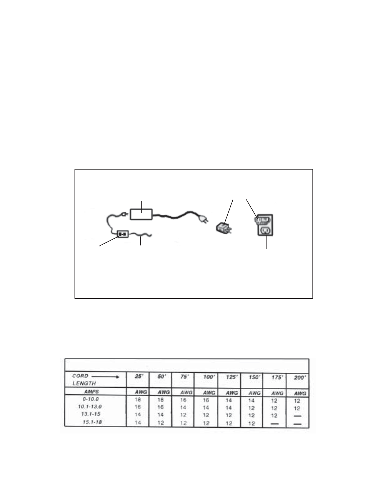
5. GROUND THIS PRODUCT . The 12 Volt Transformer for this product is equipped
with a 2-prong Plug and requires the use of a grounded, 3-Prong Adapter Plug
(not included). To comply with the National Electr ic Code, and to provide additional protection from the risk of electrical shock, this product should only be
connected to a 120 Volt, 3-hole electr ical outlet that is protected by a Ground
Fault Circuit Interrupter (GFCI). (See Figure A.)
3-PRONG ADAPTER PLUG
12 VOLT TRANSFORMER (#58)
(NOT INCLUDED)
ON/OFF
POWER
SWITCH
POWER CORD OF
HIGH SPEED
MOTOR UNIT (#4-A)
120 VOLT, GROUNDED
ELECTRICAL OUTLET
FIGURE A
6. IF AN EXTENSION CORD (not included) IS USED, MAKE SURE TO USE
ONLY UL APPROVED CORDS HAVING THE CORRECT GAUGE AND
LENGTH. (See Figure B.)
AWG RATING CHART - 120 VOLT
FIGURE B
SKU 03173 PAGE 4
Page 5

7. WARNING: Some dust created by power sanding, sawing, grinding, drilling, and
other construction activities, contain chemicals known (to the State of California)
to cause cancer, birth defects or other reproductive harm. Some examples of
these chemicals are: lead from lead-based paints, crystalline silica from bricks
and cement or other masonry products, arsenic and chromium from chemically
treated lumber. Your r isk from these exposures varies, depending on how often
you do this type of work. To reduce your exposure to these chemicals: work in a
well ventilated area, and work with approved safety equipment, such as those
dust masks that are specially designed to filter out microscopic particles.
(California Health & Safety Code 25249.5, et seq.)
8. WARNING: People with pacemakers should consult their physician(s) before
using this product. Operation of electrical equipment in close proximity to a heart
pacemaker could cause interference or failure of the pacemaker.
UNPACKING
When unpacking, check to make sure all the par ts shown on the Parts List on page 10
are included. If an y parts are missing or broken, please call Harbor Freight Tools at the
number shown on the cover of this manual as soon as possible.
ASSEMBLY INSTRUCTIONS
NOTE: For additional references to the parts listed below, refer to the Assembly
Diagram on page 12.
The Electrical Power Supply:
1. The electrical power supply system for the Multi-Purpose Machine consists of
one 12 Volt Transformer (part #58). (See Figure A.)
2. CAUTION: Always make sure the On/Off Power Switch (located on the
Electrical Cord) is in its “OFF” position prior to plugging the
12 Volt Transformer (part #58) into a grounded, 120 volt electrical outlet.
(See Figure A.)
3. To supply electrical power to a machine tool, plug the Power Cord of the High
Speed Motor Unit (part #4-A) into the outlet of the 12 Volt Transformer (part #58).
(See Figure A.)
4. Then, plug the Power Cord of the 12 Volt Transformer (part #58) into a grounded,
120 volt, electrical outlet. (See Figure A.)
SKU 03173 PAGE 5
Page 6

2. CAUTION: Always make sure the On/Off Power Switch, located on the
Power Cord of the High Speed Motor Unit (part #4-A) is in its “OFF” position prior to plugging the 12 Volt Transformer (part #58) into a grounded,
120 volt electrical outlet.
(See Figure A.)
3. To supply electrical power to the Woodturning Lathe, plug the Power Cord of the
High Speed Motor Unit (part #4-A) into the outlet of the 12 Volt Transformer
(part #58).
(See Figure A.)
4. Then, plug the Power Cord of the 12 Volt Transformer (part #58) into a grounded,
120 volt, electrical outlet. (See Figure A.)
To Connect The Parts, Using The Connection Pieces:
1. Each of the main parts of the Woodworking Lathe features one or more “T”
Slots with which to connect one part to another. (See Figure C.)
2. As an example, the High Speed Motor Unit (part #4-A) and the Wheel Gear Box
(part #6) will be used to illustrate how the two parts, as with other parts, are
connected together. (See Figure C.)
CONNECTION PIECE (#19)
SCREW
(#84)
HIGH SPEED MOTOR UNIT (#4-A)
“T” SLOT
CONNECTION PIECE (#19)
NUT (#93)
DRIVE BELT (#15)
WHEEL GEAR BOX (#6)
SKU 03173 PAGE 6
SCREWDRIVER
(NOT INCLUDED)
FIGURE C
Page 7

3. First, insert one Bolt completely through a Connection Piece
(part #19), and loosely screw a Nut onto the Bolt.
(See Figure C.)
4. Insert the Connection Piece (part #19) midway into the bottom Small “T” Slot of
the High Speed Motor Unit (part #4-A). Observe that the lower portion of the
Connection Piece is exposed. (See Figure C.)
5. Insert the top Small “T” Slot of the Wheel Gear Box (part #6) midway onto the
exposed portion of the Connection Piece (part #19). Make sure the Wheel Gear
Box and High Speed Motor Unit (part #4-A) are aligned. Using a Screwdriver
(not included), firmly tighten the Bolt to secure the Wheel Gear Box (part #6) to
the High Speed Motor Unit (part #4-A).
(See Figure C.)
6. NOTE: Once the Wheel Gear Box (part #6) is connected to the High Speed
Motor Unit (part #4-A) ALWAYS attach the Drive Belt Cover (part #17) to the
back of both the Wheel Gear Box and High Speed Motor Unit.
(See Figure C, and Assy. Diagram.)
To Assemble The Wood Turning Lathe:
1. Insert two assembled Connection Pieces (part #19) into the
Machine Bed (part #1). Then, attach the Large Slide (part #9) to the front side of
the Long Machine Bed. (See Figure E, next page.)
2. Insert one assembled Connection Piece (part #19) into the top right and left ends
of the Long Machine Bed (part #1). Attach the pre-assembled High Speed Motor
Unit (part #4-A) and Wheel Gear Box (part #6) to the top left end of the Long
Machine Bed. Then, attach the Tailstock (part #7) to the top right end of the Long
Machine Bed. (See Figure E.)
3. Attach the W ood Turning Support (part #18) to the top of the Large Slide
(part #9), using one Screw (part #87) and one Slot Nut (part #60).
(See Figure E.)
4. Attach a Drive Center (part #31) to the Wheel Gear Box (part #6.)
(See Figure E.)
front side
of the Long
SKU 03173 PAGE 7
Page 8

5. Attach a Live Center (part #28) to the Tailstock (part #7), using a Collet (part #71)
and Collet Holder (part #35). (See Figure E.)
LONG MACHINE
BED (#1)
CONNECTION
PIECE (#19)
WOOD TURNING
HIGH SPEED
MOTOR
UNIT (#4-A)
WHEEL
GEAR
BOX (#6)
SUPPORT (#18)
DRIVE CENTER (#31)
SCREW (#87)
SLOT NUT (#60)
LIVE
CENTER
(#28)
LARGE SLIDE (#9)
TAIL
STOCK
(#7)
WOODWORKING LATHEFIGURE E
SKU 03173 PAGE 8
Page 9

BASIC POWER MACHINE TOOL OPERATION TIPS
1. Keep all safety guards in place, in proper adjustment, and in proper alignment.
2. Make sure the On/Off Power Switch (located on the Electrical Cord) is in the “OFF” position
before plugging the 12 Volt Transformer (part #58) into a grounded, 3-hole, 120 Volt, electrical
outlet.
3. Prior to starting a power machine tool, make sure all adjusting keys and wrenches are removed
from the tool.
4. Always keep a firm grip on the tool with both hands, and whenever possible secure the
workpiece with a vise or clamps (not included).
5. Always feed the Turning Gouge (part #49) into and against the rotational direction of the
woodstock.
6. Never leave a power machine tool unattended when it is running. Turn off the tool, and wait until
it has completely stopped before leaving.
7. Always unplug a power machine tool from its electrical supply source before performing any
inspection, maintenance, or cleaning procedures.
WOODWORKING LATHE OPERATING INSTRUCTIONS
1. On both ends of the woodstock workpiece (not included), locate and mark the center, using the
Center Finder (part #30). (See Assy. Diagram.)
2. Align the marked center of one end of the woodstock with the Drive Center (part #31), and align
the marked center of the other end of the woodstock with the Live Center (part #28).
(See Figure E.)
3. Turn the Handle on the Tailstock (par t #7)
(See Figure E.)
4. Turn the Handle of the Large Slide (part #9) clockwise, or counterclockwise, to move the Large
Slide horizontally to the desired position in front of the woodstock. (See Figure E.)
5. Connect the Power Cord of the High Speed Motor Unit (par t #4-A) to the 12 Volt Transformer
(part #58). Plug the 12 Volt Transformer into a grounded, 120 volt electrical outlet. Then, turn the
Power Switch to its “ON” position. (See Figure A.)
6. Wait until the Woodworking Lathe is turning the woodstock at full speed. Grasp the Turning
Gouge (part #49) fir mly with both hands. Rest the Turning Gouge fir mly on the Wood Turning
Support (part #18). (See Figure E.)
7. Slowly and carefully, move the cutting tip of the Turning Gouge (part #49) forward into the revolving woodstock, steadily applying forward pressure to make the desired depth of cut.
8. To make a cut in a different location on the woodstock pull the Turning Gouge (part #49) away
from the woodstock, and turn the Handle of the Large Slide (part #9) clockwise or counterclockwise to reposition the Large Slide. (See Figure E.)
clockwise
until the woodstock is held firmly in place.
SKU 03173 PAGE 9
Page 10

9. Continue cutting the woodstock until the job is finished. Then turn the Power Switch to its “OFF”
position, and unplug the Woodworking Lathe from its electricl outlet.
10. Wait until the woodstock has completely stopped revolving before removing it from the Woodworking Lathe.
INSPECTION, MAINTENANCE, AND CLEANING
1. CAUTION: Always unplug the 12 Volt Transformer (part #58) from its 120 volt electrical outlet
before performing any inspection, maintenance, or cleaning.
2. BEFORE EACH USE, inspect the general condition of the Multi-Purpose
Machine. Check for loose screws, misalignment or binding of moving parts, cracked or broken
parts, damaged electrical wiring, and any other condition that may affect its safe operation. If
abnormal noise or vibration occurs, have the problem corrected before further use. Do not use
damaged equipment.
3. DAILY: With a soft brush, cloth, or vacuum, remove all debris from the
Multi-Purpose Machine. Then, use a premium quality, lightweight machine oil to lubricate all
moving parts.
PARTS LIST
Part # Description Qty. Part # Description Qty.
1 Machine Bed, Long 1 46 Allen Key 1
4-A High Speed Motor Unit w/Switch 1 49 Turning Gouge 1
6 Wheel Gear Box 1 52 Motor’s Leaf Slice 1
7 Tail Stock 1 53 0.3 Small Plate 5
9 Slide, Large 1 54 0.4 Small Plate 5
15 Drive Belt 1 5 8 1 2 Vo lt Transformer 1
17 Drive Belt Cover 1 60 Slot Nut 2
18 Woodt ur ning Support 1 61 Two Hole Clamping Plate 2
19 Connection Piece 5 71 Collet 1
28 Live Center 1 83 Bolt (3 x 10) 2
30 Center Finder 1 85 Screw (4 x 6) 1
31 Drive Center 1 87 Screw (4 x 10) 1
35 Co lle t Holder 1
SKU 03173 PAGE 10
Page 11

ASSEMBLY DIAGRAM
NOTE: Some parts are listed and shown for illustration purposes only, and are not
available individually as replacement parts.
SKU 03173 PAGE 11
 Loading...