

Page 1
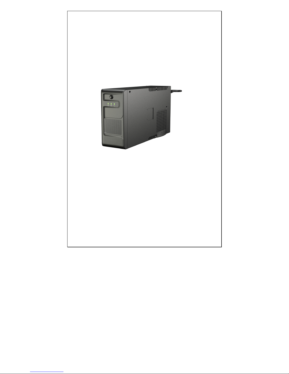
USER’S MANUAL
ENDURE 500VA
ENDURE 750VA
ENDURE 1000VA
ENDURE 2000VA
Page 2

Important Safety Information
Before installing UPS Endure 500VA/750VA/1000VA/2000VA, please read the operating
instructions carefully. Special attention must be paid to the CAUTION and WARNING
statements in this manual.
CAUTION
1. To reduce risk of injury, use ONLY lead-acid type rechargeable batteries. Other types of
batteries may cause damage and injury.
2. DO NOT operate the Endure UPS if it has been dropped or damaged in any way.
3. DO NOT expose Endure UPS to rain, snow or liquids of any type. Endure UPS is
designed for indoor installation only.
4. DO NOT disassemble Endure UPS; it contains no user-serviceable parts. Take it to an
authorized service center only, when service or repair is required.
5. NEVER charge a frozen battery.
6. DO NOT obstruct the ventilation openings.
WARNING
1. Provide adequate ventilation for the battery compartment. The battery enclosure should
be designed to prevent accumulation and concentration of hydrogen gas at the top of the
compartment.
2. Input/output AC wiring and battery cables must be rated for 75oC or higher. Using cables
diameter, to find out the rating, please refer to appendix A, according to different models.
The inner diameter of the copper ring terminal which is used to connect battery cables to
DC terminals should be no less than 6mm.
3. For battery installation and maintenance: read the battery manufacturer’s installation and
maintenance instructions prior to operating.
PERSONAL PRECAUTIONS
1. Have plenty of fresh water and soap nearby in case battery acid contacts skin, clothing,
or eyes.
2. Avoid touching eyes while working near batteries.
3. NEVER smoke or allow a spark or flame in the near vicinity of a battery.
4. Remove personal metal items such as rings, bracelets, necklaces, and watches while
working with batteries. Batteries can produce short circuit current high enough to make
metal melt, and can cause severe burns.
5. If a remote or automatic generator start system is used, disable the automatic starting
circuit or disconnect the generator to prevent accident during servicing.
Salient Features:
Endure UPS series, powers from AC power and DC source, serving as an extended run UPS.
When AC cable is connected to a wall socket, utility power goes to connected equipment(s)
and/or charges the battery set via charging system. In UPS mode, the Endure UPS series
automatically converts battery energy into AC power for backup the connected devices.
●
Up to 10A large charging ability for connecting extra external batteries
Page 3
●
Equipped with 2-boosts and 1-buck AVR for stabilizing output voltage
●
Wider input voltage range design from 140Vac to 300Vac
●
High reliable AC output voltage
●
Microprocessor control design for desirable reliability
●
Built-in DC start function for starting up the system without mains power
●
Provides Modem/Phone line surge protection (optional) and overload protection
●
Optional RS-232 and USB Communication Port
●
WinPower, free software available online for real-time status monitoring and controlling
●
Auto restart when AC utility is recovered
●
Support Generator Input
●
High Frequency Design with high DC-AC Efficiency for higher than 85%
Operation & Installation
Front Panel Controls and LED Indicators
Shown below are the controls and indicator lights on the front of UPS Endure
500VA/750VA/1000VA/2000VA.
Page 4
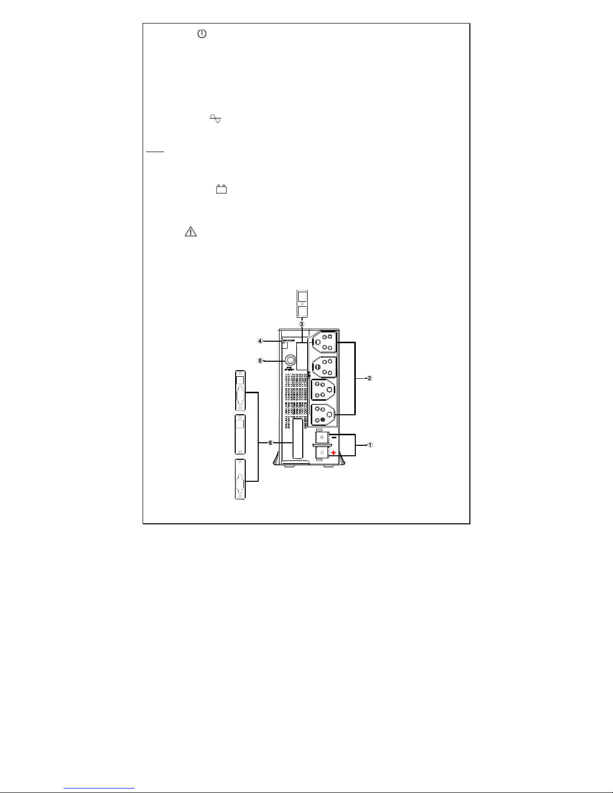
Power On/Off
Power on/off button is shown as above. Once UPS unit has been properly installed and
batteries are connected, press this button and UPS will turn on automatically, and works in
‘mains’ mode or ‘inverter’ mode according to the status of input AC source. Press again, to turn
off UPS unit.
Mains Mode LED
The green LED will light steadily when power mains are normal.
Note: The green LED blinks every 2 seconds to indicate that battery is not fully charged when
the unit switch on.
Inverter Mode LED
The Yellow LED will light, when power mains are abnormal, and unit will work in ‘inverter’
mode.
Fault LED
Red LED will blink or light steadily when fault occurs.
Back Panel Description
Shown below are the components on the back of UPS.
Page 5
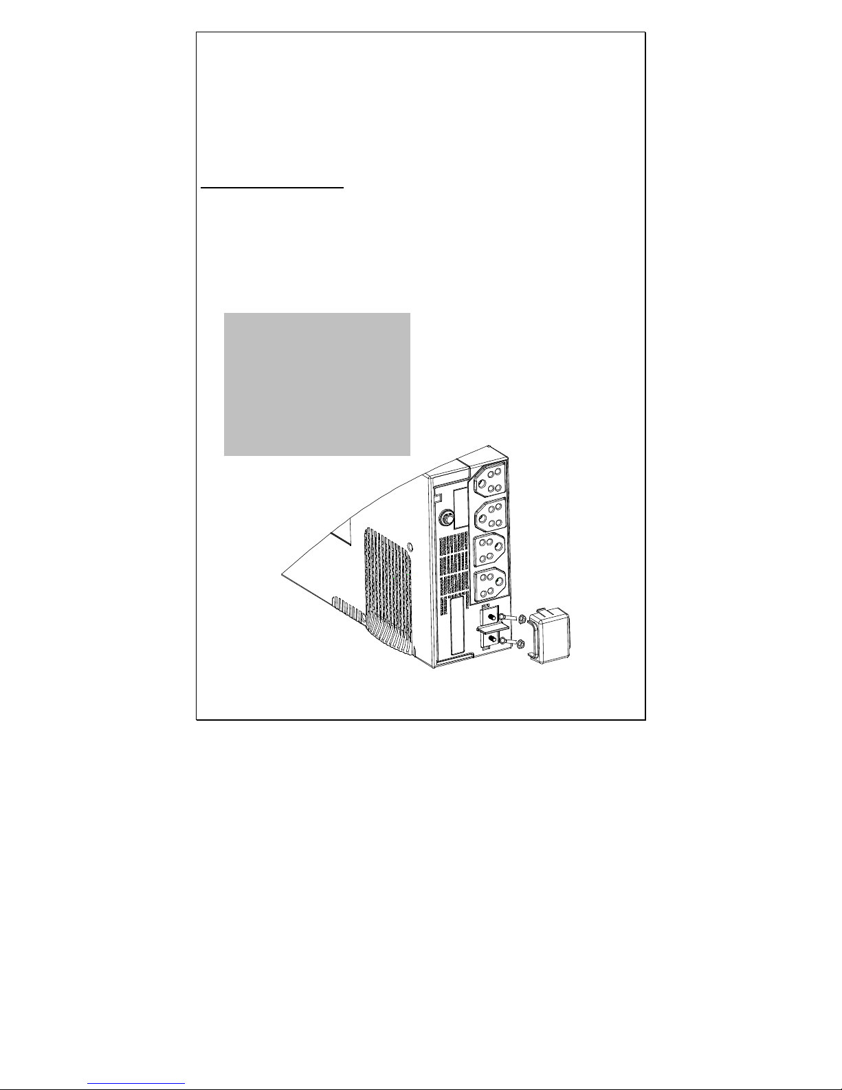
1. DC Input Connector (Battery Terminal)
2. Output Receptacle(s)
3. TVSS port (optional)
4. AC Input power cord
5. Input Breaker
6. Communication port (USB,RS232,optional)
Battery Connection
Step 1- Pinch the bottom of DC input cover and Open it.
Step 2- Follow battery polarity guide located near battery terminal. Place the battery cable ring
terminal over Endure’s battery terminal. Tighten the M5 nut. Do not place anything
between the flat part of battery terminal and the battery cable ring terminal, since
overheating may occur.
Battery Cable Connection to UPS Endure 500VA/750VA/1000VA/2000VA
Caution!
DO NOT place
anything between battery
cable ring terminals and
battery terminals. The
terminal stud is not designed
to carry current. Apply
Anti-oxidant paste to
terminals after terminals
have been torqued.
Page 6
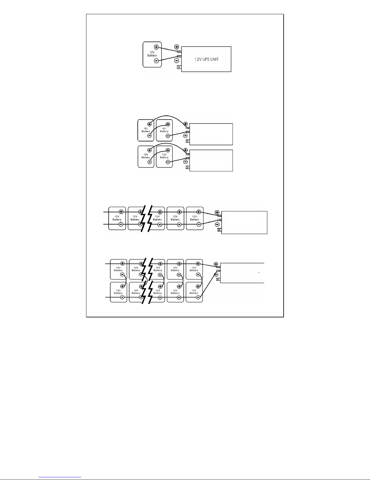
Step 3- Connect battery cables to your batteries
The battery must be wired to match the units DC input voltage specifications (12V for
500VA/750VA/1000VA, 24V for 2000VA )
In addition, the batteries can be wired to provide additional run time. The various wiring
configurations are as follows:
Series Connection: Wiring batteries in “series” increases the total output voltage. This
voltage MUST match the DC voltage requirements of the UPS unit, or it may damage both
the UPS unit and/or the batteries.
Parallel Connection: Wiring batteries in “parallel” increases the total run times; the batteries
can operate the AC loads. The more batteries connected in parallel the longer the loads can
be powered from the UPS unit.
Series-Parallel Connection: “Series-parallel” configuration increases both the battery
voltage (to match the DC requirements of UPS unit) and run time for operating the AC loads.
ENDURE 500
ENDURE 750
ENDURE 500
ENDURE 750
ENDURE 2000
ENDURE 2000
Page 7
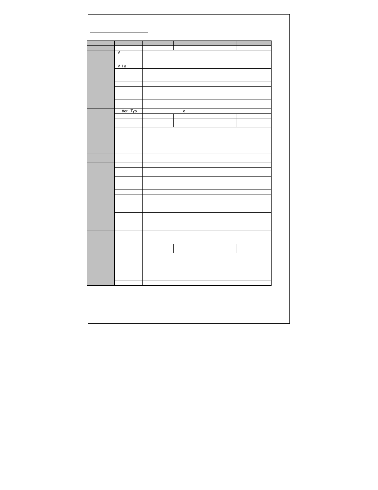
SPECIFICATIONS
MODEL
Endure 500
Endure 750
Endure 1000
Endure 2000
CAPACITY
VA/W 500VA/300W 750VA/450W 1000VA/600W 2000VA/1200W
INPUT
Voltage 220/230/240VAC
Voltage
Range 140-300VAC
OUTPUT
Voltage 220/230/240VAC
Voltage
Regulation(
Batt. Mode) +12% / -18%
Frequency 50Hz or 60Hz
Frequency
Regulation
(Batt. Mode)
+/-0.1 Hz
Output
Waveform Modified Sinewave
BATTERY
Battery Type
Rechargeable lead-acid battery
DC voltage 12V 12V 12V 24V
Charger
Current
10 Amp +/-
1Amp
10 Amp +/-
1Amp
10 Amp +/-
1Amp
10 Amp +/-
1Amp
Back up
Time (at a
PC load with
15" monitor)
Determined by external battery capacity
Recharge
Time Determined by external battery capacity
TRANSFER
TIME
Typical 4-8 ms typical, 14 ms max
INDICATOR
AC Mode Green lighting
Battery
Mode Yellow lighting
Battery
Charging
Mode
When battery is not full enough in line mode, green flashing every 2
seconds
When battery full, green lighting
Overload Red flashing every 0.5 second
Fault Red lighting
AUDIBLE
ALARM
Battery
Mode Sounding every 10 seconds
Low Battery Sounding every 2 seconds
Overload Sounding every 0.5 second
Fault Continuously sounding
PROTECTI
ON
Full
Protection
Discharge, overcharge, and overload protection
PHYSICAL
Dimension,
DXWXH
(mm)
402X117X222
Net Weight
(kg) 4 4.5 4.9 6.5
ENVIRONM
ENT
Operating
Environment
0- 40°C, 0-90 % relative humidity (non-condensing)
Noise Level Less than 50dB
INTERFAC
E
Smart
RS-232
Option
Support Windows family, Linux, IBM Aix, Sun Solaris, Compaq True64,
UnixWare, FreeBSD, HP-UX, and MAC
USB Option Windows family and MAC
Page 8
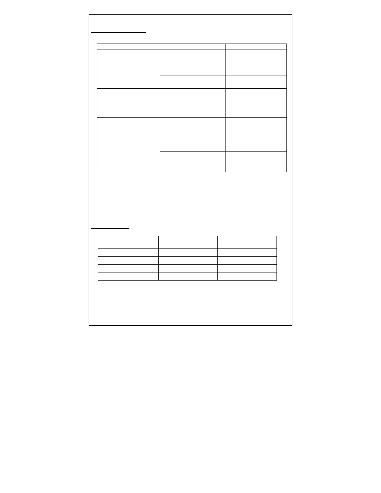
Troubleshooting
Problem Possible Causes Remedy
No LED display
1. Battery Weak
Re-charge battery
2. Battery defective
Battery replacement.
3. Power switch is not
pressed
switch.
Mains normal but
works in inverter
mode
1. AC Input missing
Check AC input
connection.
2. Input protector is
effective
Reset the input protector.
Alarm buzzer beeps
continuously
Overload
Verify that the load
matches the capability
specified in the specs.
Back up time is
shortened
Overload
Remove some
non-critical load.
Battery voltage is too
low.
Charge battery for 8
hours or more.
If any abnormal situations occur that are not listed above, please call
service personnel immediately.
Appendix A
Models
Input/output cables
(gauge copper wire)
Battery cables
(gauge copper wire)
500VA/12VDC (HV) At least 18AWG At least 10AWG
750VA/12VDC (HV) At least 18AWG At least 10AWG
1000VA/12VDC (HV) At least 18AWG At least 8AWG
2000VA24VDC (HV) At least 16AWG At least 8AWG
 Loading...