

2 TON ALUMINUM LOW
PROFILE RACING JACK
ASSEMBLY AND OPERATING INSTRUCTIONS
92782
Distributed exclusively by Harbor Freight Tools®.
3491 Mission Oaks Blvd., Camarillo, CA 93011
Visit our website at: http://www.harborfreight.com
Read this material before using this product.
Failure to do so can result in serious injury.
SAVE THIS MANUAL.
Copyright© 2005 by Harbor Freight Tools®. All rights reserved. No portion of this manual or any artwork
contained herein may be reproduced in any shape or form without the express written consent of Harbor Freight
Tools. Diagrams within this manual may not be drawn proportionally. Due to continuing improvements, actual
product may differ slightly from the product described herein. Tools required for assembly and service may not
be included.
For technical questions or replacement parts, please call 1-800-444-3353.

Specifications
Lift Capacity 4000 Lbs.
Lifting Range 3-1/4” to 18-1/4”
Overall Dimensions 27-1/2” x 12” x 9-1/12”H
Saddle Pad Dimensions 3-5/8”L x 3-5/8”W x 1/4”T
Weight 45.40 Lbs.
Save This Manual
You will need the manual for the safety warnings and precautions, assembly instructions,
operating and maintenance procedures, parts list and diagram. Keep your invoice with this
manual. Write the invoice number on the inside of the front cover. Keep the manual and
invoice in a safe and dry place for future reference.
Safety Warnings and Precautions
WARNING: When using tool, basic safety precautions should always be followed to
reduce the risk of personal injury and damage to equipment.
Read all instructions before using this tool!
1. Keep work area clean. Cluttered areas invite injuries.
2. Observe work area conditions. Do not use machines or tools in damp or wet
locations. Don’t expose to rain. Keep work area well lit.
3. Keep children away. Children must never be allowed in the work area. Do not let
them handle machines, or tools.
4. Store idle equipment. When not in use, tools must be stored in a dry location to
inhibit rust. Always lock up tools and keep out of reach of children.
5. Use the right tool for the job. Do not attempt to force a small tool or attachment to
do the work of a larger industrial tool. There are certain applications for which this
tool was designed. It will do the job better and more safely at the rate for which it was
intended. Do not modify this tool and do not use this tool for a purpose for which it
was not intended.
6. Dress properly. Do not wear loose clothing or jewelry as they can be caught in
moving parts. Protective, electrically nonconductive clothes and nonskid footwear are
recommended when working. Wear restrictive hair covering to contain long hair.
7. Use eye protection. Always wear ANSI approved impact safety goggles.
8. Do not overreach. Keep proper footing and balance at all times. Do not reach over or
across a Jack or Jack Stand under a load.
9. Maintain tools with care. Keep tools clean for better and safer performance. Follow
instructions for lubricating and changing accessories. The handle must be kept clean,
dry, and free from oil and grease at all times.
For technical questions, please call 1-800-444-3353
Page 2SKU 92782

10. Stay alert. Watch what you are doing, use common sense. Do not operate any tool
when you are tired.
11. Check for damaged parts. Before using any tool, any part that appears damaged
should be carefully checked to determine that it will operate properly and perform its
intended function. Check for alignment and binding of moving parts; any broken parts
or mounting fixtures; and any other condition that may affect proper operation. Any
part that is damaged should be properly repaired or replaced by a qualified technician.
Do not use the tool if any switch does not turn On and Off properly.
12. Replacement parts and accessories. When servicing, use only identical
replacement parts. Use of any other parts will void the warranty. Only use accessories
intended for use with this tool. Approved accessories are available from Harbor Freight
Tools.
13. Do not operate tool if under the influence of alcohol or drugs. Read warning
labels if taking prescription medicine to determine if your judgment or reflexes are
impaired while taking drugs. If there is any doubt, do not operate the tool.
14. Maintenance. For your safety, service and maintenance should be performed
regularly by a qualified technician.
Warning: The warnings, cautions, and instructions discussed in this instruction manual
cannot cover all possible conditions and situations that may occur. It must be understood by the operator that common sense and caution are factors which cannot be built
into this product, but must be supplied by the operator.
Specific Jack Safety Instructions
Warning!! Stand clear of the Jack when raising or lowering a vehicle.
1. Jack Capacity. Never exceed the Jack’s capacity of 4,000 Lbs. (2 Tons). Check the
vehicle’s owner’s manual to determine the actual gross weight of your vehicle before
attempting to lift it.
2. Never ride on the Jack. Never ride on the Jack, and never have people or pets in the
vehicle you are raising.
3. Only use Jack to raise/lower vehicle. After raising the vehicle, use jack stands to
keep the vehicle suspended for any period of time. Do not work on, around, or under
the vehicle while it is supported by the Jack.
4. Place Jack on correct surface. Only use this Jack on a stable, level, clean and dry
surface that is capable of sustaining the load.
5. Stabilize the load. Ensure that the load remains stable at all times. Do not move the
load while it is on the Jack.
6. Vehicle lifting. When lifting a vehicle, apply the emergency brake and block all of the
wheels that will remain on the ground.
7. Center load. Center the load on the Jack Saddle (47). Off-center loads can damage
seals, causing Jack failure.
For technical questions, please call 1-800-444-3353
Page 3SKU 92782
8. Lift only using correct vehicle lift points. Read the vehicle manual to find the
proper lifting points for the vehicle.
9. Never use the Jack unless it is filled with hydraulic fluid. Filling with hydraulic
fluid is covered in the maintenance section of this manual.
10. NEVER USE THIS JACK FOR AIRCRAFT PURPOSES.
Unpacking
When unpacking, check to make sure the parts listed on pages 8 and 10 are included. If
any parts are missing or broken, please call Harbor Freight Tools at the number on the
cover of this manual as soon as possible.
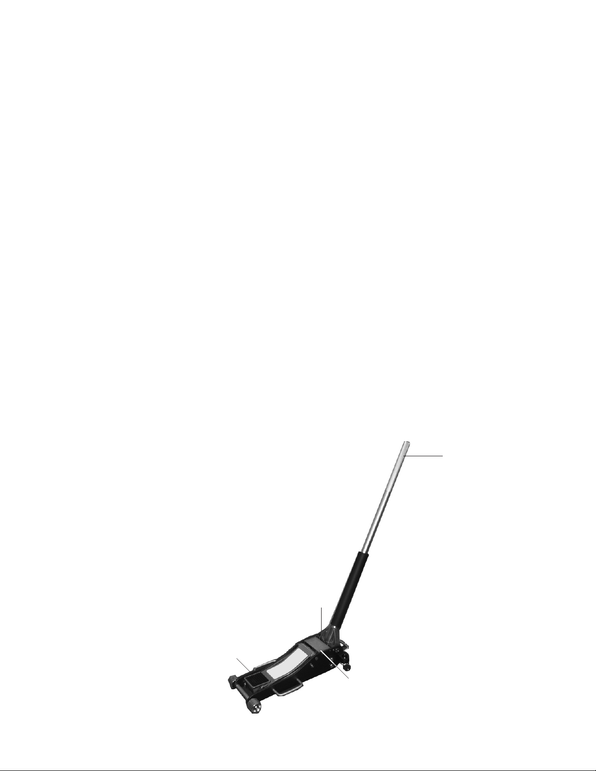
FIGURE 1
Handle Base (20)
Saddle Pad (47)
Cover Plate (19)
For technical questions, please call 1-800-444-3353
Upper Handle (23)
Page 4SKU 92782

Handle Assembly
1. Insert the Connecting Tube (27) into the Upper Handle (23) and secure it with a Hex
Bolt (22). This step may already have been done at the factory.
2. Insert the Connecting Tube (27) into the Lower Handle (21) until the button on the Con-
necting Tube (27) snaps into place. See FIGURE 2 below.
3. Slide the Handle Sleeve (48) over the Handle Assembly so that it fits on the bottom of
the Lower Handle (21). See FIGURE 2 below.
4. Loosen the knob on the side of the Handle Base (20), insert the Lower Handle (21),
and tighten the knob again.
Upper Handle (23)
FIGURE 2
Connecting Tube (27)
Lower Handle (21)
Handle Sleeve (48)
Operation
Raising the Vehicle
1. Test the Jack by placing the Saddle (46) under a stable, dead load. Turn the Handle
completely clockwise and pump the Handle up and down.
The Saddle (46) should rise and stay at that level. If it slowly goes down, lower the
load, tighten the screw in the center of the Breathing Screw (47a), and try again. If it
still goes down, the Power Unit may need to have the air purged from the system. Refer
to the Maintenance section.
2. Turn the Handle counterclockwise. The Saddle (46) should lower completely.
3. Position the Jack under the vehicle to be lifted.
Warning! The Jack and vehicle being lifted must be stable so when lifted so they
do not fall and cause personal injury. Keep spectators away from the work area.
Read the vehicle manual to find the proper lifting points for the vehicle.
4. Turn the Handle clockwise to close the release valve.
5. Pump the Handle up and down until the Saddle (46) just touches the item being lifted.
Readjust the Saddle position so that the vehicle lift point is centered on the Saddle
(46).
6. Continue pumping until the Jack is fully extended, or the vehicle is lifted to the desired
height.
7. Place jack stands (not included) under the vehicle before attempting to do any
work on, in, under, or around the vehicle.
For technical questions, please call 1-800-444-3353
Page 5SKU 92782

Operation (continued)
Lowering the Vehicle
1. First, clear any tools or equipment from under the vehicle. Make sure there are no
obstructions and that people are at a safe distance from the vehicle.
2. Position the Jack so that the Saddle (46) is at one of the recommended lifting points.
Pump the Handle until it fully engages the lifting point, then continue to pump the Jack
to the needed height above and clear of the jack stands.
3. Carefully remove the jack stands.
Note: Position yourself safely so that your body is not under any part of the
vehicle before lowering the Jack or removing the jack stands.
4. Slowly turn the Handle counterclockwise. The Saddle (46) should lower completely.
5. Pull the Jack clear of the vehicle and store in a safe place.
General Maintenance
1. Keep the Jack clean and dry.
2. Periodically lubricate the bearing and axles on the caster wheels with high quality
grease. Use a grease gun (not included) to service the Jack’s zerk fittings.
3. Have a qualified service technician periodically dismantle and lubricate the handle as-
sembly and all lift arm linkages.
4. Watch for hydraulic oil leaks. Fill oil if necessary. If leaks persist, contact a qualified
service technician.
If the Jack is not performing properly, it may have air in the hydraulic system and
need to be bled - see next page.
For technical questions, please call 1-800-444-3353
Page 6SKU 92782

Maintenance (continued)
BLEEDING AND FILLING THE JACK WITH HYDRAULIC OIL
See the Power Unit Assembly Drawing on page 11.
Filling
1. Place the Jack on a flat, level, solid surface.
2. Open the Cover Plate (19) by removing the 4 screws with a screwdriver. See FIGURE
1 on page 4.
3. Using a wrench (not included), remove the Breathing Screw (47a). See FIGURE 3
below.
4. Using a high quality hydraulic oil, fill to the top of the Cylinder Case (48a).
5. Replace and tighten the Breathing Screw (47a) and the Cover Plate (19).
WARNING!
NEVER adjust any other screws.
Doing so may cause the Jack to
FIGURE 3
Breathing
Screw (47a)
fail suddenly during operation,
causing SERIOUS PERSONAL
INJURY or DEATH.
Bleeding
1. Open access to the Cover Plate (19) as if you were filling oil (explained above), and
loosen the screw in the middle of the Breathing Screw (47a) by turning it five or six
turns.
2. Turn the Handle counterclockwise to open the release valve. Apply pressure on the
Saddle (46), holding it down. Pump the Handle up and down at least ten times. This
will bring all the air out of the system. Continue pumping until no more air bubbles appear. Turn the Handle counterclockwise to close the release valve.
3. Tighten the screw in the center of the Breathing Screw (47a).
4. Using a wrench or ratchet (neither one included), remove the Breathing Screw (47a)
and, if necessary, top off the oil reservoir with a high quality hydraulic oil. Replace the
Breathing Screw (47a) and the Cover Plate (19).
5. Test the Floor Jack. Make sure it is functioning properly before attempting to lift another
vehicle. Operate the Jack to move the Saddle (46) up and down several times to make
sure it is working properly. If not, repeat the above process.
For technical questions, please call 1-800-444-3353
Page 7SKU 92782

Jack Parts List
Part # Description Qty Part # Description Qty
1 Frame 2 25 C-ring S20 2
2 Nut M18 2 26 Spring 2
3 Front Caster 2 27 Connecting Tube 1
4 Washer 16 2 28 Eye Bolt M8x35 2
5 C-ring S16 2 29 Arm Axis 1
6 Rod 6 30 Pull Rod Axis 2
7 Nut M12 4 31 Pull Rod 2
8 Spring Washer 16 2 32 Spring Washer 16 2
9 Screw M16x30 2 33 Nut M16x1.5 2
10 Rear Wheel Set 2 34 Screw M8x20 2
11 Rear Wheel Saddle 2 35 Tapping Screw ST4.8x16 4
12 Handle Screw 2 36 Case 2
13 Inner Lock Washer 18 2 37 Inner Angle Screw M8x25 4
14 Linkage Washer 18 2 38 Limit Position Axis 1
15 Link Rod Axis 2 39 Axis 1
16 Inner Lock Washer 10 6 40 Handle Bar 2
17 Screw M10x25 4 41 C-ring S14 4
18 Rear Handle Bar 1 42 Link Rod 2
19 Cover Plate 1 43 Short Saddle Base Axis 1
20 Handle Base 1 44 Long Saddle Base Axis 1
21 Lower Handle 1 45 Lift Arm 1
22 Hex Bolt M6x12 1 46 Saddle 1
23 Upper Handle 1 47 Rubber Saddle Pad 1
24 Power Unit Assembly 1 48 Handle Sleeve 1
PLEASE READ THE FOLLOWING CAREFULLY
THE MANUFACTURER AND/OR DISTRIBUTOR HAS PROVIDED THE PARTS DIAGRAM IN THIS
MANUAL AS A REFERENCE TOOL ONLY. NEITHER THE MANUFACTURER NOR DISTRIBUTOR MAKES ANY REPRESENTATION OR WARRANTY OF ANY KIND TO THE BUYER THAT
HE OR SHE IS QUALIFIED TO MAKE ANY REPAIRS TO THE PRODUCT OR THAT HE OR SHE
IS QUALIFIED TO REPLACE ANY PARTS OF THE PRODUCT. IN FACT, THE MANUFACTURER
AND/OR DISTRIBUTOR EXPRESSLY STATES THAT ALL REPAIRS AND PARTS REPLACEMENTS
SHOULD BE UNDERTAKEN BY CERTIFIED AND LICENSED TECHNICIANS AND NOT BY THE
BUYER. THE BUYER ASSUMES ALL RISK AND LIABILITY ARISING OUT OF HIS OR HER
REPAIRS TO THE ORIGINAL PRODUCT OR REPLACEMENT PARTS THERETO, OR ARISING
OUT OF HIS OR HER INSTALLATION OF REPLACEMENT PARTS THERETO.
NOTE: Some parts are listed and shown for illustration purposes only and are not available
individually as replacement parts.
For technical questions, please call 1-800-444-3353
Page 8SKU 92782

Jack Assembly Drawing
For technical questions, please call 1-800-444-3353
Page 9SKU 92782

Hydraulic Unit Parts List - List A
Part # Description Qty Part # Description Qty
1a Ram 1 28a Washer 1
2a Ram Header 1 29a Pump Core 1
3a O-ring 1 30a Pump Case 1
4a O-ring 27.7x3.5 1 31a O-ring 2
5a C-ring 27 1 32a Back Seal 2
6a Cylinder 1 33a Press Spring 1
7a O-ring 1 34a Piston Cover 1
8a Oul Strainer 2 35a C-ring 20 1
9a Base 1 36a High Pressure Bolt 2
10a Ball 5.5 4 37a High Pressure Spring 2
11a Bolt 2 38a Bearing 9 2
12a Saftey Valve 3 39a Separator 2
13a Relief Valve Spring 1 40a Safety Valve 1
14a Regulating Bolt 2 41a Relief Valve Spring 1
15a O-ring 8.5x2.5 2 42a Bolt 1
16a Seal Bolt 2 43a Bearing 1
17a Washer 1 44a Seal Washer 1
18a Pump Core 1 45a O-ring 61.6x2.65 2
19a Pump Case 1 46a O-ring 9.5x2.65 1
20a O-ring 2 47a Breathing Screw Assy. 1
21a Back Seal 2 48a Cylinder Case 1
22a Press Spring 1 49a Pin 4x30 1
23a Piston Cover 1 50a Tank Nut 1
24a C-ring 15 1 51a O-ring 34x3.5 1
25a Discharge Valve Rod 1 52a Pin 4x28 1
26a O-ring 7.1x2.65 1 53a Block Linkage 1
27a Bearing 7 1
For technical questions, please call 1-800-444-3353
REV 02/07
Page 10SKU 92782
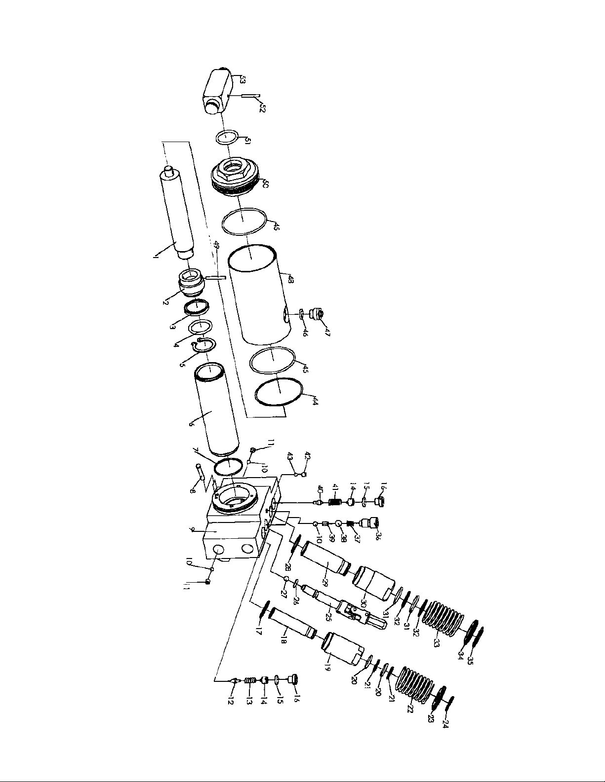
Hydraulic Unit Assembly Drawing
When ordering parts off of this diagram, always use the
suffix “a” with the part number.
For technical questions, please call 1-800-444-3353
Page 11SKU 92782

LIMITED 90 DAY WARRANTY
Harbor Freight Tools Co. makes every effort to assure that its products meet high quality
and durability standards, and warrants to the original purchaser that this product is free from
defects in materials and workmanship for the period of 90 days from the date of purchase. This
warranty does not apply to damage due directly or indirectly, to misuse, abuse, negligence or
accidents, repairs or alterations outside our facilities, criminal activity, improper installation,
normal wear and tear, or to lack of maintenance. We shall in no event be liable for death, injuries to persons or property, or for incidental, contingent, special or consequential damages
arising from the use of our product. Some states do not allow the exclusion or limitation of
incidental or consequential damages, so the above limitation of exclusion may not apply to
you. THIS WARRANTY IS EXPRESSLY IN LIEU OF ALL OTHER WARRANTIES, EXPRESS
OR IMPLIED, INCLUDING THE WARRANTIES OF MERCHANTABILITY AND FITNESS.
To take advantage of this warranty, the product or part must be returned to us with
transportation charges prepaid. Proof of purchase date and an explanation of the complaint
must accompany the merchandise. If our inspection verifies the defect, we will either repair or
replace the product at our election or we may elect to refund the purchase price if we cannot
readily and quickly provide you with a replacement. We will return repaired products at our
expense, but if we determine there is no defect, or that the defect resulted from causes not
within the scope of our warranty, then you must bear the cost of returning the product.
This warranty gives you specific legal rights and you may also have other rights which
vary from state to state.
3491 Mission Oaks Blvd. • PO Box 6009 • Camarillo, CA 93011 • (800) 444-3353
For technical questions, please call 1-800-444-3353
Page 12SKU 92782
 Loading...