


12” TILE CUTTER
Model
38173
SET UP AND OPERATING INSTRUCTIONS
Visit our website at: http://www.harborfreight.com
Read this material before using this product.
Failure to do so can result in serious injury.
SAVE THIS MANUAL.
Copyright© 1998 by Harbor Freight Tools®. All rights reserved. No portion of this manual or any artwork contained
herein may be reproduced in any shape or form without the express written consent of Harbor Freight Tools.
Diagrams within this manual may not be drawn proportionally. Due to continuing improvements, actual product may
differ slightly from the product described herein. Tools required for assembly and service may not be included.
Revised Manual 10c
For technical questions or replacement parts, please call 1-800-444-3353.

Thank you for choosing a Harbor Freight Tools product. For future reference, please complete
the owner’s record below:
Model:____________________ Purchase Date:______________________
Save the receipt, warranty and these instructions. It is important that you read this entire instruction sheet to become familiar with the unit before you begin using it.
Technical Specications
Cutter Capacity: Cuts Tile Up To 12” Long, 1/2” Deep
Includes Adjustable Fence with Scale
Dimensions: 19-3/4” L, 6-3/8” W, 4-1/2” H
Cutting Pad: 13-1/4” Long
Unpacking
Unpack and check the contents. If any parts are missing, please call Harbor Freight Tools at
1-800-444-3353. Be sure you have all the parts described in the parts listing on page 5.
Assembly
It is important that you read the entire manual to become familiar with the unit before you begin
assembly. Letter designations shown below identify the parts-see Page 5. The only assembly
required involves inserting the threaded end of the Lever Rod (A) into the Sliding Frame (B).
Screw the handle clockwise until it is tightly in place. The Tile Cutter is now ready to be used.
#38173 Page 2

WARNING:
When using electric tools, machines or 1.
equipment, basic safety precautions should
always be followed to reduce the risk of re,
electric shock, and personal injury.
Keep work area clean. Cluttered areas 2.
invite injuries.
Consider work area conditions. Do not 3.
use machines or power tools in damp,
wet, or poorly lit locations. Do not expose
equipment to rain. Keep work area well
lit. Do not use tools in the presence of
ammable gases or liquids.
Keep children away. All children should be 4.
kept away from the work area.
Guard against electric shock. Prevent body 5.
contact with grounded surfaces such as
pipes, radiators, ranges, and refrigerator
enclosures.
Stay alert. Never operate equipment if you 6.
are tired.
Do not operate the product if under the 7.
inuence of alcohol or drugs. Read
warning labels on prescriptions to
determine if your judgment or reexes
might be impaired.
Do not wear loose clothing or jewelry as 8.
they can be caught in moving parts.
Wear restrictive hair covering to contain 9.
long hair.
Use eye and ear protection. Always wear:10.
-ANSI approved chemical splash goggles
when working with chemicals.
-ANSI approved impact safety goggles at
other times.
-ANSI approved dust mask or respirator
when working around metal, wood, and
chemical dusts and mists.
-A full face shield if you are producing metal
or wood lings.
Keep proper footing and balance at all 11.
times.
Do not reach over or across running 12.
machines.
Always check that adjusting keys and 13.
wrenches are removed from the tool or
machine work surface before plugging it in.
Do not carry any tool with your nger on 14.
either the start button or trigger.
When servicing, use only identical 15.
replacement parts.
Check for damaged parts. Before using 16.
any tool, any part that appears damaged
should be carefully checked to determine that
it will operate properly and perform its intended
function.
Check for alignment and binding of all moving 17.
parts, broken parts or mounting xtures and any
other condition that may affect proper operation.
Any part that is damaged should be properly
repaired or replaced by a qualied technician.
Never force the tool or attachment to do the 18.
work of a larger industrial tool. It is designed to
do the job better and more safely at the rate for
which it was intended.
IF THERE IS ANY QUESTION ABOUT A CONDITION
BEING SAFE OR UNSAFE, DO NOT USE THE
TOOL.
OPERATING THE TILE CUTTER
Refer to the Parts Diagram and Part Number Listing
while performing the following steps.
To make straight cuts on tile, perfom the following
steps:
Mark with a soft carpenter’s pencil the location 1.
where the tile cut is planned. Place the tile
against Try Square (L), with the glazed side
up. The pencil line should be straight under the
Cutting Wheel (C).
Hold the tile rmly and cut with the Cutting 2.
Wheel a number of times across the pencil line.
Raise the Lever Rod, and position the tile so that 3.
the front edge of the pencil line is lined up with
the edge of the Breaking Part (D). Press down
rmly on the Lever Rod to split the tile along the
pencil line.
Note: The cutting action occurs by moving the
Sliding Frame from the back to the front each time
and pressing down on the Lever Rod slightly. At the
end of the cutting motion, raise the Lever Rod and
Breaking Part, and move it backwards. Repeat this
cutting action a number of times, depending on the
thickness of the tile, until a scored line appears.
#38173 Page 3
MAINTENANCE
The Tile Cutter requires little regular maintenance.
Clean the Tile Cutter after using by removing tile debris.1.
Lubricate the Guide Track (F) periodically.2.
Store and cover the Tile Cutter when not in use. Always store in a dry location.3.
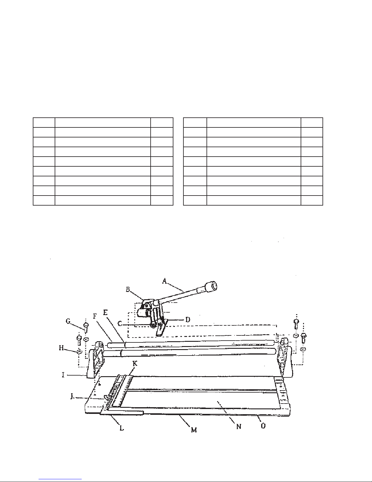
PARTS LIST
Part Description QTY Part Description QTY
A Lever Rod 1 I Guide Track Holders 2
B Sliding Frame 1 J Wing Nut 1
C Cutting Wheel 1 K Graduated Ruler 1
D Breaking Part 1 L Try Square 1
E O-Ring 2 M Bottom Board 1
F Guide Track 2 N Cushions-EVA 2
G Hexagon Hex Bolts 4 O Rubber Slip 2
H Washers 4
DIAGRAM
#38173 Page 4
 Loading...