

Page 1
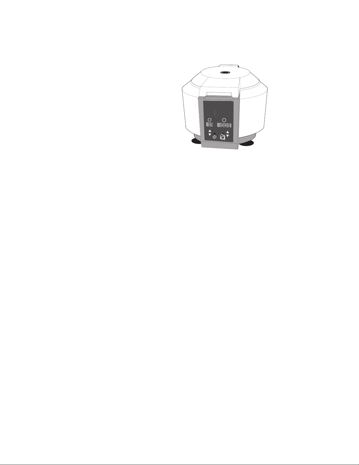
INSTRUCTION
MANUAL
IM-426
Revision 8
IEC Centra
INTERNATIONAL EQUIPMENT COMPANY
¨
CL2
Centra-CL2
Centrifuge
Cat. No. 426 -- For 120 VAC, 50/60 Hz
Cat. No. 427 -- For 240 VAC, 50/60 Hz
Page 2

Table of Contents
1 INTRODUCTION.............................................................................................. 2
2 INSTALLATION................................................................................................ 3
3 OPERATION .................................................................................................... 4
3.1 Warnings and Cautions ............................................................................ 4
3.2 Opening The Cover .................................................................................. 4
3.3 Rotor Installation...................................................................................... 5
3.4 Starting And Stopping A Run.................................................................... 5
3.5 Rotor Removal.......................................................................................... 5
3.6 Balance..................................................................................................... 6
4 APPLICATIONS ............................................................................................... 7
4.1 Speed And Force Tables .......................................................................... 8
4.2 Derating Table for Dense Samples........................................................... 10
4.3 Chemical Resistance Table ...................................................................... 11
4.4 Compatible Processes For Decontamination............................................ 12
4.5 Nomograph ............................................................................................... 13
5 MAINTENANCE ............................................................................................... 14
5.1 Cleaning.................................................................................................... 14
5.2 Brush Replacement .................................................................................. 15
5.3 Fuse Replacement.................................................................................... 16
5.4 Cover Interlock Bypass............................................................................. 16
5.5 Calibration................................................................................................. 16
5.6 Power Cord Replacement......................................................................... 16
5.7 Warranty ................................................................................................... 17
5.8 Condition of Returned Equipment............................................................. 17
6 SPECIFICATIONS ........................................................................................... 18
7 SERVICE ......................................................................................................... 19
7.1 Warning Messages and Error Codes....................................................... 19
7.2 General ..................................................................................................... 19
7.3 Disassembly For Service .......................................................................... 20
7.4 Interlock .................................................................................................... 20
7.5 Timer PCB ................................................................................................ 21
7.6 Motor......................................................................................................... 21
7.7 Interlock PCB............................................................................................ 22
8 DRAWINGS ..................................................................................................... 23
IMPORTANT
This manual may not contain information on all changes that have occurred to the subject instrument since
the manual issue date. It was prepared for use by IEC authorized factory-trained service or dealer
personnel who are kept current through a program of service letters and bulletins and training seminars.
This manual contains
personal injury. It also contains
centrifuge or accessory equipment. Read this manual thoroughly before operating or servicing this
centrifuge.
Centra-CL2 Instruction Manual
warnings
against operating procedures which could result in an accident and/or
cautions
against procedures which could result in damage to your
1
Page 3

1 INTRODUCTION
The IEC Centra-CL2 is a compact benchtop centrifuge designed for
multipurpose use in medical, industrial, and scientific laboratories.
There are two models:
• Cat. No. 426 for 120 V, 50/60 Hz
• Cat. No. 427 for 240 V, 50/60 Hz
The Centra-CL2 accommodates a wide variety of rotors, including fixed angle
and horizontal (swinging bucket). IEC AeroCarriers™ provide aerosol
containment along with autoclaveability. The CL2 can handle up to 300 ml
(801 rotor), and reach maximum speeds of up to 8500 rpm (841 fixed angle
rotor) and 3900 rpm (236 horizontal rotor).
Other important features of the CL2 are a cover interlock for safety, and a
'glove-friendly' membrane control panel with digital speed and time displays.
An 'At Speed' timer mode allowing for accurate separations, and a continuous
'hold' mode are also featured.
2
Centra-CL2 Instruction Manual
Page 4

2 INSTALLATION
After unpacking, place the unit on a clean, level surface. The
surface must be level to ensure quiet, vibration-free operation. A
rigid, stable location is important since an improperly loaded unit can
vibrate or even move. Allow a space of 3 in. (7.6 cm) on each side and 4 in.
(10.2 cm) in the rear of the unit for ventilation. Ensure that the suction cup feet
grip the surface firmly.
Using a voltmeter, measure the line voltage to ensure it is within the limits for
your model. For Cat. No. 426 the line voltage should be between 108 and 132
VAC. For Cat. No. 427 the line voltage should be between 216 and 264 VAC.
Variations in line voltage or frequency will affect the unit’s speed and
acceleration.
Before moving, unplug the centrifuge and remove all accessories and the rotor.
Clearance Envelope International Electrotechnical Commission standard 1010 part 2-20 limits
the permitted movement of a laboratory centrifuge to 300mm in the event of a
disruption. The user should therefore mark the clearance envelope boundary
around the centrifuge, or laboratory management procedures should require
that no person or any hazardous materials are within such a boundary while
the centrifuge is operating.
Centra-CL2 Instruction Manual
3
Page 5

3.1 Warnings and Cautions
Warnings To Avoid Electric Shock:
• Plug the power cord into a grounded outlet.
• Never remove the grounding prong from the power plug, or use any
adapter which does not complete the grounding circuit.
3 OPERATION
• Always unplug the power cord before attempting to clean or service
Cautions
• DO NOT exceed maximum rated speed for each rotor/accessory
• Samples of specific gravity higher than 1.2 require the maximum
• Ensure that loads are properly balanced around the rotor to minimize
• Do not block the vents, otherwise, airflow will be restricted.
• Be sure the rotor and accessories are properly installed before
3.2 Opening The Cover
Once the red light over the STOP button is steadily illuminated (no longer
flashing) pressing the COVER OPEN button on the control panel will release
STOP/COVER
OPEN
the interlock, allowing the cover to be opened.
the centrifuge.
combination. Maximum speeds can be found in Section 4.1 Speed
And Force Tables. All IEC rotors and accessories are stamped with
their cat. no. for easy identification.
speed to be derated.
vibration. All IEC accessories are stamped with their weight for easy
balancing.
attempting to start a run.
4
Centra-CL2 Instruction Manual
Page 6
3.3 Rotor Installation
When the unit has power, the red light over the STOP button is illuminated.
This is also an indication that the rotor is stopped and the cover can be
opened. Push the COVER OPEN lever to the right and lift the cover. Lower
the rotor straight onto the shaft. Screw the knurled metal locking nut
(clockwise) onto the shaft to hold the rotor down (on some rotors, you must
remove any sample tubes first.). Tighten the nut with your fingers; do not use a
tool.
Rotors with or without a keyway can be used on the Centra-CL2 since there is
no key on the shaft.
3. 4 Starting And Stopping A Run
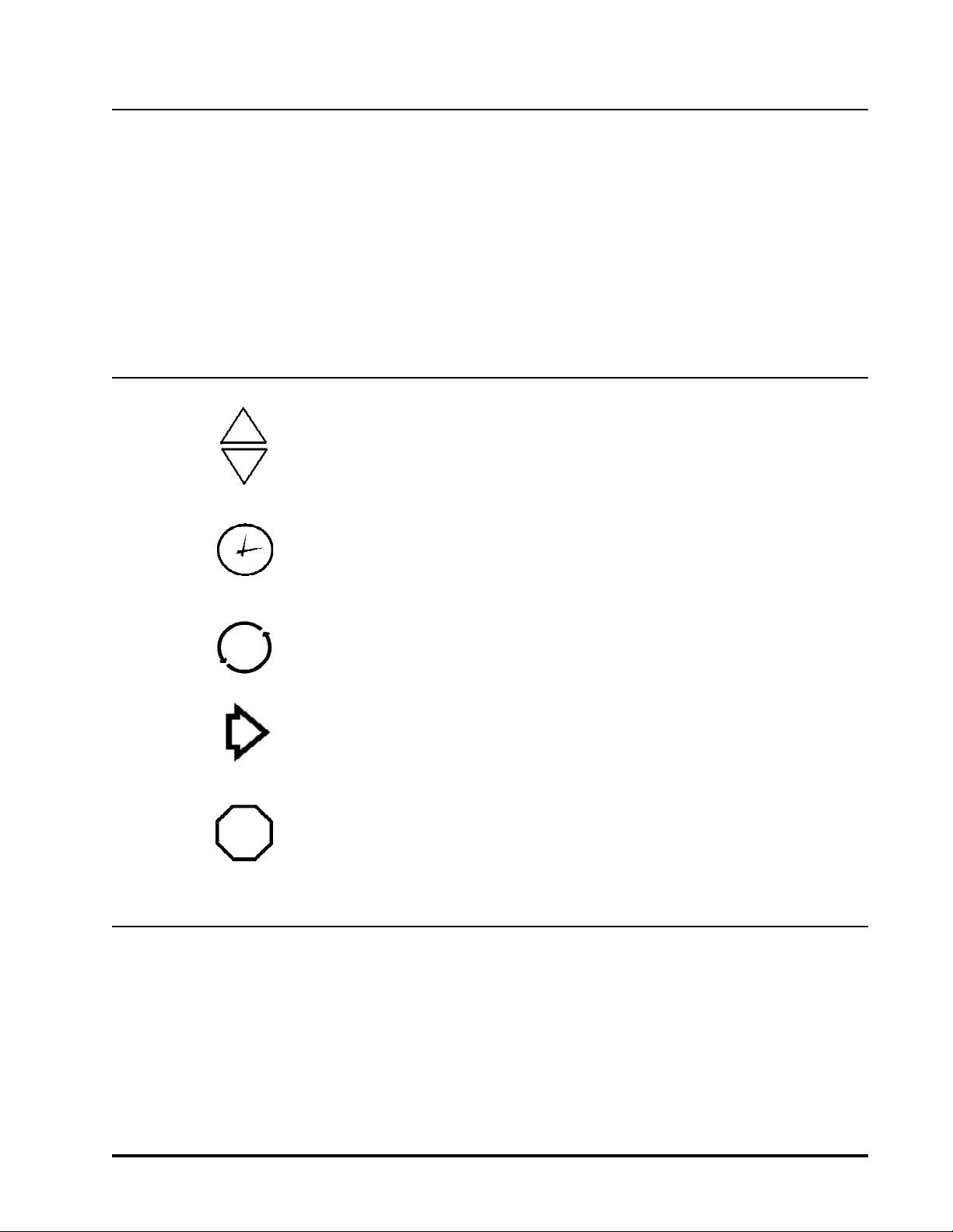
To start a run, use the ARROW buttons to set the desired run time (0 to 30
minutes) in the TIME display, and the desired rpm in the SPEED display.
Press the START button. The green light under the START button will
illuminate, and the time display will begin counting down. The actual speed is
ARROW
displayed in the SPEED display. The centrifuge will run for the set duration
and decelerate to a stop. To terminate a run before time expires, press the
STOP button. The red light over the STOP button illuminates when STOP is
pressed or time expires, and it flashes until the rotor comes to a stop.
TIME
SPEED
START
STOP
3.5 Rotor Removal
Note: The cover may be opened when the rotor speed is below 20 RPM.
The time and speed settings cannot be changed during a run. A new run
cannot be started until the rotor has come to a complete stop.
For infinite spins (hold mode), use the arrow keys to scroll up past 30 minutes.
The word 'HOLD' appears in the display. Pressing the START button will begin
a run which can only be terminated by pressing the STOP button. In the hold
mode, the timer counts up.
To select the timing mode, use the arrow buttons to scroll down past 0
seconds. The letters 'Spd' or 'Acc' will appear. Press the arrow buttons to
toggle between the two timing modes. 'Spd' is the 'At Speed' timing mode
where the timer starts counting down when rotor reaches 95% of set speed.
'Acc' is the normal timing mode where the timer begins to count down as soon
as the run button is pressed.
To remove a rotor, first remove any sample tubes, shields, and other
accessories from the rotor. Next, unscrew (counterclockwise) approximately
one full turn the knurled locking nut. Then place both thumbs on the knurled
locking nut and grip the rotor with the fingers. Push your thumbs down and at
the same time pull the rotor up with your fingers. This should dislodge the rotor
from the shaft. If unsuccessful, lightly tap the knurled metal locking nut with a
rubber/plastic mallet or other similar object. The nut and the rotor can now be
removed from the shaft.
Centra-CL2 Instruction Manual
5
Page 7
3.6 Balance
A balanced load is essential with all centrifuges. An unbalanced load
produces vibration and can damage the unit. A 2-gram load imbalance, at a
speed of 4600 rpm, imparts force equivalent to 9.1 kg at rest (20 pounds).
Therefore, always ensure that the rotor is loaded symmetrically and with a full
(or paired) set of tubes. Tube adapters should also be installed
symmetrically.
IEC rotors are dynamically balanced at the factory. IEC matches removable
parts (trunnion rings, shields, cups and carriers) to within 1 gram and stamps
the weight on each piece. Check these markings whenever you interchange
parts, to ensure that opposite parts are matched. Ensure that the total weight
of samples and removable parts loaded in opposing positions are equal in
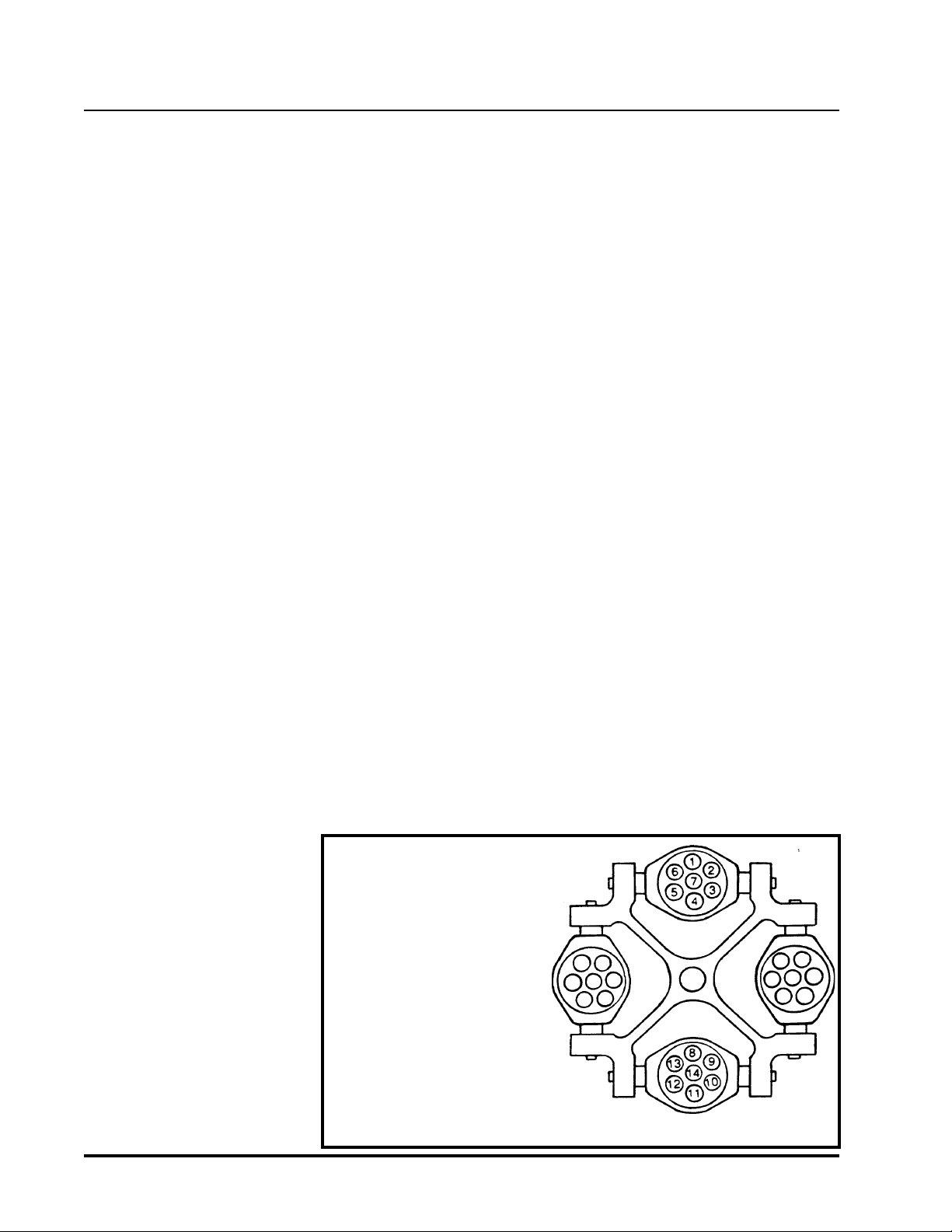
weight to within 1 gram. The position numbers, present on many rotors and
adapters, identify opposing tube positions.
To obtain good dynamic balance, the opposite loads must not only be equal in
mass, but must also have the same center of gravity. Opposing containers
must be alike in shape, thickness, and distribution of glass or plastic. This is
especially important for large containers.
Tubes loaded into swinging bucket rotors must likewise be symmetric around
the axis of rotation. Verify this by rotating the entire rotor 180° by hand: the
loads should be in the same apparent positions (not in the mirror image). In
addition, the loads within each bucket must also be symmetric around the
bucket’s pivot axis. Verify this by ensuring that each bucket is loaded so that
it does not tilt from the vertical when the rotor is at rest. Maintaining balance
within each bucket ensures that the bucket and the tubes swing out to
horizontal when the rotor reaches operating speed, applying centrifugal force
toward the bottom of the tubes. Failure to achieve full swing-out causes
vibration and premature wear.
Samples of different specific gravities can be processed in the same run,
provided that the samples of a given type are balanced around the rotor as
though they were the only ones in the rotor.
For example, load tubes in the
following manner:
1. Load four tubes.
Positions 3, 6, 10, 13
or 2,5,9,12
or 1,4,8,11
2. Load six tubes.
Positions 6,7,3,13,14,10
or 5,7,2,12,14,9
or 1,7,4,8,14,11
3. Load an odd number of tubes.
Not recommended (unless a
dummy tube is used for balance.)
6
Centra-CL2 Instruction Manual
Page 8

4 APPLICATIONS
This section describes the use of specific rotors and accessories. More
detailed information is often shipped with the rotor or accessory itself. This
section contains four reference tables:
4.1 Speed And Force Table
4.2 Derating Table for Dense Samples
4.3 Chemical Resistance Table
4.4 Decontamination Table
4.5 Nomograph
Relative centrifugal force (RCF or G-force) at a given speed varies with the
rotor, and with the length of the sample tube, because the distance of the
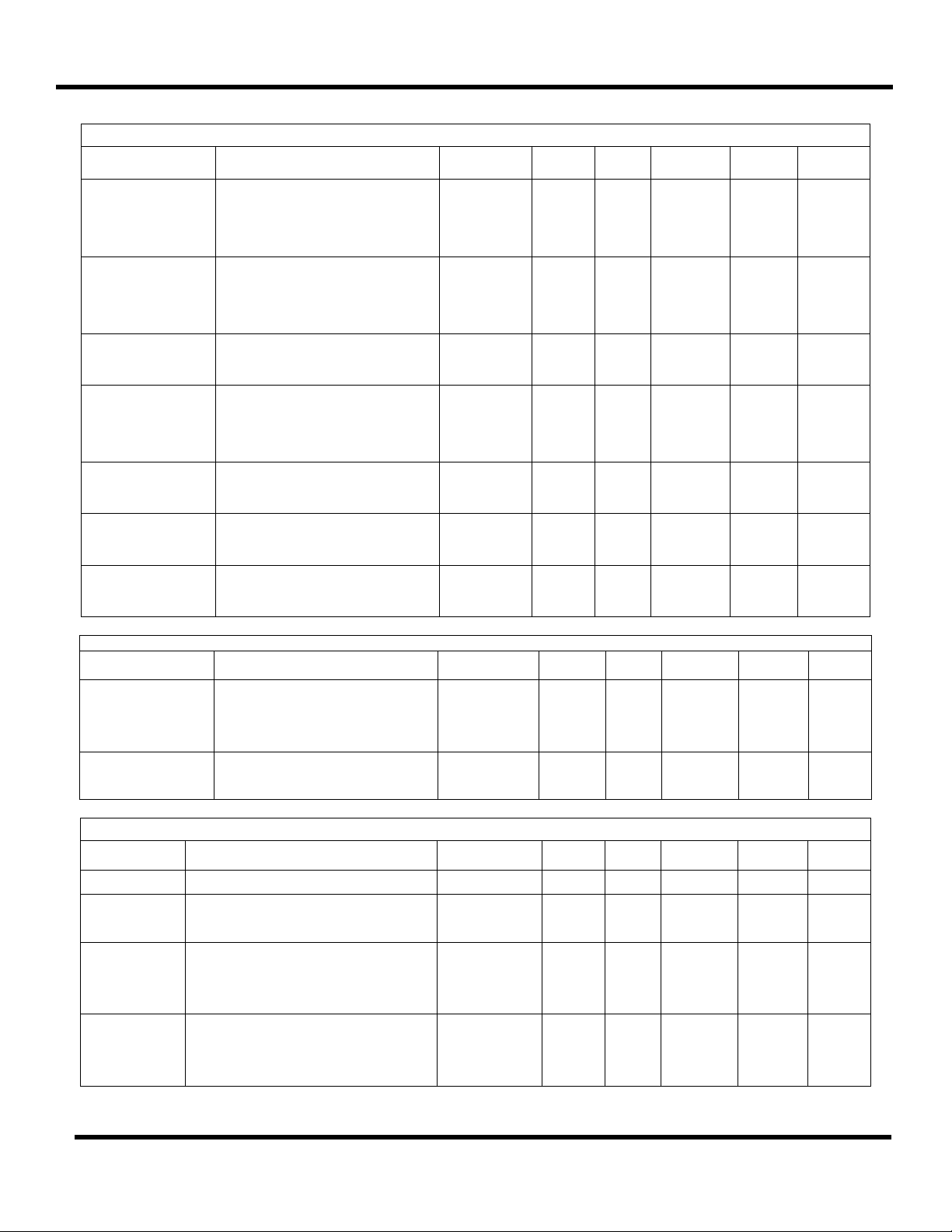
tube’s tip from the center of rotation is different. The Speed and Force Table
indicates the maximum speed and RCF the Centra-CL2 can achieve with
various rotor/accessory combinations.
The Derating Table specifies reductions in rpm when spinning samples with
specific gravity above 1.2.
Misapplication of any tube can cause tube rupture. To avoid this, compare the
G forces specified in the Speed and Force Table with the ratings for the tubes
you are using. If the tubes are not rated for the force the centrifuge will apply,
reduce the speed to the G force limit of your tubes.
Your IEC centrifuge is made of materials designed to resist attack from most
laboratory chemicals. The interior of the rotor chamber is Painted steel.
Rotors and accessories placed in the chamber are made of a variety of
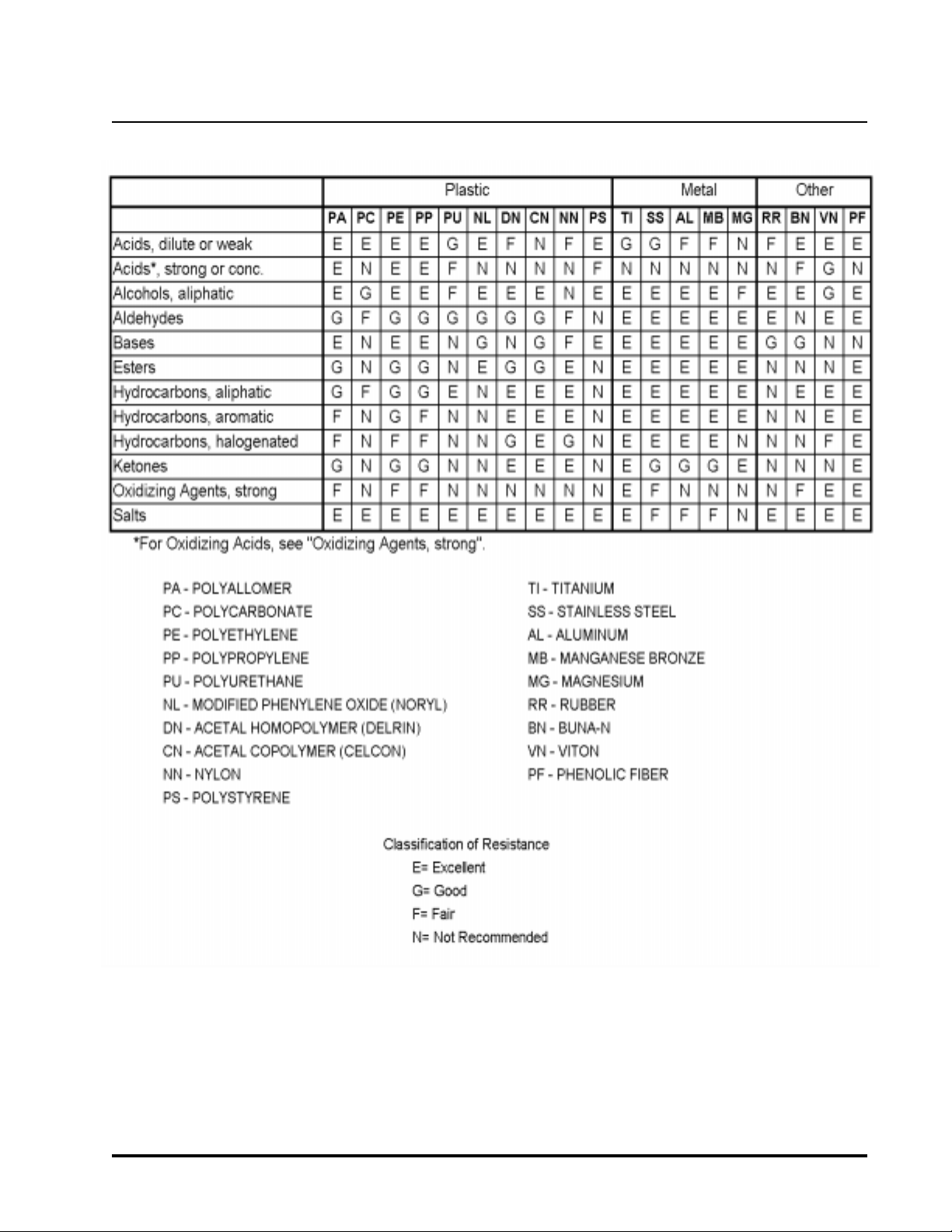
materials, including aluminum and polypropylene. The Chemical Resistance
Table shows the suitability of each material with different classes of reagents.
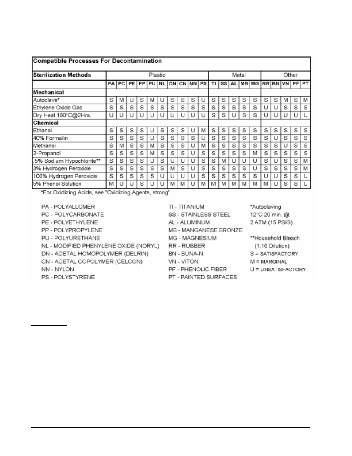
The Decontamination Table lists compatible methods of decontamination
which may be used on the IEC Centra-CL2 centrifuge.
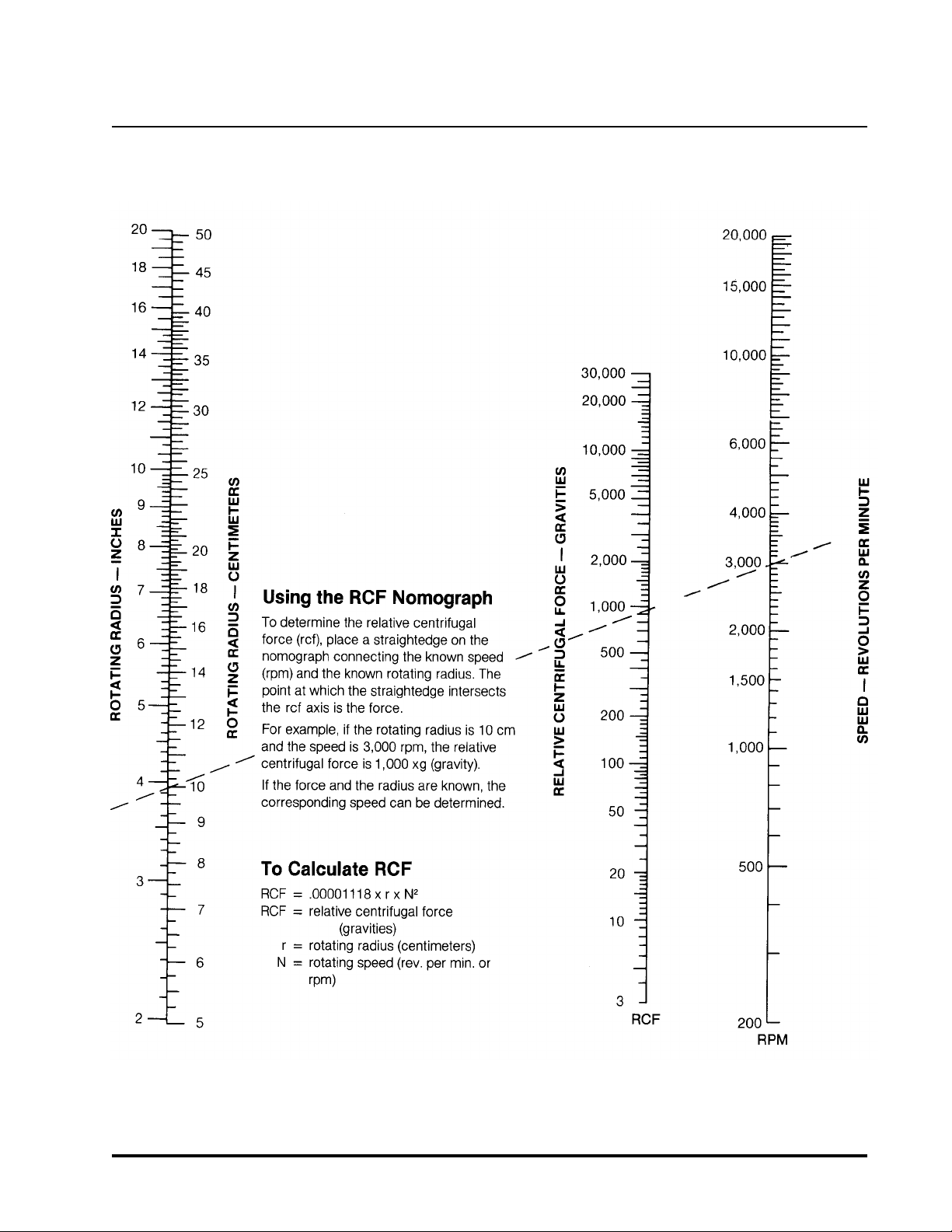
The Nomograph provides an easy method of converting RPM to RCF (or xg).
Section 5.1 describes how to clean and remove corrosion from the chamber,
rotors, and accessories. Follow these instructions, and clean spills promptly,
to minimize the effects of corrosive chemicals, before any resulting chemical
attack requires more expensive repair. Replace metal locking nut, rotors, or
accessories if they become cracked, deformed, or gouged.
Centra-CL2 Instruction Manual
7
Page 9
4.1 Speed And Force Tables
Rotor 215: 4-Place Swinging Bucket Rotor
Tube
No. x Vol. Tube
8x50ml
8x50ml
8x15ml
4x50ml
4x50ml
4x15ml
4x50ml sealed
4x15ml sealed
4x15ml sealed
4x10-15ml sealed
4x7ml sealed
12x10ml
12x7ml
16x7ml
16x5ml
20x5ml
20x3ml
Falcon/Corning Conical plastic
Corning 8300-50 conical glass
Falcon/Corning Conical plastic
Falcon/Corning Conical plastic
Corning 8300-50 conical glass
Falcon/Corning Conical plastic
Falcon/Corning Conical plastic
Falcon/Corning Conical plastic
Falcon/Corning
Vacutainer 16x100-125mm
Vacutainer 13x100mm
16x100mm
16x75mm
13x100mm
13x75mm
12x75mm
10x75mm
Maximum
RPM / RCF Radius
3100 / 1510
3100 / 1510
3100 / 1510
3350 / 1750
3350 / 1750
3350 / 1750
3175 / 1750
3350 / 1750
3175 / 1710
3176 / 1710
3175 / 1710
3450 / 1725
3450 / 1725
3450 / 1700
3450 / 1700
4000 / 1975
4000 / 1975
14.1
14.1
14.1
13.9
13.9
13.9
15.4
13.9
15.2
15.2
15.2
12.9
12.9
12.8
12.8
11.1
11.1
Tr.
Ring
4x326
4x326
4x326
4x325
4x325
4x325
4x350
4x325
4x350
4x350
4x350
4x366
4x366
4x366
4x366
4x366
4x366
Shield or
Carrier Adapter Cushion
8x320
8x320
8x320
4x320
4x320
4x320
4x323
4x320
4x7323
4x7323
4x7323
4x10¹³
4x10¹³
4x10¹⁸
4x10¹⁸
4x369
4x369
-
-
8x1106
-
-
4x1106
-
4x1106
1106
1106
4x1105
-
-
-
-
-
-
8x315
571
570
4x315
571
570
315
4x668
4x571
4x668
4x571
570
570
667
667
567
567
Rotor 221: 6-Place Fixed Trunnion Swinging Bucket
Tube
No. x Vol. Tube
6x15ml
6x12.5ml
6x12ml
6x10ml
6x10ml
Falcon/Corning
Kimble 45170-125
IEC 1629, 1649
Corning 8080-10
IEC 2046, 2067
Maximum
RPM / RCF Radius
3100 / 1650
3100 / 1650
3100 / 1570
3500 / 1890
3500 / 1780
15.4
15.4
14.6
13.8
13.0
Tr.
Ring
Fixed
Fixed
Fixed
Fixed
Fixed
Shield or
Carrier Adapter Cushion
6x303
6x303
6x303
6x356
6x356
-
-
-
-
-
Rotor 236: 4-Place Aerocarrier Horizontal Swing-Out Rotor
Tube
No. x Vol. Tube
4x50ml Falcon/Corning 3400 / 1950 15.0 Fixed 4x2091S - -
8x15ml
8x10ml
16x10ml
16x7ml
16x7ml
28x7ml
28x5ml
28x5ml
Falcon/Corning
Kova/UriSystem
Vacutainer 16x100mm
Vacutainer 13x100mm
Hemogard Vacutainer 13x100mm
Vacutainer 16x75mm
Vacutainer 13x75mm
Hemogard Vacutainer 13x75mm
Maximum
RPM / RCF Radius
3400 / 2000
3400 / 2000
3700 / 2200
3701 / 2200
3700 / 200
3900 / 2150
3901 / 2150
3900 / 2150
15.5
15.5
14.3
14.3
14.3
12.7
12.7
12.7
Tr.
Ring
Fixed
Fixed
Fixed
Fixed
Fixed
Fixed
Fixed
Fixed
Shield or
Carrier Adapter Cushion
4x2092S
4x2092S
4x2093S
4x2093S
4x2093S
4x2094S
4x2094S
4x2094S
-
-
-
-
-
-
-
-
668
668
570
668
570
-
-
-
-
-
-
-
-
8 Centra-CL2 Instruction Manual
Page 10
Rotor 801: 6-Place 45 Degree Fixed Angle Rotor
Tube
No. x Vol. Tube
6x50ml
6x50ml
6x15ml
6x50ml
6x50ml
6x15ml
Falcon/Corning Conical plastic
Corning 8300-50 conical glass
Falcon/Corning Conical plastic
Falcon/Corning Conical plastic
Corning 8300-50 conical glass
Falcon/Corning Conical plastic
Maximum
RPM / RCF Radius
3900 / 2050
3900 / 2050
3900 / 2050
4500 / 2450
4500 / 2450
4500 / 2450
12.1
12.1
12.1
10.8
10.8
10.8
Tr.
Ring Shield Adapter Cushion
-
-
-
-
-
-
6x305
6x305
6x305
6x320
6x320
6x320
-
-
6x1106
-
-
6x1106
Rotor 804S: 4-Place 40 Degree Fixed Angle Rotor
Tube
No. x Vol. Tube
4x50ml
4x50ml
4x15ml
4x60ml Corning 8540-60 2500 / 1000 14.3 - 4x341 - 572
Falcon/Corning Conical plastic
Corning 8300-50 conical glass
Falcon/Corning Conical plastic
Maximum
RPM / RCF Radius
4200 / 2270
4200 / 2270
4200 / 2270
11.5
11.5
11.5
Tr.
Ring Shield Adapter Cushion
-
-
-
323
323
323
-
-
6x1106
Rotor 809: 12-Place 45 Degree Fixed Angle Rotor
Tube
No. x Vol. Tube
12x15ml
12x15ml
126xDevice
12x10ml
12xDevice
12x10ml
12x10ml
Falcon/Corning conical plastic
Corning 8080-15 conical glass
Amicon Filtration Device
Corning 8080-10
Filtron or Millipore Devices
Corning 8080-10
17x102mm
Maximum
RPM / RCF Radius
3800 / 2150
3800 / 2050
3800 / 2050
4500 / 2310
4500 / 2490
4100 / 2270
4100 / 2120
13.3
12.7
13.4
10.2
11.0
12.1
11.3
Tr.
Ring Shield Adapter Cushion
-
-
-
-
-
-
-
302
302
302
12x356
12x356
12x303
12x303
-
-
-
-
-
-
-
6x315
571
570
6x315
571
570
315
571
570
668
570
-
570
-
12x668
570
Rotor 841: 12-Place 45 Degree Fixed Angle Rotor
Tube
No. x Vol. Tube
12x1.5-2.0ml
12x0.7ml
12x0.5ml
12x0.4ml
12x0.25ml
microtubes
microtubes
microtubes
microtubes
microtubes
Maximum
RPM / RCF Radius
8500 / 4680
8500 / 4770
8500 / 3960
8500 / 4680
8500 / 3630
5.8
5.9
4.9
5.8
4.5
Tr.
Ring Shield Adapter Cushion
-
-
-
-
-
-
-
-
-
-
-
5763
5763
5764
5764
-
-
-
-
-
Centra-CL2 Instruction Manual 9
Page 11

4.2 Derating Table for Dense Samples
The Speed and Force Table lists the Maximum speed for each rotor/
accessory combination in the Centra-CL2. IEC guarantees that the units can
achieve these speeds when used at nominal voltage.
These speeds are guaranteed only with samples whose specific gravity is not
greater than:
1.2 for swinging bucket rotors
1.5 for angle rotors
For denser samples, the maximum guaranteed speed is reduced (derated) by
a factor from the table below:
Specific Gravity Swinging Bucket Fixed Angle
1.2 1 1
1.3 .960 1
1.4 .925 1
1.5 .894 1
1.6 .866 .967
1.7 .839 .939
1.8 .816 .912
1.9 .794 .888
2.0 .774 .866
2.1 .755 .844
2.2 .738 .825
2.3 .721 .807
2.4 .707 .790
2.5 .692 .774
2.6 .678 .758
2.7 .666 .744
2.8 .654 .731
2.9 .642 .719
3.0 .632 .707
Derating Factor for:
10
Example. An angle rotor rated for 5,000 rpm, used with samples with a
specific gravity of 1.6, should not be spun faster than (5,000 x .967 =) 4,835
rpm.
Specific gravities greater than 3.0. This table is based on the formula:
Ö(s0/sa)
...where s0 is the maximum specific gravity allowed before derating (1.2 or
1.5, depending on the type of rotor), and sa is the actual specific gravity of the
sample in question. You can use the same formula to compute derating
factors for specific gravities greater than 3.0.
Centra-CL2 Instruction Manual
Page 12
4.3 Chemical Resistance Table
Centra-CL2 Instruction Manual
11
Page 13
4.4 Compatible Processes For Decontamination
WARNING:
This chart describes the material compatibility of various sterilization methods. It does not specify
the adequacy of sterilization. Refer to section 4.3 Chemical Resistance Table for material
compatibility during centrifugation.
12
Centra-CL2 Instruction Manual
Page 14
4.5 Nomograph
Centra-CL2 Instruction Manual
13
Page 15

5.1 Cleaning
Corrosion IEC manufactures and finishes rotors and structural accessories to give
5 MAINTENANCE
Keep your centrifuge clean to ensure good operation and to extend its life.
Clean the entire sample chamber, rotor, and lid at the end of each workday,
and also right after any spill.
To clean the sample chamber, use a damp sponge, warm water, and a mild
liquid detergent suitable for washing dishes by hand, such as Ivory® liquid.
Do not use caustic detergents or detergents that contain chlorine ions, since
these attack metals. Remove stubborn stains with a plastic scrub pad. Do
not use steel wool, wire brushes, abrasives, or sandpaper, since they create
corrosion sites. Never pour water directly into the sample chamber. Scrub the
rotor’s tube cavities with a stiff test-tube brush that has end bristles and a
nonmetallic tip. After cleaning any part, dry it properly, preferably using a
clean, absorbent towel.
maximum resistance to corrosion. However, maximum equipment life requires
that you continually inspect the rotor cavities for corrosion, especially after
using chloride ion solutions, such as sodium chloride (saline), and sodium
hypochlorite (household bleach). These solutions attack most metals. Clean
the rotor, rotor chamber, and accessories (particularly the sample
compartments and bucket cups) thoroughly after each such use. Inspect all
surfaces under bright light for corrosion; small crevices will grow deeper and
cause failure.
If you see any corrosion, remove it immediately as follows:
1. Follow the cleaning procedure at the start of this section. Soak the
part in the mild hand-dishwashing detergent. Scrub the part
thoroughly with a stiff test-tube brush having end bristles and a nonmetallic tip.
2. Soak the part again in clear warm water for at least an hour.
3. Rinse the part thoroughly in warm water first, then in distilled water.
4. Dry the part thoroughly with a clean, absorbent cloth.
5. If this procedure does not remove the corrosion, discontinue use of
the part.
Storage Store parts on a soft surface to avoid damaging finished surfaces. Rotors
and other parts should be clean and dry for storage. Store them open to the
atmosphere, not in a plastic bag, so that any residual moisture will evaporate.
The parts should face downward to avoid retaining moisture in the cavities.
14
Centra-CL2 Instruction Manual
Page 16

Decontamination Decontamination is called for if tube breakage occurs and infectious,
pathogenic, or radioactive material is released into the unit. Some rotors or
accessories totally contain the sample tubes. In this case, spillage is usually
confined, and it may be sufficient to decontaminate only the rotor or
accessory.
The Decontamination Table lists the sensitivity of various materials to
common sterilization procedures. When using a 1-to-10 dilution of household
bleach (sodium hypochlorite) to decontaminate metal rotors or accessories,
follow decontamination by the corrosion cleaning procedure given earlier, since
chloride ions attack most metals.
Always decontaminate for the minimum recommended time. If you observe
corrosion, remove it as described earlier, discontinue use of the sterilization
method, and use an alternate decontamination procedure.
Sterilization of polypropylene rotors can be done by autoclaving. Remove any
sample tubes before autoclaving, unless they are completely full of sample, or
remove caps, stoppers, and other tube closures, before autoclaving to keep
the tubes from collapsing under pressure. Autoclave the rotor and
accessories at 121° C @ 15 psig for 20 minutes. Do not stack polypropylene
rotors during autoclaving. After the rotor is cool to the touch, do a normal
cleaning operation as described above.
Repeated autoclaving will seriously degrade the performance of polycarbonate
materials.
5.2 Brush Replacement
Refer servicing to qualified personnel only. Brush replacement is required
when the length of the brush not including the spring is less than 1/4 inch long.
Order additional sets as IEC Part Number 1780A.
WARNING DISCONNECT POWER CORD BEFORE REMOVING THE
First, remove all rotor and accessories from the chamber. Gently tilt the unit
onto its side and remove the four screws which secure the baseplate. The
brush caps are located on either side of the motor housing. Unscrew each cap
with your fingers (or use a small flat screwdriver) and remove the brushes.
There are two black caps which can be removed from the housing to allow use
of a large screwdriver. Measure the length of the brushes and replace both
brushes if either one is less than 1/4 of an inch long. Be sure to reinstall all
parts removed.
It is important to check the brushes periodically since damage to the motor
can occur if the brush is allowed to wear down to the spring.
BRUSHES.
Centra-CL2 Instruction Manual
15
Page 17

CAUTION: WHEN REINSTALLING INSPECTED BRUSHES
When brush replacement is not required, it is important that the brush be
inserted in the same position as it was removed. The trailing edge of the brush
must be positioned properly. The trailing edge may be identified by the
presence of a dark deposit of carbon along that side.
Note: New brushes may require a burn-in period of up to a half hour.
5.3 Fuse Replacement
Refer servicing to qualified personnel only. First, remove all rotor and
accessories from the chamber. Gently tilt the unit onto its side and remove
the four hex head screws which secure the baseplate. Unscrew and remove
the four rubber feet and lift the baseplate off. The fuse(s) is mounted to the
cabinet housing. Replace fuse(s) with:
For 100/120 VAC 1 - 4A, .25 x 1.25 in. IEC part no. 40340
For 220/240 VAC 2 - 2A, .25 x 1.25 in. IEC part no. 40794
5.4 Cover Interlock Bypass
The Centra-CL2 has an interlock bypass for easy sample retrieval in the event
of a power failure. To bypass the safety interlock, unplug the centrifuge and
pry off the plastic plug located on the bottom of the control panel. Pull
downward on the cord to release the interlock. Do not perform this bypass
routinely. The cover interlock provides user safety and allows the cover to be
opened promptly whenever rotation has stopped.
5.5 Calibration
The speed sensor used in the Centra-CL2 requires no calibration. IEC
recommends verifying its speed once every 24 months. This can be done
easily using an optical tachometer through the clear plastic viewport in the lid.
If this measurement indicates instrument failure, please notify IEC Technical
Service.
5.6 Power Cord Replacement
Inspect the power cord every four months for signs of wear. Refer servicing to
qualified personnel only. Replace power cord with IEC part number 44392
only.
16
Centra-CL2 Instruction Manual
Page 18

5.7 Warranty
Warranty information is provided on the warranty card supplied with the
centrifuge.
5.8 Condition of Returned Equipment
Before returning equipment to IEC, you must contact IEC or your dealer and
receive a return goods authorization (RGA). All returned units must be
decontaminated, free of radioactivity, and free of hazardous and
infectious materials. The RGA paperwork includes a Certificate of
Decontamination for you to sign indicating that you have performed these
steps. IEC will not accept the shipment until this signed certificate is
received.
You must prepay transportation to the service depot.
Centra-CL2 Instruction Manual
17
Page 19

6 SPECIFICATIONS
Rotation Speed 8500 rpm (Angle Rotor No. 841)
3900 rpm (Horizontal Rotor No. 236)
Maximum RCF 4775 xg (Angle Rotor No. 841)
2200 xg (Horizontal Rotor No. 236)
Maximum Volume 400 mL (8 x 50 mL)
Timer
Range 0 to 30 minutes
Increments 0 to 1 minute by 5 seconds
1 to 5 minutes by 15 seconds
5 to 30 minutes by 1 minute
HOLD mode up to 99 min., 99 sec.
Accuracy ±1.0 %
Speed
Range 1000 to 8500 rpm by 100 rpm
Accuracy ±100 rpm
Power Requirement 120 VAC ± 10%, 60 Hz (Cat. No. 426)
240 VAC ± 10%, 50 Hz (Cat. No. 427)
Heat Output (typical) 175 Watts (600 Btu/hr.)
Sound Level 65 dB(A)
Height
Cover Closed: 11 in. (28 cm)
Cover Opened: 24 in. (61 cm)
Width 13 in. (34 cm)
Depth 16 in. (40 cm)
Net Weight 11 kg (24 lbs.)
Shipping Weight 13 kg (29 lbs.)
Specifications Subject To Change Without Notice
18
Centra-CL2 Instruction Manual
Page 20

7.1 Warning Messages and Error Codes
The following Warning Messages and Error Codes can appear in the display of
the Centra-CL2. A Warning Message indicates improper opeartion, and may
be cleared by opening the lid, correcting the problem, and then using the
centrifuge. Error Codes indicate a malfunction of the centrifuge. They are
cleared by disconnecting and reconnecting power to the centrifuge. If an Error
Code or Warning Message persist, service may be required.
Warning Messages:
LId: The cover was not properly closed when the start button was
pressed, or the cover was opened during a run.
PFL: Power to the centrifuge was lost during a run.
Error Codes:
7 SER VICE
7.2 General
Trouble Shooting If the centrifuge won’t start, check the following in order to isolate a problem:
Warnings: The following hazards exist in servicing the Centa-CL2:
Er 1: Tachometer signal not present during a run.
Er 2: Speed is 500 RPM over set speed and not decelerating for more
than 2 seconds, or speed is over 9000 RPM at any time.
Er 10: The motor voltage was detected to be over the maximum limit
(94 volts).
If the rotor stopped indicator (red LED) is lit, there is power to the centrifuge. If
not, unplug the centrifuge and check the fuse(s) per Section 5.3.
Spin the rotor by hand to see that the rotor stopped indicator begins flashing,
and listen for the latch to engage. This will verify the function of the tachometer
and latch.
Centra-CL2 Instruction Manual
19
Page 21

The unit uses AC power, and some of the service procedures require operation
with panels removed, exposing power lines. This introduces the risk of electric
shocks. Service should be performed by qualified personnel only. Do not
touch exposed wires without first unplugging the unit.
Cautions: An additional hazard to the equipment is as follows:
The circuit boards contain electronics that can be damaged by static
electricity. Persons doing extensive maintenance on the circuit boards, or
removing individual components from the circuit boards, should be grounded
(such as by wearing a wrist strap.) When shipping a circuit board, always
enclose it in a static-protective bag.
7.3 Disassembly For Service
First, open the cover and unplug the centrifuge. To access the
electrical components, remove the rotor and accessories from the chamber.
Gently tilt the unit onto its side and remove the four hex head screws which
secure the baseplate. Unscrew and remove the four rubber feet and lift the
baseplate off.
With the cover open, remove the four screws (two on each side) from the
control tower. Gently pull the tower outward without removing it completely
(there are wires connecting it to the chamber).
7.4 Interlock
To remove the guard bowl, locate and remove the 9 Phillips head screws at the
base of the centrifuge chamber. To remove the cover from the guard bowl, pry
off one end cap from the hinge pin. Slide the pin out.
The IEC Centra-CL2 has a safety interlock which prevents the cover from being
opened unless the rotor is turning 20 RPM or less. There is a switch in the
interlock assembly which senses that the cover is closed and locked. It is a
normally open switch and closes when the solenoid is in the locked position.
When pressed, the STOP/COVER OPEN button releases the safety
interlockby powering the solenoid through the Interlock PC board.
The solenoid coil has a resistance of approximately 80 W. Power to the
solenoid should be approximately 170 VDC. Voltage is provided by the
Interlock PCB when the STOP/COVER OPEN button is pressed.
Note: The following procedure involves operating the unit with panels
removed. Refer to Section 7.1 Warnings.
To measure the voltage, disconnect the solenoid at JP4 and read across the
20
Centra-CL2 Instruction Manual
Page 22

7.5 Timer PCB
BRN and YEL leads. Verify the function of the switch using an ohmmeter.
To replace the interlock, remove the four screws which secure the latch
assembly to the cabinet. Snip the wire ties in order to disconnect all leads to
the latch assembly. Make note of wiring before disconnecting. Reconnect
wires as noted, or using the diagram provided at the end of this manual.
The slots in the latch assembly mounting bracket are for proper positioning.
Raise or lower the height of the assembly so that when the cover is closed
completely switch SW1 (WHT and WHT/BLK leads) is engaged by the roll pin
of the solenoid plunger. A run may not be started until the switch is engaged.
The IEC Centra-CL2 has a Timer/Display PCB mounted behind the membrane
control panel. The timer PCB contains the EPROM and delivers power to the
motor. To replace it, the tower must first be removed (see Section 7.2). The
PCB is secured to the tower by four screws
Note: To prevent damage to the PC board, always use a static protective
device (such as wriststrap) when handling or servicing.
7.6 Motor
The IEC Centra-CL2 uses an AC series wound drive motor. The motor is not a
singular replaceable component, as the base housing of the centrifuge serves
as the motor housing. The motor is made up of an armature (includes
bearings), field, brushes, brush holders, brush caps, brush leads, and a
magnetic rotor. All of these parts are available separately (as well as motor
bearings) for repair purposes.
When isolated, the armature resistance should be approximately 6.3 W. This
can be measured by disconnecting the RED and WHT motor leads and
measuring the resistance across them. When isolated, the field resistance
should be approximately 10 W. It can be measured by disconnecting the Red
and BLK motor leads (BLK at BR1).
To access the motor, remove the baseplate (see Section 7.2) and then the top
cap located in the guard bowl. Two Phillips head screws secure the top cap.
When removing the top cap, take care not to lose the pre-load washer which
rests on top of the upper bearing.
To replace the armature, the brushes must be removed (see Section 5.2), and
the magnetic rotor taken off of the motor shaft. Magnetic rotor removal requires
that the Interlock PCB be removed (see Section 7.6). It is secured with
Loctite® 454. Use care not to break the magnetic rotor. Once brushes and
the magnetic rotor have been removed, the armature simply lifts out of the
housing.
The field rests inside the housing. To remove it, simply disconnect the three
Centra-CL2 Instruction Manual
21
Page 23

motor leads (RED, WHT, BLK) and lift it out.
Located below the field are the two set screws which secure the brush holders
in place. To replace or adjust a brush holder, loosen the set screw. This
allows the brush holder to be moved or removed. The set screw may be
accessed through the two holes in the field through which the top cap
mounting screws secure the top cap to the base.
7.7 Interlock PC Board
The Interlock PCB in the IEC Centra-CL2 disables power to the interlock during
rotation. This PC board is mounted below the motor. To sense rotation, it uses
a Hall effect sensor to pickup pulses form a magnetic disk mounted on the
motor shaft.
To replace the PCB, disconnect the wiring harness and remove the four
mounting screws which secure the PCB to the base housing. Take care not to
damage the speed sensor when lifting the PCB off of the housing.
Note: To prevent damage to the PC board, always use a static protective
device (such as wriststrap) when handling or servicing.
22
Centra-CL2 Instruction Manual
Page 24

8 DRAWINGS
The following drawing are included in this manual.
Dwg. No. Description
42 6 CL2 Assembly
PL-426 CL2 Parts List (120 VAC)
PL-427 CL2 Parts List (240 VAC)
10857 Wiring Diagram
10895 Timer/Display PCB Schematic
44416 Timer/Display PCB Layout
PL-44416 Timer/Display PCB Parts List
10875 Interlock PCB Schematic
44418 Interlock PCB Layout
PL-44418 Interlock PCB Parts List
These drawings were accurate at the time of publication. Changes do occur. If
you have any questions regarding these drawings, please contact IEC
Technical Support at (800) 843-1113.
Centra-CL2 Instruction Manual
23
 Loading...