

Page 1

CENTERLINE™
Commercial Dishwasher
CUH ML-130363
CUL ML-130364
Installation and
Operation Manual
0F-041138
From SN: #########
Mar.2019 Ver1.0
Page 2

CENTERLINE™ Installation and Operation Manual
2 Ver1.0 / Mar-2019 Hobart
TABLE OF CONTENTS
1 Notes on the documentation ................................................................................................................ 5
1.1 Application .................................................................................................................................... 5
1.2 Layout of the documentation ....................................................................................................... 5
1.3 Representative convention ........................................................................................................... 5
1.3.1 Symbols used ........................................................................................................................ 5
1.3.2 Representation in the text .................................................................................................... 5
2 Safety instructions and regulations ...................................................................................................... 6
2.1 Safety instructions and warning notices ....................................................................................... 6
2.1.1 Hazard levels ......................................................................................................................... 6
2.1.2 Layout of warning notices ..................................................................................................... 6
2.2 Basic safety instructions ................................................................................................................ 6
2.2.1 Product safety ....................................................................................................................... 6
2.2.2 Personnel qualification ......................................................................................................... 6
2.2.3 Product-specific hazards ....................................................................................................... 7
2.3 Property damage .......................................................................................................................... 7
3 Product description ............................................................................................................................... 7
3.1 Intended purpose .......................................................................................................................... 7
3.2 Designation ................................................................................................................................... 8
3.3 Technical specifications ................................................................................................................ 8
4 Controls (See Operations section 7) ..................................................................................................... 8
5 Installation ............................................................................................................................................ 9
5.1 Personnel qualification ................................................................................................................. 9
5.2 Special safety instructions ............................................................................................................ 9
5.3 Transporting to the installation location ...................................................................................... 9
5.4 Removing the packaging ............................................................................................................. 10
5.5 Installing the machine ................................................................................................................. 10
5.6 Connecting to the power supply ................................................................................................. 10
5.6.1 Electrical Data ..................................................................................................................... 11
5.6.2 Electrical Connection Method ............................................................................................ 11
5.7 Connecting the water ................................................................................................................. 13
5.7.1 Water Requirements ........................................................................................................... 13
5.7.2 Water Connection ............................................................................................................... 13
Page 3

Installation and Operation Manual CENTERLINE™
3 Ver0.4 / 18-Feb-2019 Hobart
5.8 Connecting the drain ................................................................................................................... 15
6 Set Up .................................................................................................................................................. 15
6.1 Personnel qualification ............................................................................................................... 15
6.2 Filling chemical hose (See Operator Menu for priming) ............................................................. 15
6.3 Setup of external chemical bottles ............................................................................................. 16
7 Operation ............................................................................................................................................ 17
7.1 Personnel qualification ............................................................................................................... 17
7.2 Special safety instructions .......................................................................................................... 17
7.3 Notes for optimal washing result ................................................................................................ 17
7.4 Preparation for washing ............................................................................................................. 17
7.4.1 Preparing the machine ........................................................................................................ 17
7.4.2 Preparing the ware for washing .......................................................................................... 18
7.5 Washing ...................................................................................................................................... 19
7.5.1 Extending wash time ........................................................................................................... 19
7.6 Switch off machine ...................................................................................................................... 20
7.7 Daily cleaning or after each meal period .................................................................................... 20
7.8 Weekly cleaning .......................................................................................................................... 21
7.9 Removing hard water deposits (Deliming) ................................................................................. 21
8 Settings ................................................................................................................................................ 24
8.1 Overview of operator menu ....................................................................................................... 24
8.2 Opening the operator menu ....................................................................................................... 25
8.3 Extended wash time .................................................................................................................... 25
8.4 Cycle count .................................................................................................................................. 26
8.5 Detergent dispensing .................................................................................................................. 27
8.5.1 Setting detergent dispensing amount ................................................................................ 27
8.5.2 Priming detergent dispensing pump ................................................................................... 28
8.5.3 Inspecting detergent supply ............................................................................................... 29
8.5.4 Detergent supply level sensor (Optional) ........................................................................... 29
8.6 Rinse aid dispensing .................................................................................................................... 29
8.6.1 Setting rinse aid dispensing amount ................................................................................... 29
8.6.2 Priming rinse aid dispensing pump ..................................................................................... 30
8.6.3 Inspecting rinse aid supply .................................................................................................. 30
8.6.4 Rinse aid supply level sensor (Optional) ............................................................................. 31
Page 4

CENTERLINE™ Installation and Operation Manual
4 Ver1.0 / Mar-2019 Hobart
8.7 Sanitizer dispensing (CUL machine only) .................................................................................... 31
8.7.1 Setting sanitizer dispensing amount ................................................................................... 31
8.7.2 Priming sanitizer dispensing pump ..................................................................................... 31
8.7.3 Inspecting sanitizer supply .................................................................................................. 32
8.7.4 Sanitizer supply level sensor ............................................................................................... 32
8.8 Temperature display units .......................................................................................................... 32
8.9 Aux Channels ............................................................................................................................... 33
9 Display of errors and information ....................................................................................................... 33
9.1 Error ............................................................................................................................................ 33
9.2 Information ................................................................................................................................. 34
10 Troubleshooting guide ........................................................................................................................ 35
10.1 Poor wash results ........................................................................................................................ 35
10.2 Other faults ................................................................................................................................. 36
11 Maintenance ....................................................................................................................................... 36
12 Disposal ............................................................................................................................................... 36
13 Product disclaimer .............................................................................................................................. 36
Page 5

Installation and Operation Manual CENTERLINE™
5 Ver0.4 / 18-Feb-2019 Hobart
1 NOTES ON THE DOCUMENTATION
1.1 Application
This document contains important information for the installation and startup of the machine by
qualified personnel, as well as the information required for day-to-day operation by the operator.
▶ Keep the operating instructions and all referenced documents in a safe and accessible place.
1.2 Layout of the documentation
Referenced documents are all instructions that describe the installation, operation, maintenance and
repair of the device, as well as additional instructions for all accessories used.
For the operator:
– Operating instructions
For the qualified technician:
– Installation instructions
– Circuit diagram
– Spare Parts Catalog
1.3 Representative convention
1.3.1 Symbols used
Symbol
Meaning
Warning of hazardous electrical voltage
Beware of hazardous substances
Beware of hazard area
Useful additional information and tips
1.3.2 Representation in the text
Representation
Meaning
NOTE
Important information on machine operation, not a warning notice
Step
Outcome/result
−
Listing 1st level
•
Listing 2nd level
Page 6

CENTERLINE™ Installation and Operation Manual
6 Ver1.0 / Mar-2019 Hobart
2 SAFETY INSTRUCTIONS AND REGULATIONS
2.1 Safety instructions and warning notices
During machine operation, observe the general safety instructions and warning notices that precede
each action.
2.1.1 Hazard levels
The hazard level is part of the safety instructions and is denoted by the signal word. Potential
consequences are differentiated by the choice of signal word.
potentially hazardous situation:
can cause serious physical injury
potentially harmful situation:
can cause damage to the product or other objects
2.1.2 Layout of warning notices
Warning notices are depicted with warning symbols and signal word in the corresponding safety colors.
WARNING!
Nature and source of the hazard
Explanation on the nature and source of the hazard.
Measures for averting the hazard
Additional measures for averting the hazard, where applicable.
2.2 Basic safety instructions
2.2.1 Product safety
The machine conforms to state-of-the-art technology and the recognized safety regulations.
Nonetheless, hazards may occur.
Operate the machine only if it is in good working order and in compliance with the operating
instructions.
2.2.2 Personnel qualification
Observe the regulations on occupational health and safety.
Carefully read through the operation manual before use.
Activity
Qualification/training
Installation/Setup
Qualified electrician and plumber
WARNING
NOTICE
Page 7

Installation and Operation Manual CENTERLINE™
7 Ver0.4 / 18-Feb-2019 Hobart
Work on the electrical system
Qualified electrician
Maintenance, repair
Hobart Service, or by qualified service technician
2.2.3 Product-specific hazards
Observe the instructions on the packaging for storage, lifting or transporting.
Avoid electric shock, risk of fire:
Do not allow water to flow under live components.
– Make sure the machine is correctly stored (see frost damage section 2.3).
– Make sure that the machine does not overflow when being filled.
Have the machine connected to the power supply by qualified personnel.
Have all maintenance to the machine carried out by qualified personnel.
Avoid chemical burns, irritation of the skin, poisoning:
Wear protective equipment (gloves, safety goggles, protective clothing) when handling chemicals.
Use only suitable chemicals. Observe the manufacturer’s instructions.
Do not open the machine during operation, wait for the cycle to finish.
For cleaning, wear protective equipment (gloves, safety goggles, protective clothing) when touching
parts contaminated by detergent.
Avoid burns, scalds:
Do not open the machine during operation, wait for the cycle to finish. Otherwise, hot water could
spray out.
2.3 Property damage
Avoid frost damage:
Temperatures below 32°F (0°C) lead to functional damage.
Before storing below 32°F (0°C), empty residual water in hoses, tank and booster.
Prior to restart, store the machine at room temperature (min. 60°F) for 24 hours.
3 PRODUCT DESCRIPTION
3.1 Intended purpose
The machine is an item of technical equipment intended solely for commercial dishwashing.
The machine is designed solely for cleaning ware (porcelain, glass, ceramic, temperature-resistant
plastics, stainless steel or similar) from the food industry.
Page 8

CENTERLINE™ Installation and Operation Manual
8 Ver1.0 / Mar-2019 Hobart
3.2 Designation
The rating label is located on the right side of the machine. If you have any questions regarding service
and parts, use the serial number in all communications.
3.3 Technical specifications
Model
CUH
CUL
Dimensions (H x W x D)
32.375 x 22.688 x 24.000 in
(822.3 x 576.3 x 609.6 mm)
32.375 x 22.688 x 24.000 in
(822.3 x 576.3 x 609.6 mm)
Water consumption per cycle
0.84 gal (3.2 L)
0.84 gal (3.2 L)
Hot water connection
110°F (43°C) min.
140°F (60°C) max.
120°F (49°C) min.
140°F (60°C) max.
Voltage
208-240V / 60Hz / 1Ø
120V / 60Hz / 1Ø
Total connected load
24.2 A / 27.5 A
15.4 A
Fuse/breaker protection
30 A / 30 A
20 A
Tank capacity
5.3 gal (20.0 L)
5.3 gal (20.0 L)
Loading height
15.375 in (390.5 mm)
15.375 in (390.5 mm)
Machine weight
120 lbs. (55 kg)
120 lbs. (55 kg)
4 CONTROLS (SEE OPERATIONS SECTION 7)
1
Power/Drain Button
Pressing this button switches the machine on, fills and
heats the wash tank.
Pressing and holding (3 seconds) activates self-cleaning
cycle, drains machine, and then switches the machine
off automatically.
2
Start Button
Pressing this button starts the wash cycle.
If pressed a 2nd time within 10 seconds of the first
press, the extended wash cycle is activated.
3
Menu Button
Pressing this button enters the configuration menu.
4
Delime Button
Pressing and holding this button (3 seconds) initiates
the deliming cycle.
1
4
3 2 5
6
7
Page 9
Installation and Operation Manual CENTERLINE™
9 Ver0.4 / 18-Feb-2019 Hobart
5
Temperature Display, Wash Tank
Displays wash tank temperature while machine is idle
or in a wash cycle.
6
Temperature Display, Rinse
Displays rinse temperature only during rinse cycle.
7
Temperature Units
LED lights for °F or °C
5 INSTALLATION
5.1 Personnel qualification
Installation must only be carried out by qualified personnel.
5.2 Special safety instructions
WARNING!
Risk of electric shock, fire hazard
Water (frost damage, machine overflow) flowing over live components can cause injury
from electric shock or fire.
Do not allow water to flow under live components.
Make sure the machine is correctly stored.
Make sure that the machine does not overflow when being filled.
NOTICE!
Frost damage
Temperatures below 32°F (0°C) during transport/storage cause function impairments.
Prior to installation, store machine at room temperature (min. 60°F) for 24 hours.
5.3 Transporting to the installation location
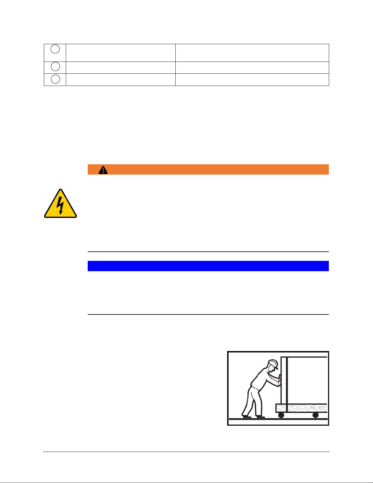
Where possible transport packed on the pallet.
Use suitable transport means (forklift or hand truck, etc.).
Page 10
CENTERLINE™ Installation and Operation Manual
10 Ver1.0 / Mar-2019 Hobart
5.4 Removing the packaging
Remove packaging materials and accessories from the machine.
Immediately after unpacking the dishwasher, check for possible shipping damage. If this machine is
found to be damaged, save packaging materials and contact the carrier within 5 days of delivery.
5.5 Installing the machine
Prior to installation, verify that the electrical supply agrees with the specifications on the machine data
label, which is located on the lower, right side of the machine.
Wall clearance is not required.
Install the provided feet in each of the bottom corners of the machine.
The machine must be level to operate properly. Place the dishwasher in its operating location.
Level the machine before any connections are made. Using a carpenter's level placed diagonally on
the rack tracks, level the machine front to back and side to side by threading the adjustable feet in
or out.
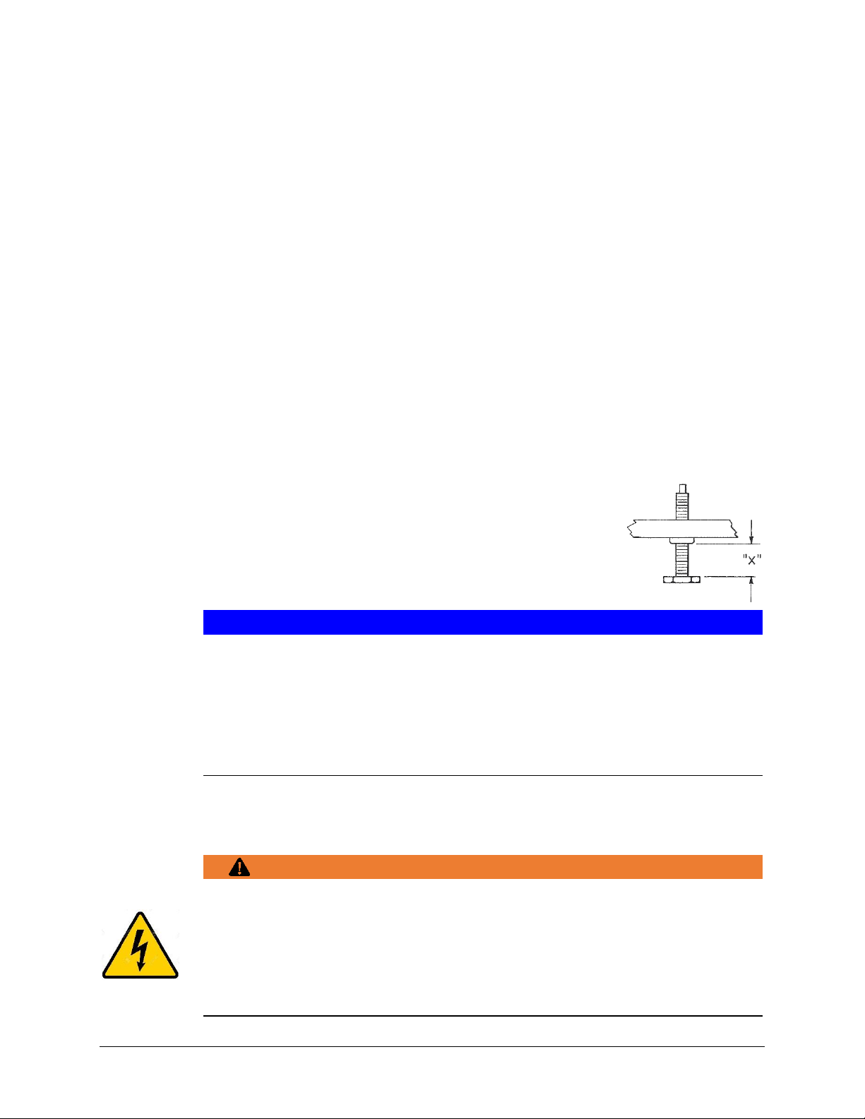
After leveling the machine, cover the exposed threads of the adjustable feet with the supplied
rubber tubing.
– Measure exposed length of threads on adjustable foot (“X”)
– Cut required length of rubber tubing, slit one side of cut piece and install
over threaded portion of adjustable foot.
NOTICE!
Property damage
NOTE: Steam generated from normal operation may escape from the door.
Wood, laminates, veneers, etc. are unsuitable materials for use in areas exposed to
dishwasher steam and detergents. Stainless steel or other moisture-resistant
shields are recommended for surfaces adjacent to machine sides and top.
5.6 Connecting to the power supply
WARNING!
Risk of electric shock
Electrical and grounding connections must comply with the applicable portions of the
National Electrical Code and/or other local electrical codes.
Disconnect the electrical power to the machine and follow lockout/tagout
procedures.
Page 11

Installation and Operation Manual CENTERLINE™
11 Ver0.4 / 18-Feb-2019 Hobart
5.6.1 Electrical Data
Complied in accordance with the National Electrical Code NFPA-70, latest addition.
NOTICE!
Supply connections
For supply connections, use copper wire only rated at 90°C minimum.
Model
Volts/Hertz/Phase
Minimum Supply Circuit
Conductor Ampacity
Maximum Protective
Device Ampacity
CUH
208/60/1
24.2
30
240/60/1
27.5
30
CUL
120/60/1
15.4
20
Refer to the data label on the lower, right side of the machine for proper selection.
5.6.2 Electrical Connection Method
Remove the lower front panel by removing the two
screws at the bottom of the panel.
Remove control board bracket and chemical
pump bracket nuts.
Page 12

CENTERLINE™ Installation and Operation Manual
12 Ver1.0 / Mar-2019 Hobart
Lower control board bracket and chemical pump bracket
to allow access to terminal block 1TB.
A hole for 1” trade size conduit is supplied at the
lower left in the back of the machine.
Install 1” trade size conduit or cable and fitting. Leave at least four feet of electrical line between
wall connection and machine. This allows machine to be pulled away from wall for cleaning and/or
servicing.
Make electrical connections according to wiring diagram supplied
with the machine and secure wires to the machine service
connection. Keep excess wire in the base of the unit to a
minimum. A cable support is supplied to facilitate wire routing.
NOTICE!
Transformer connections
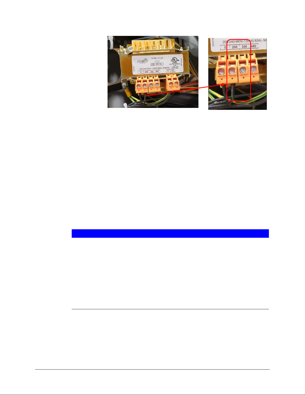
For the CUH machine a control transformer is used to step the 208V or 240V incoming
power to 120V for the control circuitry. The transformer is factory-preset to 240V.
For 208V incoming power, relocate the 1T-H wire on the transformer from the
240V terminal to the 208V terminal. (See wiring diagram supplied with machine)
1TB
Page 13
Installation and Operation Manual CENTERLINE™
13 Ver0.4 / 18-Feb-2019 Hobart
5.7 Connecting the water
NOTE: The machine must be operated with potable water.
5.7.1 Water Requirements
Proper water quality can improve ware washing performance by reducing spotting, enhancing
effectiveness of labor and extending equipment life. Water conditions vary from one location to
another. The recommended proper water treatment for effective and efficient use of this equipment
will also vary depending on the local water conditions. Ask your municipal water supplier for details
about your local water conditions prior to installation.
Recommended water hardness is 3 grains of hardness per gallon or less. Higher hardness may cause
excessive formation of lime scale. Water hardness above 3 grains per gallon requires water treatment.
Water treatment has been shown to reduce costs associated with machine cleaning, reduce deliming of
the dishwasher, and reduce detergent usage in the dishwasher.
NOTICE!
Water quality
High iron levels in the water supply can cause staining and may require an iron filter.
High chloride levels in the water supply can cause pitting and may require a chloride
removal system. Contact Hobart Service or your local water treatment professional for
proper water treatment.
Sediment may require a particulate filter. Dissolved solids may require water treatment
such as a water softener, reverse osmosis system, etc. Contact Hobart Service or your
local water treatment professional for proper water treatment.
5.7.2 Water Connection
A water hammer arrestor (meeting ASSE-1010 Standard or equivalent) should be installed (supplied by
others) in the common water supply line at the service connection.
The plumber connecting this machine is responsible for making certain that water lines are
THOROUGHLY FLUSHED OUT BEFORE connecting to the dishwasher. This "flush-out" is necessary to
Page 14
CENTERLINE™ Installation and Operation Manual
14 Ver1.0 / Mar-2019 Hobart
remove all foreign matter, such as chips (resulting from cutting or threading of pipes), pipe joint
compound from the lines; or, if soldered fittings are used, bits of solder or cuttings from the tubing.
Debris, if not removed, may lodge in the dishwasher's plumbing components and render them
inoperative. Solenoid valves fouled by foreign matter and any expenses resulting from this fouling are
NOT the responsibility of the manufacturer and associated repair costs are not covered under warranty.
A manual shutoff valve (not supplied) should be installed upstream of the fill hose to accommodate
servicing the machine. It is recommended that a line strainer (80 mesh) (not supplied) be installed in the
supply line between the manual shutoff valve (not supplied) and the connection point on the machine.
Make plumbing connections with ½” minimum copper piping OD (¾” recommended), with a ¾” male
garden hose fitting (not supplied).
Connect to hot water
Temperature:
– CUH: 110°F (43°C) minimum
– CUL: 120°F (49°C) minimum
Water hardness: max. 3 grains
Flowing pressure:
– 15 psi – 65 psi (1 bar – 4.5 bar)
– > 65 psi (4.5 bar): Provide pressure regulating valve (not supplied)
– < 15 psi (1 bar): Improper machine operation may result
NOTICE!
Pressure regulating valve
The water pressure regulator must have a relief bypass. Failure to use the proper
type of pressure regulator may result in damage to the unit.
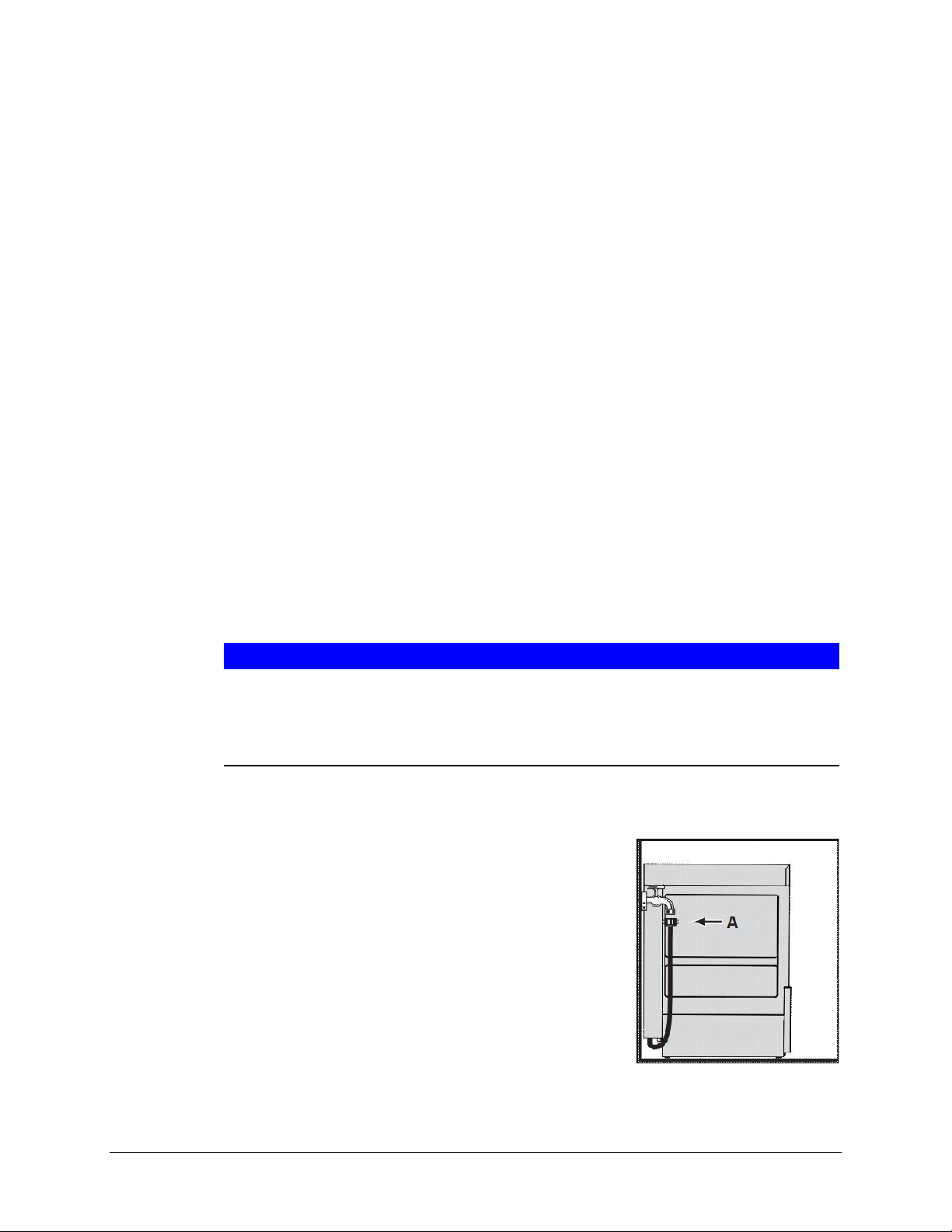
Connect the union nut “A” (¾” garden hose thread) of the water supply hose to the building shut off
valve.
Do not kink or cut the water supply hose.
Page 15

Installation and Operation Manual CENTERLINE™
15 Ver0.4 / 18-Feb-2019 Hobart
Any required extension must be made using a suitable pressure hose.
5.8 Connecting the drain
A drain hose, 19mm inside diameter, is provided.
WARNING!
Plumbing connections
Plumbing connections must comply with applicable sanitary, safety, and plumbing
codes.
The connection between machine and site drain must not exceed a maximum height of 34” above
finished floor.
Drain must have a minimum flow capacity of 5 gallons per minute.
Do not lay the drain hose loose on the ground (the hose could become frayed) but fasten it in place.
Leave at least four feet of drain hose between wall connection and machine. This allows machine to
be pulled away from wall for cleaning and/or servicing.
Do not kink drain hose.
6 SET UP
6.1 Personnel qualification
Set up must only be carried out by qualified personnel (see section 2.2.2).
6.2 Filling chemical hose (See Operator Menu for priming)
WARNING!
Chemical burns, irritation of the skin
Filling the chemical hoses with detergent, rinse aid or sanitizer for the first time
incorrectly can cause serious injury.
Wear protective equipment (gloves, safety goggles, protective clothing) when
handling chemicals.
Observe the manufacturer’s application and safety instructions.
Page 16
CENTERLINE™ Installation and Operation Manual
16 Ver1.0 / Mar-2019 Hobart
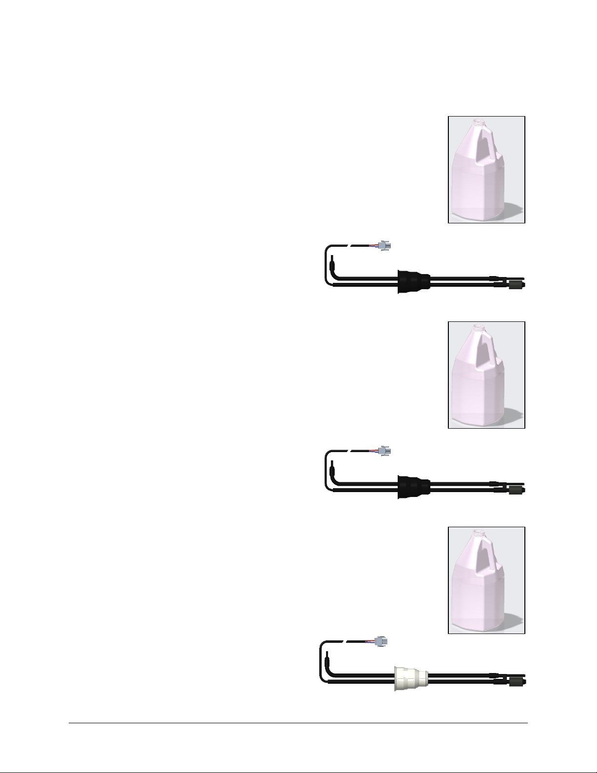
6.3 Setup of external chemical bottles
Preparing the detergent:
Suction height of detergent pump: max. 5 ft
Place clear suction tubing marked for detergent at the bottom of the external
detergent bottle/reservoir.
If machine is equipped with optional external bottle/reservoir level sensing
wand attached to the end of the detergent tubing, place that at the bottom of
the external detergent bottle/reservoir (See section 8.5.4).
Preparing the rinse aid:
Suction height of rinse aid pump: max. 5 ft
Place blue suction hose marked for rinse aid at the bottom of the external rinse
aid bottle/reservoir.
If machine is equipped with optional external bottle/reservoir level sensing
wand attached to the end of the rinse aid tubing, place that at the bottom of
the external rinse aid bottle/reservoir (See section 8.6.4).
Preparing the sanitizer (CUL machine only):
Suction height of sanitizer pump: max. 5 ft
Place the external bottle/reservoir level sensing wand that is attached to the
clear suction hose marked for sanitizer at the bottom of the external sanitizer
bottle/reservoir. (See section 8.7.4)
Page 17

Installation and Operation Manual CENTERLINE™
17 Ver0.4 / 18-Feb-2019 Hobart
7 OPERATION
7.1 Personnel qualification
The machine must be operated by qualified personnel.
7.2 Special safety instructions
WARNING!
Chemical burns, irritation of the skin, scalding
If the door is opened during operation, wash water can spray out and cause injury.
Do not open the door during operation, wait for the cycle to finish.
7.3 Notes for optimal washing result
The rinse result is significantly affected by the water quality. If the mineral content is high, the minerals
dissolved become visible on the glasses in the form of spots and streaks during the drying process.
A HOBART trained service technician can determine the water's mineral content by
measuring the grains. Recommended water hardness is 3 grains of hardness per gallon
or less. Higher hardness may cause excessive formation of lime scale. Water hardness
above 3 grains per gallon requires water treatment.
If you have any questions, please contact your authorized HOBART service partner.
7.4 Preparation for washing
7.4.1 Preparing the machine
Check correct position of pump strainer and tank strainers and proper installation of upper and
lower wash/rinse arms.
Open building water shut-off valve.
Turn on main switch, breaker, or insert the plug.
Page 18

CENTERLINE™ Installation and Operation Manual
18 Ver1.0 / Mar-2019 Hobart
Check level of detergent and rinse aid in containers (See sections 8.5.3 and 8.6.3).
For CUL machine, check level of sanitizer in container (See section 8.7.3).
Close door.
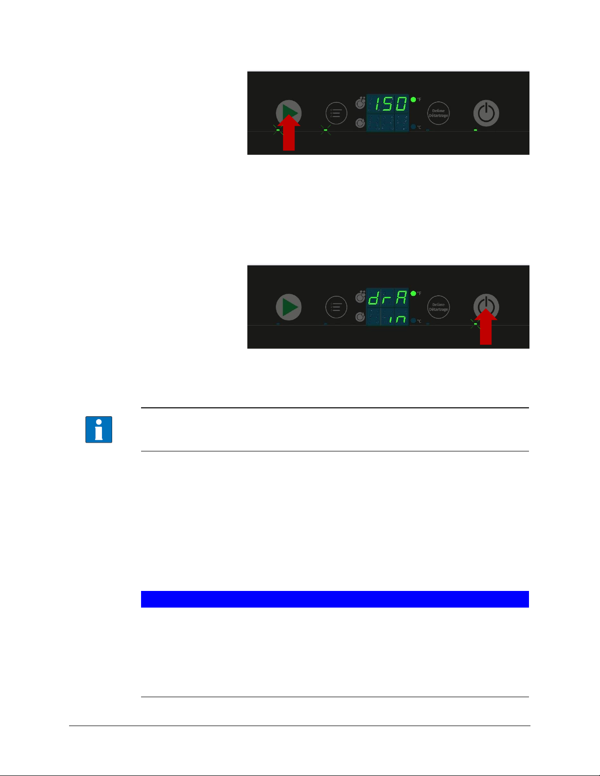
Press the Power/Drain button.
During the filling and heating processes, the Power/Drain button LED flashes. This process can
take several minutes.
As soon as the LED is permanently lit on both the Power/Drain button LED and the Start button
LED, the machine is ready for operation.
7.4.2 Preparing the ware for washing
Remove heavy food residue.
Load ware into rack.
Page 19

Installation and Operation Manual CENTERLINE™
19 Ver0.4 / 18-Feb-2019 Hobart
Rinse off ware.
7.5 Washing
Open door.
Slide rack into the machine and close the door.
Press the Start button.
While the washing cycle is running, the Start button LED flashes. As soon as the Start button
LED lights up permanently, the rinsing process is complete, and cycle ends.
The wash temperature is shown in the upper display for the entire cycle.
The rinse temperature is shown on the lower display only during the rinsing portion of the cycle.
Open the door and remove the rack.
Allow the ware enough time to dry.
7.5.1 Extending wash time
For heavier soiled ware, the wash cycle time can be extended by up to 4 minutes. (See section 8.3)
To extend the washing time, start a normal 2-minute washing cycle by pressing the Start button and
within the first 10 seconds of the cycle starting, press the Start button a 2nd time.
Page 20
CENTERLINE™ Installation and Operation Manual
20 Ver1.0 / Mar-2019 Hobart
While the extended washing cycle is running, both the Start button LED and the Menu button
LED flashes. As soon as the Start button LED lights up permanently, the rinsing process is
complete, and cycle ends.
7.6 Switch off machine
Press and hold the Power/Drain button (3 seconds).
During draining, the display will show “drA in”.
During draining, the Power/Drain button LED flashes.
During draining, the machine interior is rinsed automatically, and the tank and booster
are emptied.
At the end of the draining cycle, the machine switches off automatically.
When the machine has switched off:
Remove any heavy food residues.
Turn off main switch, breaker, or remove the plug.
Close building water shut-off valve.
7.7 Daily cleaning or after each meal period
NOTICE!
Property damage
The use of unsuitable agents can cause corrosion damage.
Do not use any bleach, acids or metal-containing additives to clean the machine.
Do not use metal brushes.
Page 21

Installation and Operation Manual CENTERLINE™
21 Ver0.4 / 18-Feb-2019 Hobart
Open the door, remove tank and pump strainers. Rinse under running water. Make sure that food
debris does not enter pump intake when the pump strainer is removed.
Clean machine interior.
Replace pump and tank strainers.
Allow time for interior to dry.
7.8 Weekly cleaning
Depress two buttons on side of lower wash/rinse arm.
Remove and clean wash/rinse arm.
Repeat for upper arm.
Replace all parts.
7.9 Removing hard water deposits (Deliming)
The dishwasher should be delimed on a regular basis as required. How often depends on the mineral
content of the water. Deliming should be done when you can see clear signs of lime deposits (a white
chalky substance) on the inside walls, on the wash and rinse arms or tank heater. Inspect the machine
Page 22

CENTERLINE™ Installation and Operation Manual
22 Ver1.0 / Mar-2019 Hobart
interior for lime deposits. When deliming is necessary, a deliming agent (such as Lime-A-Way® or LSR®)
should be used for best results.
WARNING!
Chemical mixing
Deliming solution must not come in contact with bleach or rinse solution containing
bleach. Mixing may cause hazardous gas to form. This entire procedure must be
followed step-by-step for safe and satisfactory results.
This machine is equipped with an automatic delime cycle reminder. It is recommended that deliming be
done when the Delime button LED is flashing. Deliming can also be initiated at any other time if deemed
necessary.
Machine must be on and at a ready state (Power/Drain button LED lit permanently).
Open the door, remove tank strainers. Rinse under running water.
Replace tank strainers.
Close door.
Press and hold the Delime button (minimum 3 seconds).
The upper display will show “SdL” to show that the delime cycle has started.
Page 23

Installation and Operation Manual CENTERLINE™
23 Ver0.4 / 18-Feb-2019 Hobart
The machine will enter a drain and rinse phase. During this phase the delime button LED will be
lit continuously.
The deliming cycle is extensive and can take 30 minutes or more to complete.
When ready to add deliming agent, the upper display will show “Add”. The delime button LED
will flash.
Open the door.
Add the correct amount of deliming agent to the tank according to the manufacturer’s instructions
(Refer to section 3.3 for tank volume).
WARNING!
Chemical burns, irritation of the skin.
The use of unsuitable chemicals can cause injury.
Use only commercial deliming agent.
Observe the manufacturer’s application and safety instructions.
Close the door.
The deliming process will continue. The delime button LED will be lit continuously.
The upper display will show “dL”.
When the deliming phase completes, the machine will enter a drain and rinse phase. During this
phase the delime button LED will be lit continuously.
After the deliming process is completed, the machine will drain and shut down.
Page 24

CENTERLINE™ Installation and Operation Manual
24 Ver1.0 / Mar-2019 Hobart
8 SETTINGS
8.1 Overview of operator menu
CUH (High Temp Machine)
Item
Menu Function
Function
00
Extended Wash Time
Sets extended wash time
01
Cycle Count (Rinse)
Displays number of wash/rinse cycles completed
02
Detergent Setpoint
Setting of detergent concentration (g/l)
03
Detergent Pump Prime
Primes detergent pump
04
Rinse Aid Setpoint
Setting of rinse aid concentration (g/l)
05
Rinse Aid Pump Prime
Primes rinse aid pump
08
Temperature Units
Sets temperature display to °F or °C
09
Aux Channel
Internal functions
10
Aux Channel
Internal functions
11
Aux Channel
Internal functions
CUL (Low Temp Machine)
Item
Menu Function
Function
00
Extended Wash Time
Sets extended wash time
01
Cycle Count (Rinse)
Displays number of wash/rinse cycles completed
02
Detergent Setpoint
Setting of detergent concentration (g/l)
03
Detergent Pump Prime
Primes detergent pump
04
Rinse Aid Setpoint
Setting of rinse aid concentration (g/l)
05
Rinse Aid Pump Prime
Primes rinse aid pump
06
Sanitizer Setpoint
Setting of sanitizer concentration (ppm)
07
Sanitizer Pump Prime
Primes sanitizer pump
08
Temperature Units
Sets temperature display to °F or °C
09
Aux Channel
Internal functions
10
Aux Channel
Internal functions
11
Aux Channel
Internal functions
Page 25
Installation and Operation Manual CENTERLINE™
25 Ver0.4 / 18-Feb-2019 Hobart
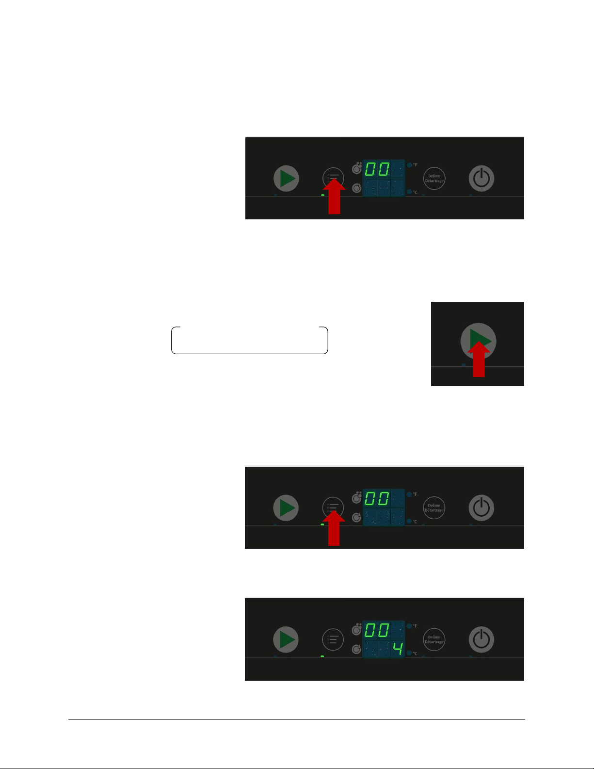
8.2 Opening the operator menu
Note: Machine must be in ready (idle) state.
Press the Menu button to access operator program settings.
The menu opens, and the Menu button LED illuminates.
The upper display will show the first item “00”.
To scroll from one item to the next, press the Wash button. After the last item, the sequence will
return to the first item.
To save and exit the operator menu at any time, open the machine door and then close it.
8.3 Extended wash time
Top display shows “00”
Press the Menu button to edit settings
Bottom display shows current extended wash setting (in minutes): (default = 4)
→ 00 → 01 → 02 → … → 11 →
Page 26
CENTERLINE™ Installation and Operation Manual
26 Ver1.0 / Mar-2019 Hobart
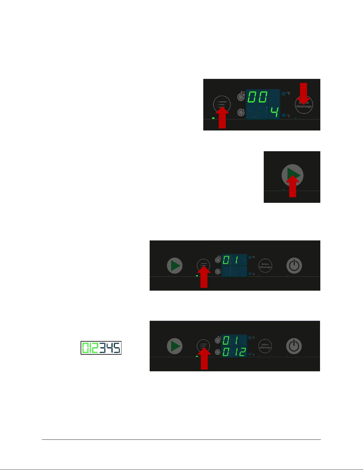
Extended Wash setting can be set from 3 minutes to 6 minutes total wash time in 1-minute intervals.
To increase time, press the Menu button
To decrease time, press the Delime button
To save and exit the edit mode, either:
Press Start Button to move to next item
– Or –
Open and close door (Will also exit operator menu)
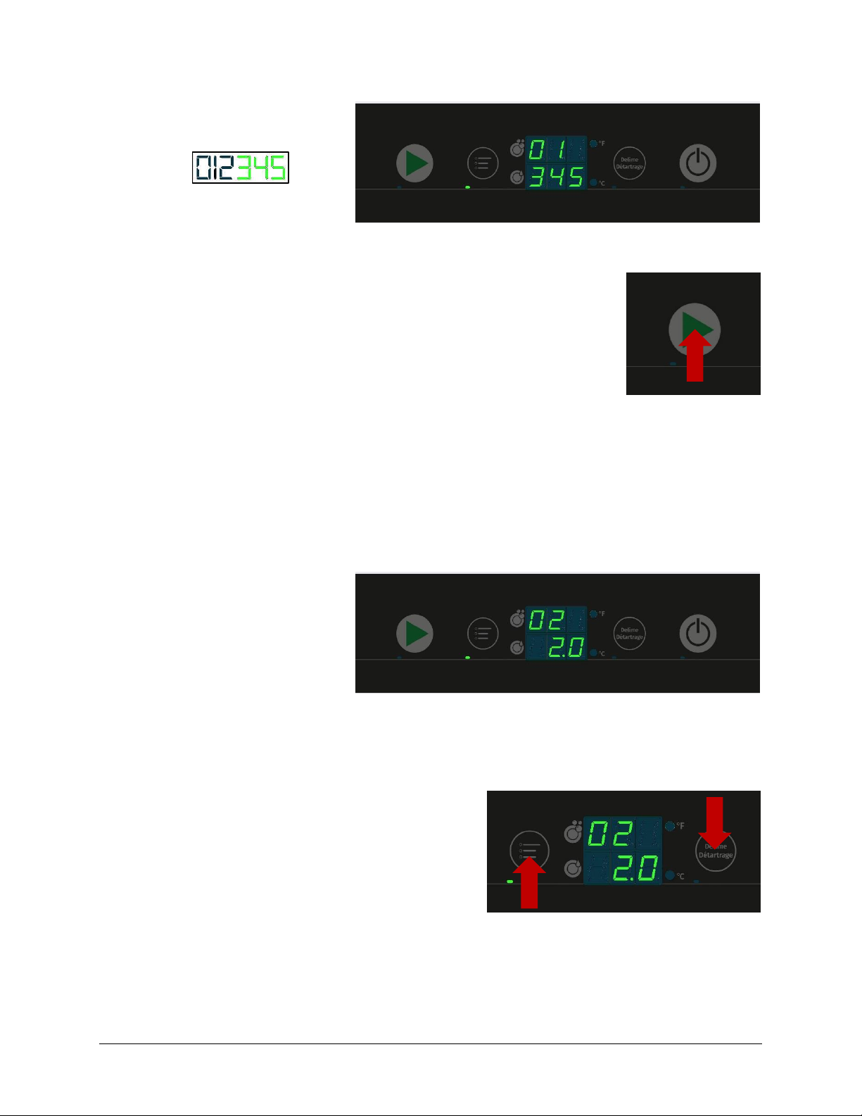
8.4 Cycle count
Top display shows “01”
Press the Menu button to display the cycle count
Bottom display shows first 3 digits of the 6-digit cycle count number (ex. 012345)
Press the Menu button a 2
nd
time
Bottom display shows last 3 digits of the 6-digit cycle count number (ex. 012345)
Page 27
Installation and Operation Manual CENTERLINE™
27 Ver0.4 / 18-Feb-2019 Hobart
To exit the cycle count menu, either:
Press Start Button to move to next item
– Or –
Open and close door (Will also exit operator menu)
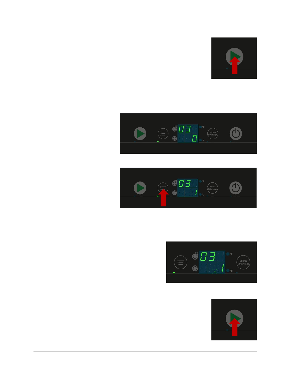
8.5 Detergent dispensing
8.5.1 Setting detergent dispensing amount
Top display shows “02”
Bottom display shows current detergent dispensing settings in g/L: (default = 2.0 g/L)
Note: 1.0 g/L ≈ 0.1 % concentration (by vol.)
Detergent dispensing amount can be set from 0.0 g/L to 9.5 g/L in 0.5 g/L increments.
To increase dosage by 0.5 g/L, press the Menu button
To decrease dosage by 0.5 g/L, press the Delime button
To save and exit, either:
Page 28
CENTERLINE™ Installation and Operation Manual
28 Ver1.0 / Mar-2019 Hobart
Press Start Button to move to next item
– Or –
Open and close door (Will also exit operator menu)
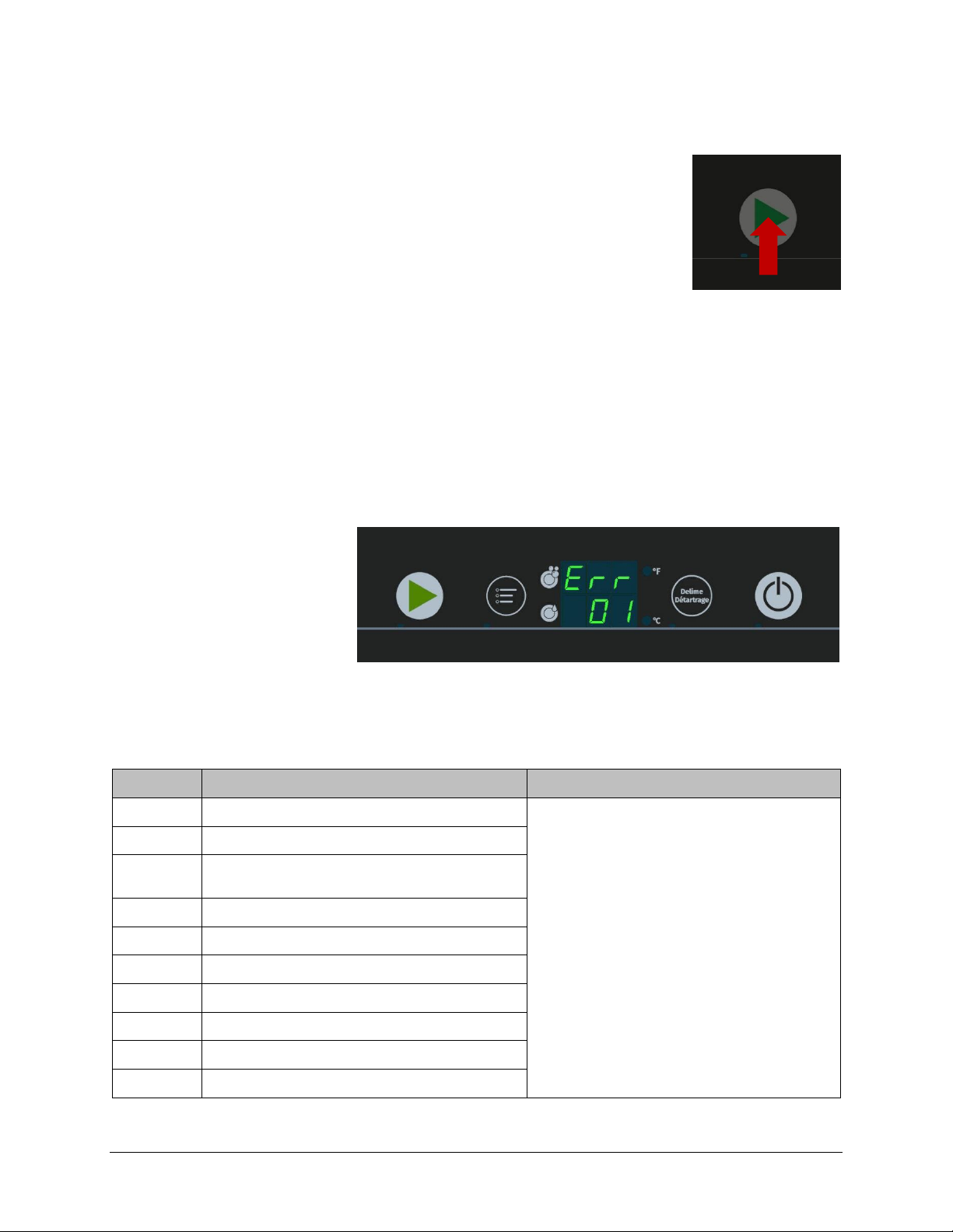
8.5.2 Priming detergent dispensing pump
Top display shows “03”
Bottom display shows “0”
Press the Menu button to change bottom display value to “1”
Press delime button to begin detergent dispensing pump priming
The detergent dispensing pump will activate for 60 seconds
The decimal point in the bottom display will flash while the dispensing pump is on
To exit the priming menu, either:
Press Start Button to move to next item
– Or –
Open and close door (Will also exit operator menu and stop priming)
Page 29

Installation and Operation Manual CENTERLINE™
29 Ver0.4 / 18-Feb-2019 Hobart
8.5.3 Inspecting detergent supply
Inspect detergent bottle for chemical present and that the supply tube is correctly inserted.
If air bubbles present in detergent line – prime (refer to 8.5.2)
8.5.4 Detergent supply level sensor (Optional)
Inspect detergent bottle for chemical present.
Make sure bottle level sensor is correctly inserted into bottle with
float sensor at bottom of bottle.
8.6 Rinse aid dispensing
8.6.1 Setting rinse aid dispensing amount
Top display shows “04”
Bottom display shows current rinse aid dispensing settings in g/L: (default = 0.6 g/L)
Note: 0.1 g/L ≈ 0.33 mL/cycle
Rinse aid dispensing amount can be set from 0.0 g/L to 2.0 g/L in 0.1 g/L increments.
To increase dosage by 0.1 g/L, press the Menu button
To decrease dosage by 0.1 g/L, press the Delime button
To save and exit, either:
Press Start Button to move to next item
– Or –
Open and close door (Will also exit operator menu)
Page 30

CENTERLINE™ Installation and Operation Manual
30 Ver1.0 / Mar-2019 Hobart
8.6.2 Priming rinse aid dispensing pump
Top display shows “05”
Bottom display shows “0”
Press the Menu button to change bottom display value to “1”
Press delime button to begin rinse aid dispensing pump priming
The rinse aid dispensing pump will activate for 120 seconds
The decimal point in the bottom display will flash while the dispensing pump is on
To exit the priming menu, either:
Press Start Button to move to next item
– Or –
Open and close door (Will also exit operator menu and stop priming)
8.6.3 Inspecting rinse aid supply
Inspect rinse aid bottle for chemical present and that the supply tube is correctly inserted.
If air bubbles present in rinse aid line – prime (refer to 8.6.2)
Page 31

Installation and Operation Manual CENTERLINE™
31 Ver0.4 / 18-Feb-2019 Hobart
8.6.4 Rinse aid supply level sensor (Optional)
Inspect rinse aid bottle for chemical present.
Make sure bottle level sensor is correctly inserted into bottle with
float sensor at bottom of bottle.
8.7 Sanitizer dispensing (CUL machine only)
8.7.1 Setting sanitizer dispensing amount
– Under Development –
8.7.2 Priming sanitizer dispensing pump
WARNING!
Chemical mixing
Deliming solution must not come in contact with bleach. Mixing may cause hazardous
gas to form. Do not prime sanitizer pump while in the delime process.
Top display shows “07”
Bottom display shows “0”
Press the Menu button to change bottom display value to “1”
Press delime button to begin sanitizer dispensing pump priming
The sanitizer dispensing pump will activate for 130 seconds
The decimal point in the bottom display will flash while the dispensing pump is on
Page 32

CENTERLINE™ Installation and Operation Manual
32 Ver1.0 / Mar-2019 Hobart
To exit the priming menu, either:
Press Start Button to move to next item
– Or –
Open and close door (Will also exit operator menu and stop priming)
8.7.3 Inspecting sanitizer supply
Inspect sanitizer bottle for chemical present and that the supply level sensor is correctly inserted.
If air bubbles present in sanitizer line – prime (refer to 8.7.2)
8.7.4 Sanitizer supply level sensor
Make sure bottle level sensor is correctly inserted into bottle with
float sensor at bottom of bottle.
8.8 Temperature display units
Top display shows “08”
Bottom display shows current temperature units: (Default is “F”)
Press the Menu button or the Delime button to change bottom display to “F” (°F) or “C” (°C)
Page 33
Installation and Operation Manual CENTERLINE™
33 Ver0.4 / 18-Feb-2019 Hobart
To exit the temperature units display menu, either:
Press Start Button to move to next item
– Or –
Open and close door (Will also exit operator menu)
8.9 Aux Channels
– Reserved for Internal Functions –
9 DISPLAY OF ERRORS AND INFORMATION
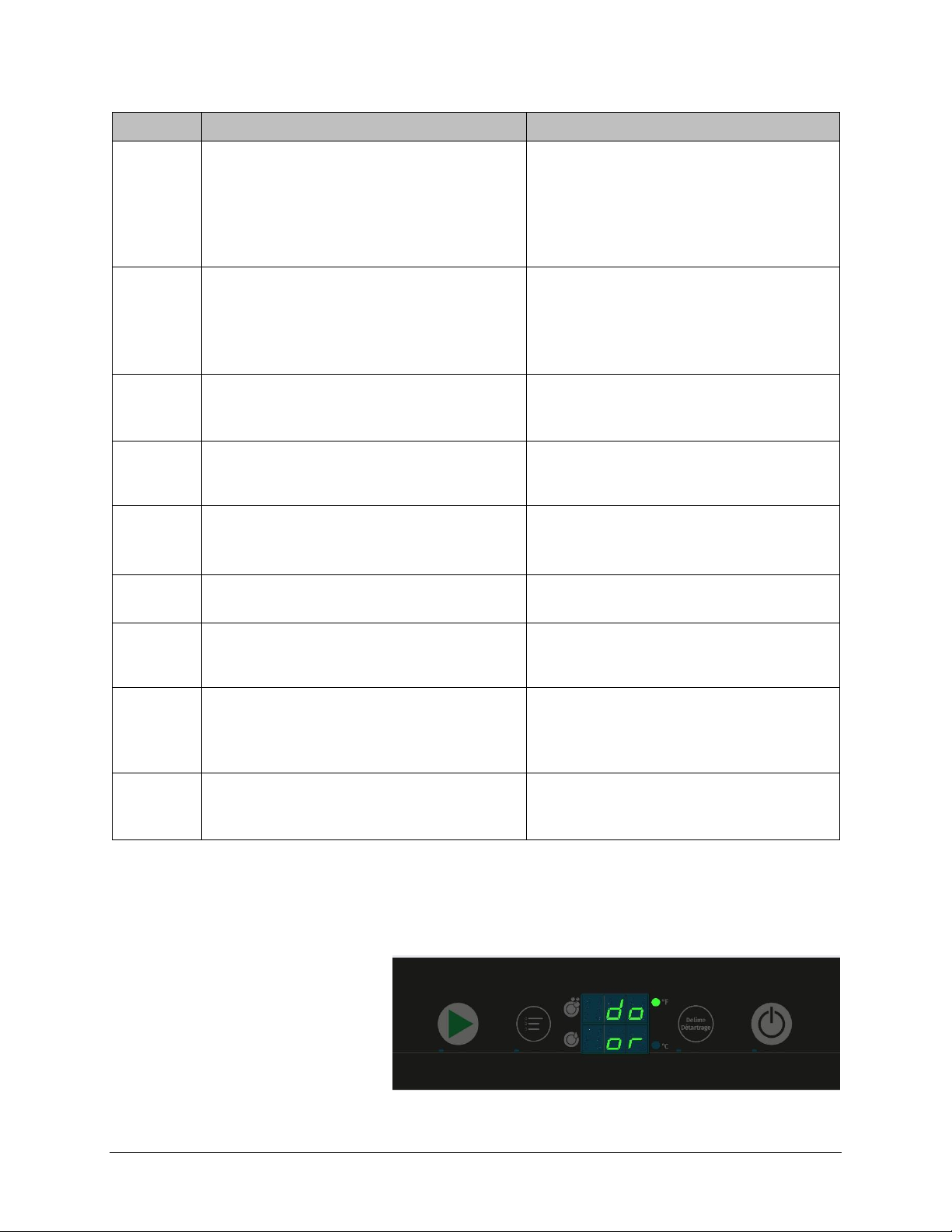
9.1 Error
“Err” appears in the top display.
The error code is shown in the bottom display (see table).
Error code
Symptom
Possible Solution*
01
Exceeded booster sensor temperature
1. Drain tank and refill.
2. Unplug the machine from wall. If unit is
hardwired, turn circuit breaker off then
back on.
3. If error code persists, contact qualified
Hobart Service.
02
Low booster sensor temperature
03
Booster overtemperature protector while washing
exceeded
04
Booster heater not enabling
05
Exceeded tank sensor temperature
06
Low tank sensor temperature
07
Booster pressure sensor exceeded upper limit
08
Booster pressure sensor exceeded lower limit
09
Tank pressure sensor exceeded upper limit
10
Tank pressure sensor exceeded lower limit
Page 34
CENTERLINE™ Installation and Operation Manual
34 Ver1.0 / Mar-2019 Hobart
Error code
Symptom
Possible Solution*
12
Wash tank water level error
1. Verify drain hose is not pinched during
drain cycle operation.
2. Drain tank and refill.
3. Unplug the machine from wall. If unit is
hardwired, turn circuit breaker off then
back on.
13
Wash tank pressure error
1. Check water level.
2. Drain tank and refill.
3. Unplug the machine from wall. If unit is
hardwired, turn circuit breaker off then
back on.
14
Wash tank drain error
1. Verify drain hose is not pinched
2. Check drain hose for any debris and drain
again.
18
Booster fill error
1. Check water line for flow and/or verify line
is not pinched. Error will go away with
water flow.
19
Detergent, rinse aid or sanitizer deficiency
1. Low or no chemicals.
2. Float level below working condition.
3. Missing jumpers for chemical level sensor.
22
Low rinse temperature
Rinse temp below 180°F.
Error will clear if rinse temp over 180°F.
28
Water level too low when wash program starts
1. Top off water level in wash tank then start
wash cycle. Error will clear if water level is
reached
30
Booster overtemp exceeded while filling
1. Drain tank and refill
2. Unplug the machine from wall. If unit is
hardwired, turn circuit breaker off then
back on
31
Fill valve error
1. Check water line for flow and/or verify line
is not pinched.
1. Drain tank and refill
*If error code persists, contact Hobart Service 1-888-4HOBART
9.2 Information
The following notes are displayed with a combination of letters in the display in the display.
Page 35
Installation and Operation Manual CENTERLINE™
35 Ver0.4 / 18-Feb-2019 Hobart
Display
Reason
Remedy
do
or
Filling, washing draining or delime program
interrupted
Close door
10 TROUBLESHOOTING GUIDE
10.1 Poor wash results
Fault Type
Possible Cause
Remedy
Ware not
clean
Wash arm hard to turn (must rotate easily by
hand).
• Remove wash arms and clean them
thoroughly.
• Also check that water manifold from
machine to wash arm is clear.
Wash arm nozzles are clogged (visual check).
• Remove wash arm and rinse wash arm
thoroughly until all soiling is removed.
Rinse nozzles clogged (usually by lime
deposit).
• Remove rinse arms and delime them
in separate container.
• Check building softening system for
function.
• Delime machine if needed.
Detergent concentration is too low or too
high.
Check detergent concentration setting (See
operating instructions.
Tank strainers clogged.
Remove right, left and center strainer pans,
empty and clean strainers.
Pump strainer clogged.
Remove, empty and clean strainer.
Wrong program selected for heavily soiled wash
ware.
Extend the wash program for longer wash cycle.
Ware or
glasses dry
poorly
Rinse aid concentration too low.
Increase concentration (see operating
instructions).
Wash ware still greasy.
Detergent concentration too low: increase
(see operation instructions).
Check if detergent is appropriate. If not,
choose a stronger one.
Drain contaminated water and refill
machine. Ensure better pre-scrapping of the
wash ware.
Wash ware remains in the machine too long at
the end of wash cycle.
Remove wash ware as soon as cycle is
completed to enable it to dry.
Streaks and
spots on
ware or
glasses
Rinse aid concentration too high (stripe or
bubble formation).
Reduce concentration (see operating
instructions).
Hard water or high mineral content.
Check water quality.
Improper rinse aid
Consult your local chemical provider
Inadequate rinse aid dispensing causes stains.
Increase rinse aid concentration (see operating
instructions).
Page 36

CENTERLINE™ Installation and Operation Manual
36 Ver1.0 / Mar-2019 Hobart
10.2 Other faults
Fault Type
Possible Causes
Remedy
Glasses are totally or
partially cloudy.
Surface of glasses is rough and
porous, this is called glass etching.
Use new glasses, this is not caused by a
malfunction on the machine.
Glass/dish breakage.
Use of unsuitable dish or glass racks.
Use suitable racks.
11 MAINTENANCE
Genuine spare parts must be used for repairs and maintenance part replacements. Maintenance parts
include chemical dispensing tubes, rinse arm bearings, etc.
Contact your Hobart Service office for any repairs or adjustments needed on this equipment. Long-term
service contracts are available on this and other Hobart products.
12 DISPOSAL
The machine operator is responsible for disposing of the machine and its operating materials correctly
and in accordance with environmental regulations. Observe the national and local regulations.
13 PRODUCT DISCLAIMER
Installations and repairs carried out by non-authorized technicians or using non-genuine spare parts,
and any technical alterations to the machine not approved by the manufacturer will invalidate the
manufacturer's warranty.
HOBART reserves the right to make changes or improvements to its products without prior notice.
 Loading...