

Page 1
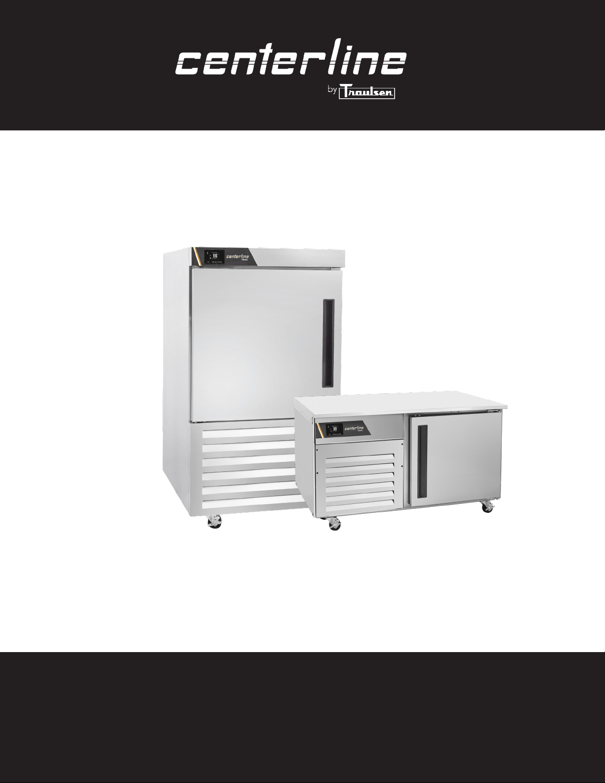
OWNER’S MANUAL
Instructions for the installation, operation and maintenance
of all Centerline™ by Traulsen Blast Chiller* models:
CLBC4 (4 pan level undercounter model)
CLBC7 (7 pan level reach-in model)
*Please Note: Traulsen’s blast chillers are solely intended for blast chilling and not for use as holding cabinets.
4401 Blue Mound Road Fort Worth, Texas 76106 (USA)
Phone: 800.825.8220 | Service Fax: 817.740.6757 | E-mail: [email protected] | Website: centerlinefoodequipment.com
Hours of Operation: Monday - Friday 7:30 a.m. - 4:30 p.m.
(CST)
Page 2
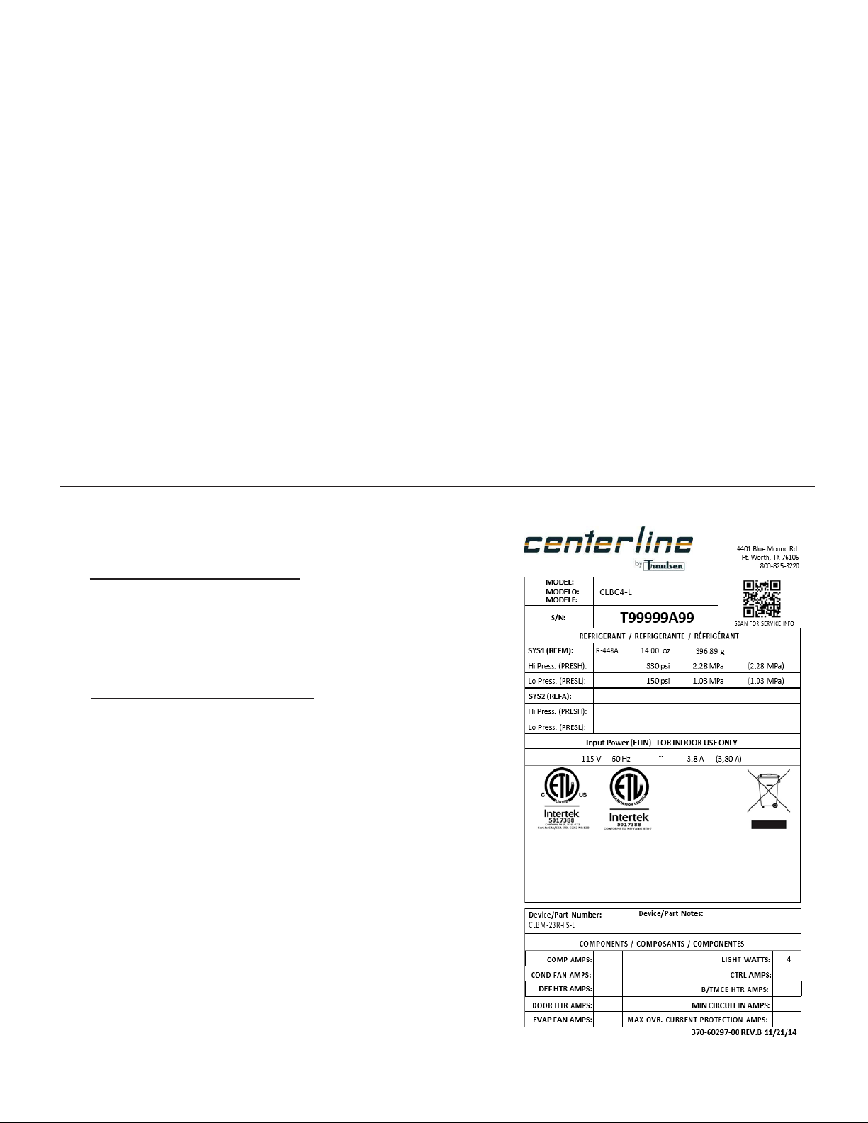
TABLE OF CONTENTS
I. THE SERIAL TAG Page 1
a) Serial Tag & Location Page 1
b) Reading The Serial Tag Page 1
II. RECEIPT INSPECTION Page 2
III. INSTALLATION Page 2
a) Location Page 2
b) Packaging Page 2
c) Installing Casters or Legs Page 2
d) Installing Condensate Pan Page 3
e) Installing Shelves Page 3
f) Cord & Plug Page 3
g) Power Supply Page 3
h) Wiring Diagram Page 4
IV. Basic Operating Guidelines Page 4
a) Chilling within HACCP Guidelines Page 4
b) Loading Page 4
c) Use of Food Probe Page 4
d) Covering Product Page 4
V. CARE AND MAINTENANCE Page 5
a) Cleaning the Condenser Page 5
b) Replacing the Gaskets Page 5
c) Cleaning the Exterior Page 5
d) Cleaning the Interior Page 5
VI. CONTROL BASICS Page 6
a) Introduction Page 6
b) Basic Operations Page 6
c) Other Functionalities Page 7
d) Wiring Diagrams Page 8
VII. TROUBLESHOOTING GUIDE Page 9
VIII. SERVICE/WARRANTY INFORMATION Page 10
a) Service Information Page 10
b) Spare Parts Information Page 10
c) Warranty Registration Page 10
d) Warranty Statement Page 11
I. THE SERIAL TAG
I. a - SERIAL TAG & LOCATION
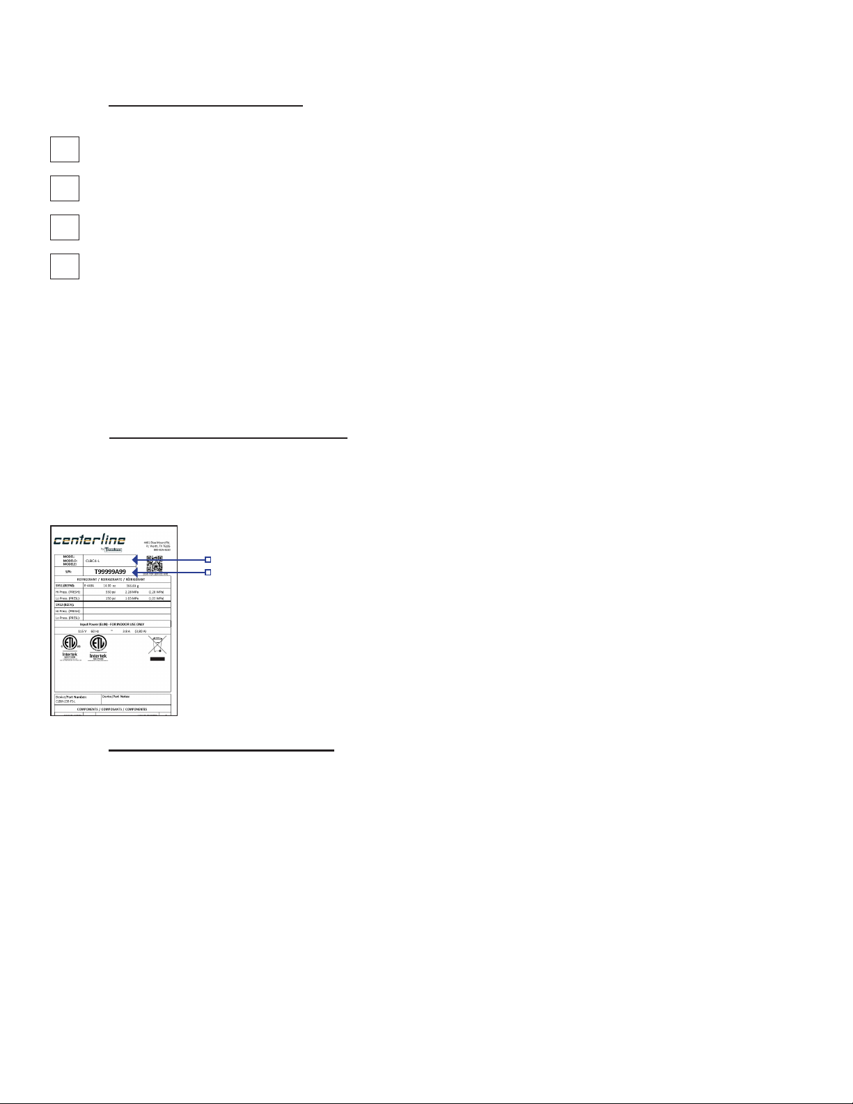
The serial tag is a permanently afxed label on which is recorded
vital electrical and refrigeration data about your Centerline product,
as well as the model and serial number. This tag is located in
upper right interior of blast chiller models.
I. b - READING THE SERIAL TAG
• Model = The model number of your Centerline unit
• (S/N) Serial Number = The permanent ID number of your
Centerline unit
• Refrigerant SYS1 = System 1 Refrigerant type used and
refrigerant charge
• Design Pressure = System 1 High and Low Pressure
• Refrigerant SYS2 = System 2 Refrigerant type used and
refrigerant charge
• Design Pressure = System 2 High and Low Pressure
• Volts = Voltage
• Hz = Cycle
• PH = Phase
• Total Current = Maximum amp draw
• Min Circuit Amps = Minimum circuit ampacity
• Lights = Light wattage
• Agency Labels = Designates agency listings
• Components = Component Ratings
-1-
Page 3
II. RECEIPT INSPECTION III. INSTALLATION (continued)
II. a - RECEIPT INSPECTION
All Centerline products are factory tested for performance
and are free from defects when shipped. The utmost care
has been taken in crating this product to protect against
damage in transit. All interior ttings have been carefully
secured and the casters/legs are boxed and strapped inside
to prevent damage.
You should carefully inspect your Centerline unit for damage
upon delivery. If damage is detected, you should save all
the crating materials and make note on the carrier’s Bill of
Lading describing the damage. A freight claim should be
led immediately. If damage is subsequently noted during or
immediately after installation, contact the respective carrier
and le a freight claim. Under no condition may a damaged
unit be returned to Traulsen without rst obtaining written
permission (return authorization). You may contact Traulsen
customer care at (800) 333-7447 and select option 2 to
request a return.
III. INSTALLATION
III. c - INSTALLING CASTERS OR LEGS
A set of four (4) 4” high casters are supplied standard for
all Centerline blast chiller units. These are shipped from the
factory packed inside a cardboard box which is strapped
inside the cabinet.
Legs & 6” casters are available in lieu of 4” casters as an
optional accessory kit for the same models. These are
shipped inside a separate cardboard box containing four
(4) casters or legs.
THE CABINET MUST BE BLOCKED AND
STABLE BEFORE INSTALLING LEGS OR CASTERS.
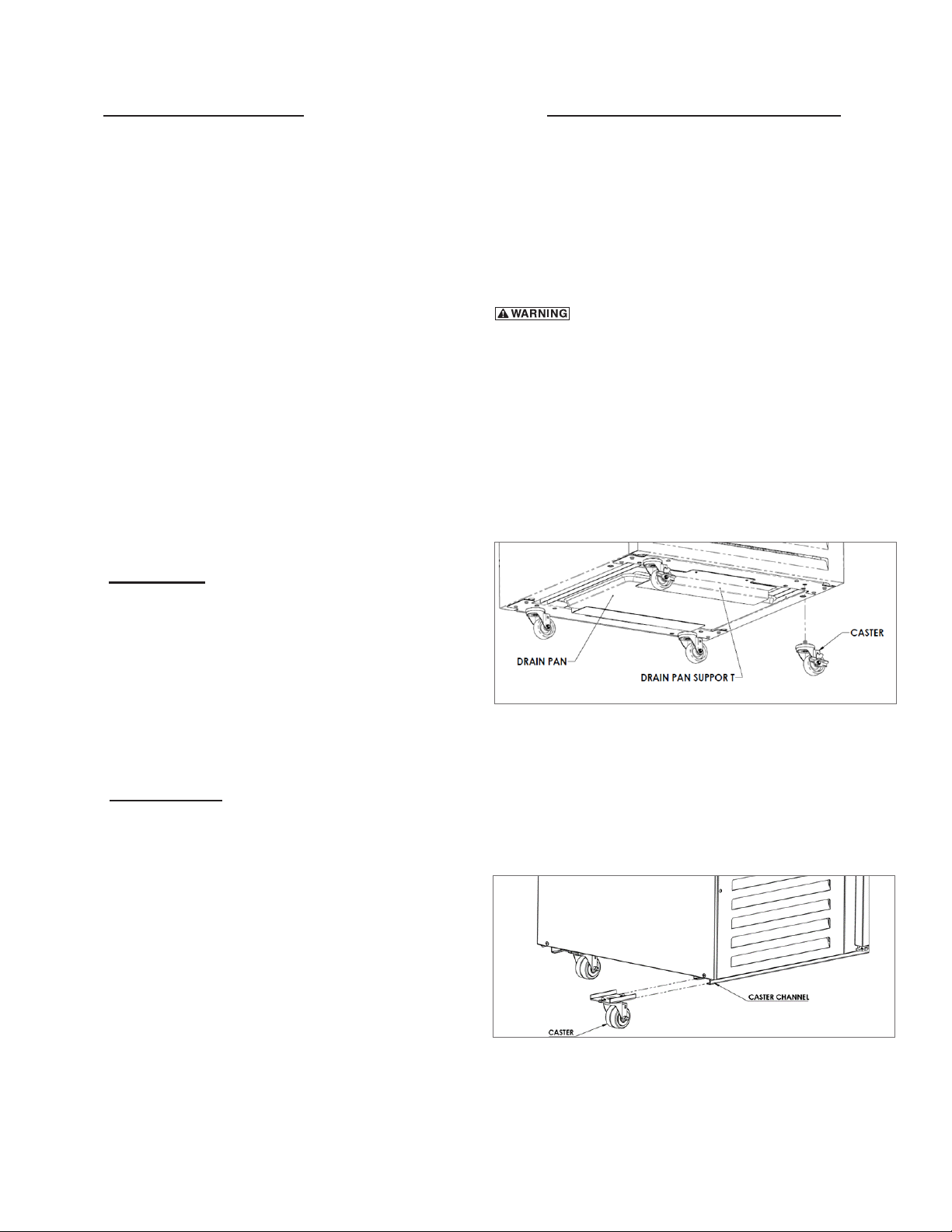
To install the legs or casters, rst raise and block the unit a
minimum of 7” from the oor.
For the reach-in model, stem casters are installed by
threading them rmly into the cabinet bottom at each corner
(see Figure 1). For leveling, turn the casters counterclockwise
to raise it, or clockwise to lower it. Level the unit from front
to back as well as side to side in this manner. The caster
bolts are tightened using a 1/2” socket wrench.
III. a - LOCATION
Select a proper location for your Centerline unit, away from
extreme heat and allow proper clearance for air circulation.
Make certain that there are no obstructions in front of the
louver panel. Allow enough clearance between the unit and
the side wall in order to make use of the door stay open
feature at 110° (self-closing feature operates up to 90°). The
door(s) must be able to open a minimum of 90° in order to
make use of the maximum clear door width available.
III. b - PACKAGING
All Centerline units are shipped from the factory bolted to a
sturdy wooden pallet and durably packaged. Care should
be taken when removing the packaging to avoid scratching
the unit’s exterior metal nish.
Most exterior stainless steel surfaces have a protective
vinyl covering to prevent scratching during manufacturing,
shipping and installation. After the unit is installed in place of
service, remove and discard the covering from all surfaces
If possible, we suggest that the cabinet remain bolted to the
pallet during all transportation to the point of nal installation.
To remove the wooden pallet, the bolts can then be removed
with a 3/4” socket wrench. Avoid laying the unit on its front,
side or back for removal of the pallet.
NOTE: DO NOT LAY THE UNIT ON ITS SIDE DURING
TRANSPORTATION OR INSTALLATION.
Fig. 1
For the undercounter model, slide the casters or legs into
the two channels under the front and back of the cabinet
(see Figure 2). Secure in place by tightening the two bolts
located at the base of each caster or leg.
NOTE: Casters or legs must be installed towards the
four corners of the unit for proper support.
Fig. 2
Please note that Centerline units are not designed to be
moved while on legs. If the unit requires moving, a pallet
jack or fork- lift should be used to prevent damage. Make
sure the forks are clear of the condensate pan brackets.
-2-
Page 4
III. INSTALLATION (continued)
III. d - INSTALLING CONDENSATE PAN
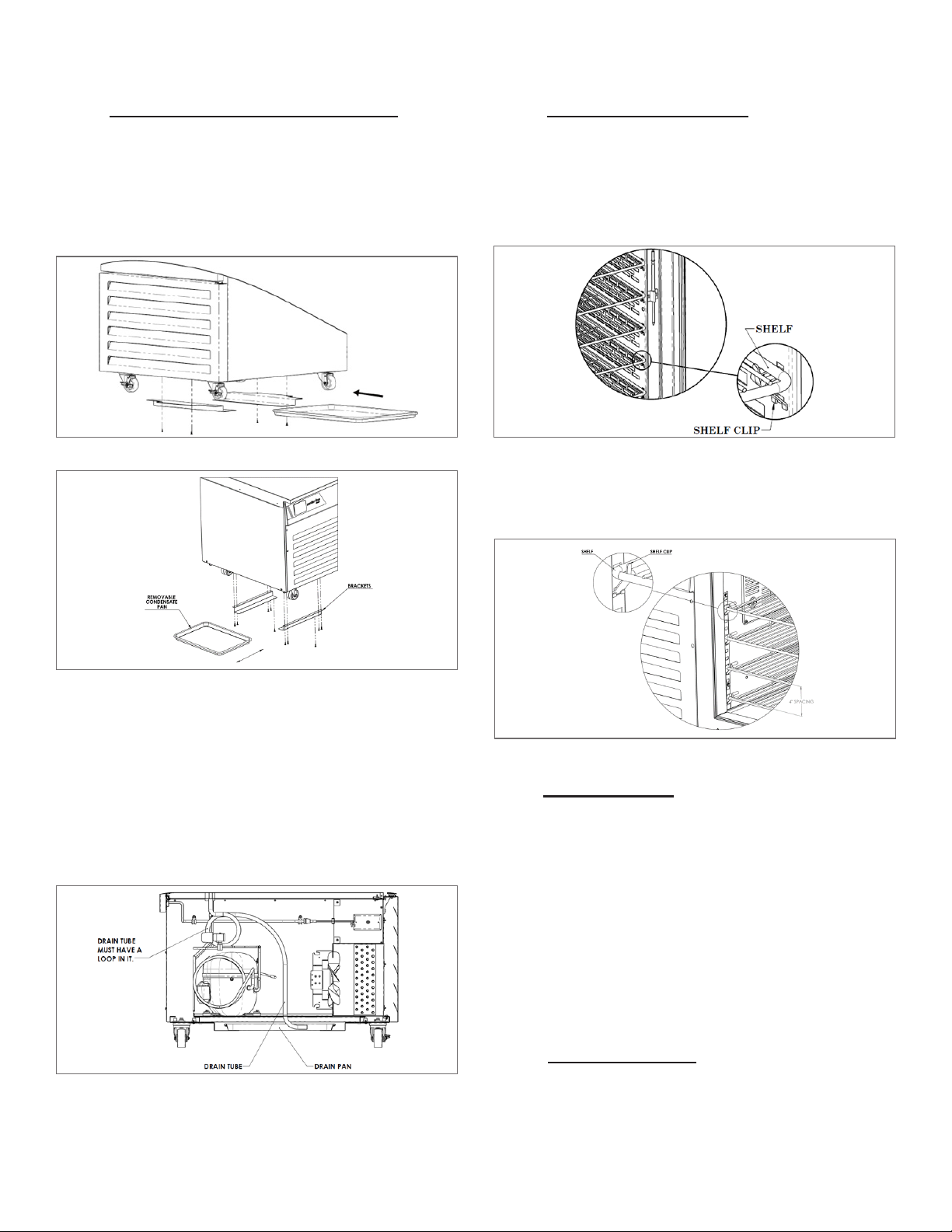
Centerline blast chillers are shipped with the condensate
pan wrapped up and stored inside the unit.
Remove the full/half-size sheet pan (condensate pan) and
slide it on the rails underneath the cabinet (see Figures 3 &
4).
Fig. 3
III. e - INSTALLING SHELVES
All Centerline blast chiller units are supplied with shelves
and shelf clips.
For the reach-in model, install the clips in the square cutouts
located on the side air ducts. Slide the shelf on the clips (see
Figure 6).
Fig. 6
For the undercounter model, install clips into pilasters located
on the sides and back of the interior. Shelves must be spaced
4” apart for optimal performance (see Figure 7).
Fig. 4
Note: DO NOT cut the wire tie for the “P” loop on the
drain tube.
For the reach-in model, route the drain tubing into the
condensate pan.
For the undercounter model, route the drain tubing through
the hole in the compressor plate and into the condensate
pan (see Figure 5).
Fig. 5
-3-
Fig. 7
III. f - CORD & PLUG
All Centerline blast chiller models are supplied with a cord
& plug attached. It is shipped coiled and secured by a nylon
strip to the back of the cabinet near condensing unit area.
For your safety and protection, all units supplied with a cord
and plug include a special three-prong grounding plug on
the service cord. Select only a dedicated electrical outlet
with grounding plug for power source.
NOTE: DO NOT UNDER ANY CIRCUMSTANCES CUT
OR REMOVE THE ROUND GROUNDING PRONG
FROM THE PLUG OR USE AN EXTENSION CORD.
III. g - POWER SUPPLY
The supply voltage should be checked prior to connection
to be certain that proper voltage for the cabinet wiring
is available (refer to the serial tag to determine correct
unit voltage). Make connections in accordance with local
electrical codes. Use qualied electricians.
Page 5
III. INSTALLATION (continued) IV. BASIC OPERATING GUIDELINES
III. g - POWER SUPPLY (cont’d)
Use of a separate, dedicated circuit is required. Size wiring
to handle indicated load and provide necessary over current
protector in circuit (see amperage requirements on the unit’s
serial tag).
III. h - WIRING DIAGRAM
Refer to the wiring diagram located on the exterior back
of the cabinet for any service work performed on the unit.
Should you require one, please contact Traulsen Service at
(800) 825-8220, and provide the model and serial number
of the unit involved.
IV. BASIC OPERATING GUIDELINES
IV. a - CHILLING WITHIN HACCP GUIDELINES
The current FDA Food Code allows much more time for safe
chilling than 90-minutes. This actually requires two critical
control points of:
a) From 135° to 70°F within two hours, then...
b) From 70° to below 41°F within additional four hours,
for a total chill time from 135° to below 41°F of no
more than six hours.
Total chill time can exceed six-hours in duration and still be
safe. This safety threshold does not include:
a) Any time needed for product to chill from any start
temp down to 135°F, or...
b) Any time elapsed to chill to below 41°F.
IV. b - LOADING
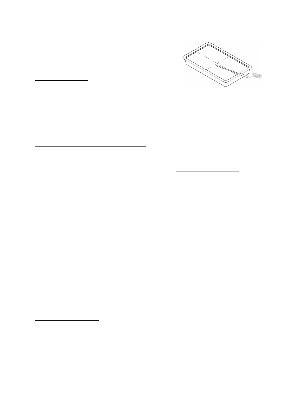
To achieve quickest chill times product should be loaded to
a depth of no greater than 2” (see Figure 8).
Products should always be loaded into the shallowest pan
possible.
Chilling of products of greater than 2” depth is often possible
within FDA guidelines. However please note that actual chill
times are a function of: Start Temperature, Product Density,
Product Depth, and Total Load.
IV. c - USE OF FOOD PROBE
For most accurate results, the food probe should be used. It
needs to be properly placed in the center of the thickest part
of the product to ensure an accurate temperature reading
(see Figure 8).
IV. c - USE OF FOOD PROBES (cont’d)
Fig. 8
Products that are not suitable for use of the food probe
should:
a. Be chilled by TIME.
b. The correct chill time should be established by the
operator based upon actual product testing.
c. The end cycle temperature should be veried
manually with a clean, accurate thermometer as soon
as the pre-established chill time elapses.
IV. d - COVERING PRODUCT
Product does not always need to be covered. However,
before doing so, please consider the following potential
scenarios:
a) If large loads of especially hot product are chilled,
there is the potential to freeze the coil.
b) Loads of uncovered product that require especially
long chilling times may have the potential to
experience surface drying.
c) Loads that are left uncovered in the chiller for long
periods after completion of a chill cycle may also
experience surface drying of the product if left
uncovered.
d) Loads of especially liquid product, such as soup,
are highly recommended to be covered in order to
prevent accidental spillage.
e) Some foods, such as rice and pasta, are particularly
vulnerable to drying and so should always be
covered.
-4-
Page 6
V. CARE AND MAINTENANCE
V. a - CLEANING THE CONDENSER
DISCONNECT ELECTRICAL POWER SUPPLY
BEFORE CLEANING ANY PARTS OF THE UNIT.
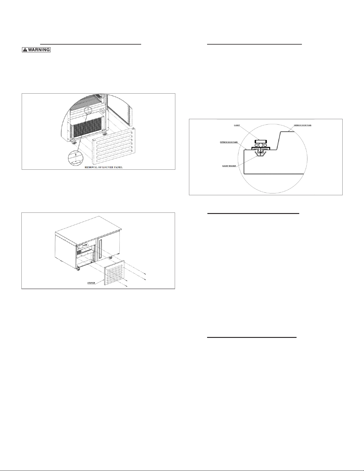
For reach-in models, remove the front lower louver panel by
removing the single screw from inside the door opening and
gently pulling it towards the front (see Figure 9).
Fig. 9
For undercounter models, remove the four (4) screws
securing the front louver panel and remove the panel (see
Figure 10).
Fig. 10
NOTE: DOOR SWITCH WIRING MAY BE PRESENT AND
ATTACHED TO THE LOUVER.
Vacuum or brush any dirt, lint or dust from the finned
condenser coil, the compressor and other cooling system
parts. If signicant dirt is clogging the condenser ns, use
compressed air to blow this clear. Care should be taken
not to bend any of the condenser ns, as this will reduce
performance and compressor life. Reverse the process to
install louver assembly back in place.
V. c - REPLACING THE GASKETS
To replace the gasket, grasp it rmly by one corner and pull
it out. Before attempting to install a new gasket, both the
unit and gasket must be at room temperature. Insert the four
corners rst by using a rubber mallet (or hammer with a block
of wood). After the corners are properly inserted, work your
way towards the center from both ends by gently hitting with
a mallet until the gasket is completely seated in place (see
Figure 11 for proper gasket placement).
Fig. 11
V. d - CLEANING THE EXTERIOR
Exterior stainless steel should be cleaned with warm water,
mild soap and a soft cloth. Apply with a dampened cloth and
wipe in the direction of the metal grain.
Avoid the use of strong detergents and gritty, abrasive
cleaners as they may tend to mar and scratch the surface.
Do NOT use cleaners containing chlorine, this may promote
corrosion of the stainless-steel door.
Care should also be taken to avoid splashing the unit with
water, containing chlorinated cleansers, when mopping the
oor around the unit.
For stubborn odor spills, use baking soda and water (mixed
to a 1 TBSP baking soda to 1-pint water ratio).
V. e - CLEANING THE INTERIOR
For cleaning the interior, use baking soda with warm water,
and a soft cloth. Apply with a dampened cloth and wipe in
the direction of the metal grain. Use on breaker strips as well
as door and drawer gaskets.
-5-
Page 7
VI. CONTROL BASICS
VI. a - INTRODUCTION
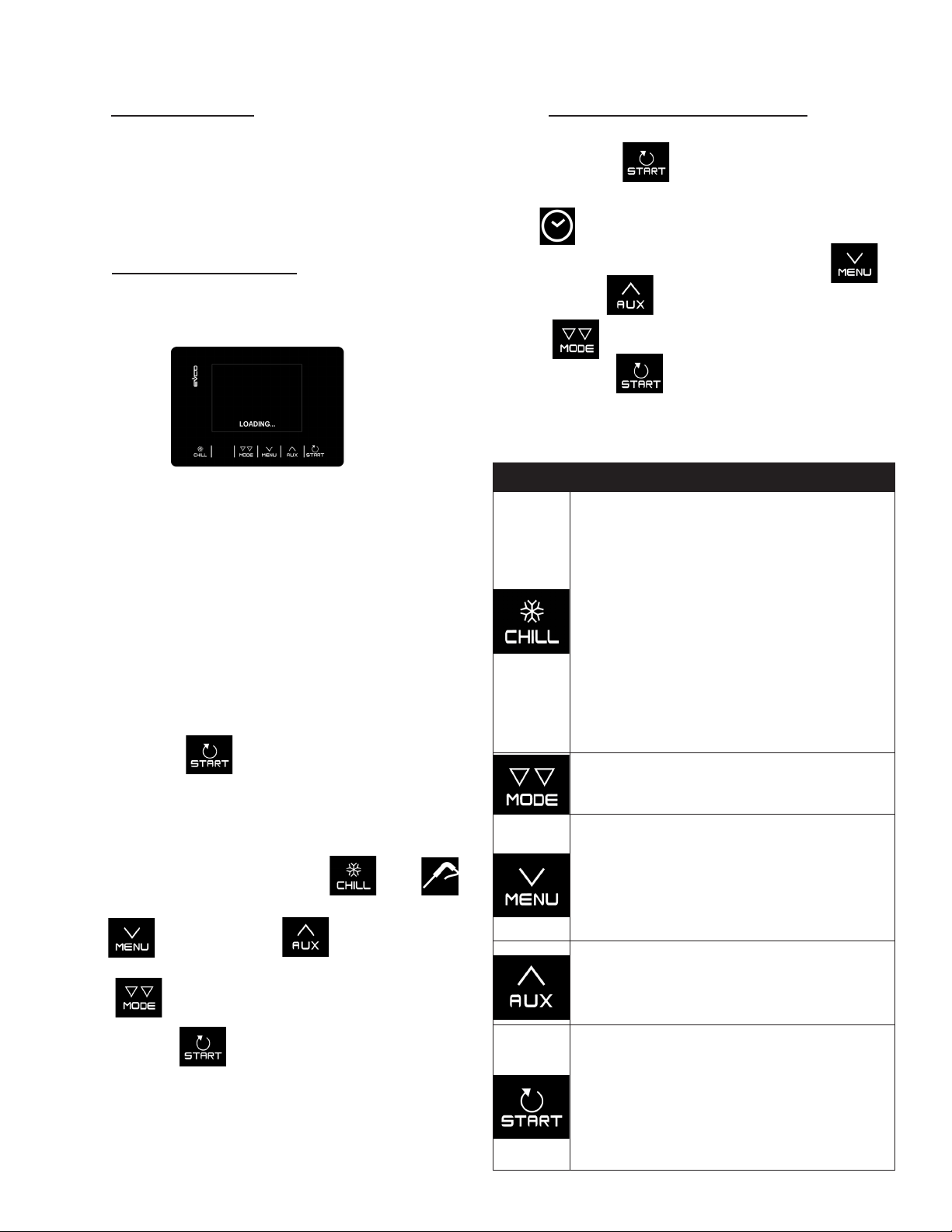
Centerline blast chiller controllers are capable of performing
blast chilling cycles in an intuitive way, both temperature and
time controlled, with hard/soft function. The user interface
has a 2.8 inch color graphic display, and capacitive keys as
shown in gure 12.
VI. b - BASIC OPERATIONS
Initial switch-on:
Once the unit is connected to a power supply, a neutral
system LOADING screen will appear:
Fig. 12
Once loading is complete, the device will display the mode
it was in before being powered down:
• On the home screen with no power failure message;
• Carrying out a cycle with the POWER FAILURE message
indicating that there was a loss of power.
Silencing the buzzer:
To silence the buzzer, touch any key while it is sounding.
Initialization of Temperature Controlled Chill Cycle:
• Press and hold for 3 seconds or until SELECT
CYCLE displays on screen.
• Place probe in product (refer to section IV.c for proper
probe use) and close unit door.
• Set temperature chill by pressing until
displays on screen.
• Use to decrease or to increase chill
temperature.
• Press to select SOFT or HARD chill mode.
• Press and hold for 3 seconds to begin chill cycle.
Blue ashing triangles will appear, indicating the cycle is
in progress.
VI. b - BASIC OPERATIONS (cont’d)
Initialization of Time Controlled Chill Cycle:
• Press and hold for 3 seconds or until SELECT
CYCLE displays on screen.
• The icon will display indicating a default chill cycle
of 240 minutes. To modify chill cycle time, use to
decrease and to increase.
• Press to select SOFT or HARD chill mode.
• Press and hold for 3 seconds to begin chill cycle.
Blue ashing triangles will display, indicating the cycle is
in progress.
Keys & their functions:
KEYS FUNCTION
• Enables the quick selection of a blast
chilling cycle.
• Once a blast chilling cycle has been
selected, it makes it possible to switch
from temperature controlled blast chilling
to time-controlled blast chilling and vice
versa.
• Within a menu or when setting a parameter:
acts as the “ESC” key and returns the
controller to the previous screen.
• When a cycle is in progress the key is not
active; to stop the cycle press the “START”
key for 2 seconds.
• Once the blast chilling cycle has been
selected, it makes it possible to switch from
hard to soft mode and vice versa.
• From the Home page: gives access to the
setting menu.
• Within a menu: enables navigation down
a level.
• During parameter setting: decreases the
value of the element to be modied.
• Within a menu: enables navigation up a
level.
• During parameter setting: increases the
value of the element to be modied.
• Short press: starts the selected function or
gives access to the selected menu page.
• Long press for 2 seconds: interrupts the
cycle in progress.
• During parameter setting: enables the
value to be modified, while pressing a
second time conrms the set value.
-6-
Page 8
VI. CONTROL BASICS (continued)
VI. b - BASIC OPERATIONS (cont’d)
Icons:
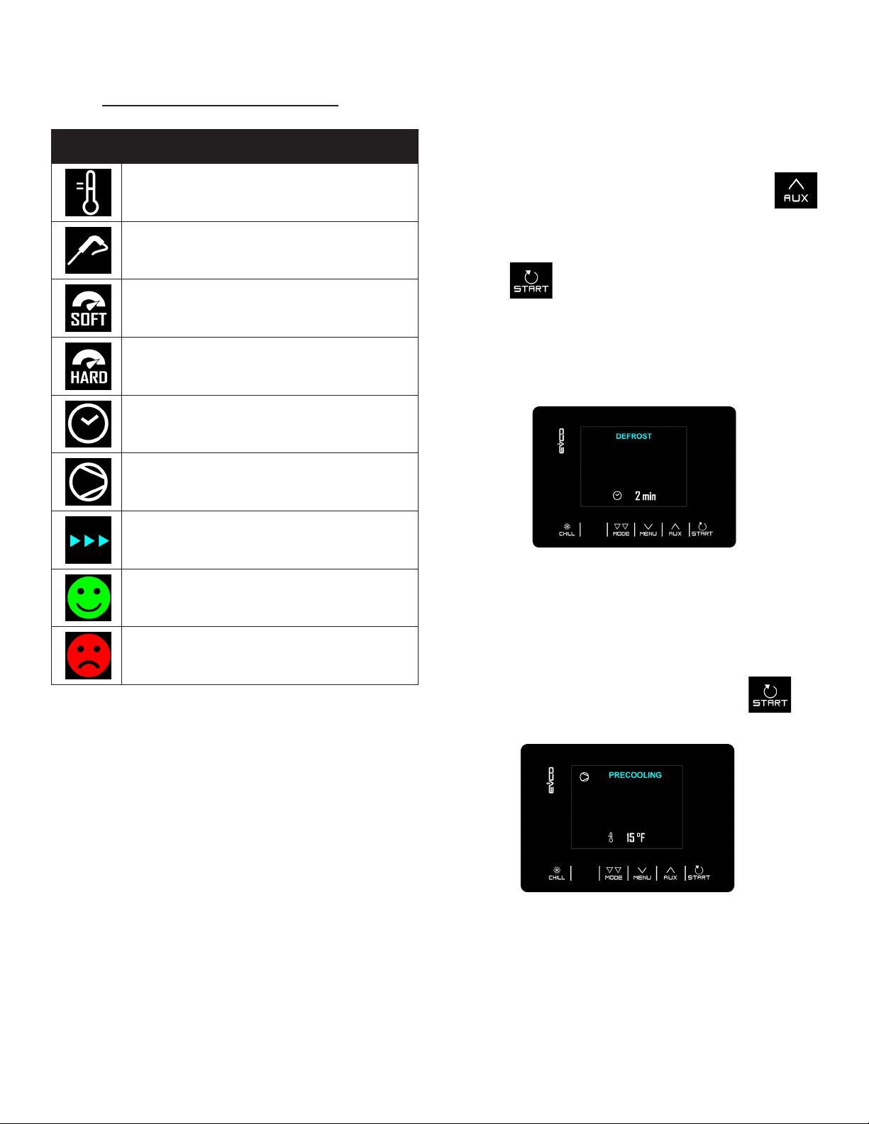
ICON DESCRIPTION
Cabinet temperature
Core temperature
Soft blast chilling
Hard blast chilling
Time-controlled cycle
Compressor output on
VI. c – OTHER FUNCTIONALITIES:
Manual Defrosting:
A defrosting cycle can be initiated manually only if certain
temperature conditions are met.
• Access the SPECIAL CYCLES menu using the
key and select DEFROSTING
• At this point, DEFROSTING will appear and the next
time is pressed, the cycle will start.
• If the conditions for defrosting are not satised, when
the START key is pressed, the device returns to the
SPECIAL CYCLES menu and defrosting is not carried
out.
Cycle in progress
Indicates cycle is complete
Indicates cycle is incomplete
Fig. 13
Pre-Cooling:
This is a refrigeration cycle of innite duration that can
precede all the operating cycles.
It can also be used as a refrigeration cycle of innite duration.
Access the SPECIAL CYCLES menu using the key
and select PRE-COOLING.
Fig. 14
-7-
Page 9
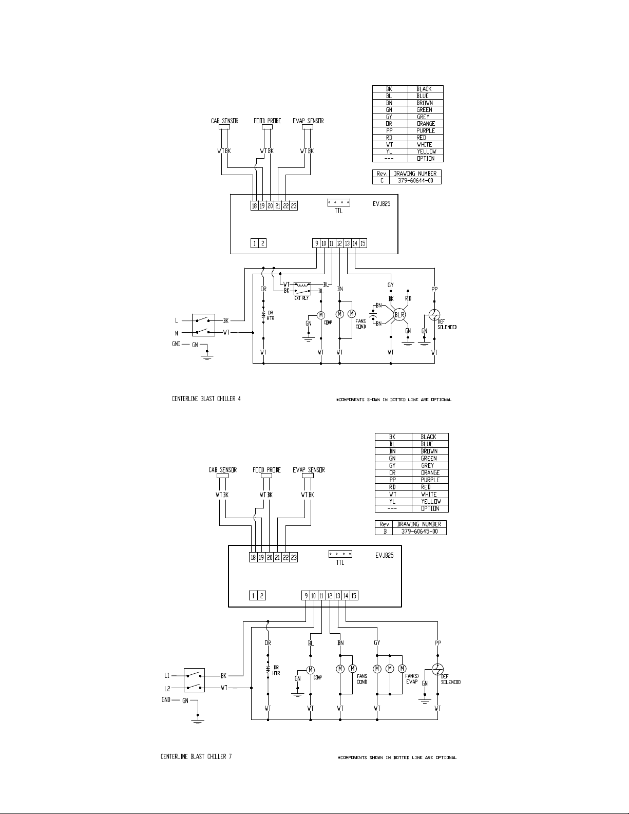
VI. d - WIRING DIAGRAMS:
Undercounter Blast Chiller:
VI. CONTROL BASICS (continued)
Reach-In Blast Chiller:
-8-
Page 10
VI. CONTROL BASICS (continued)
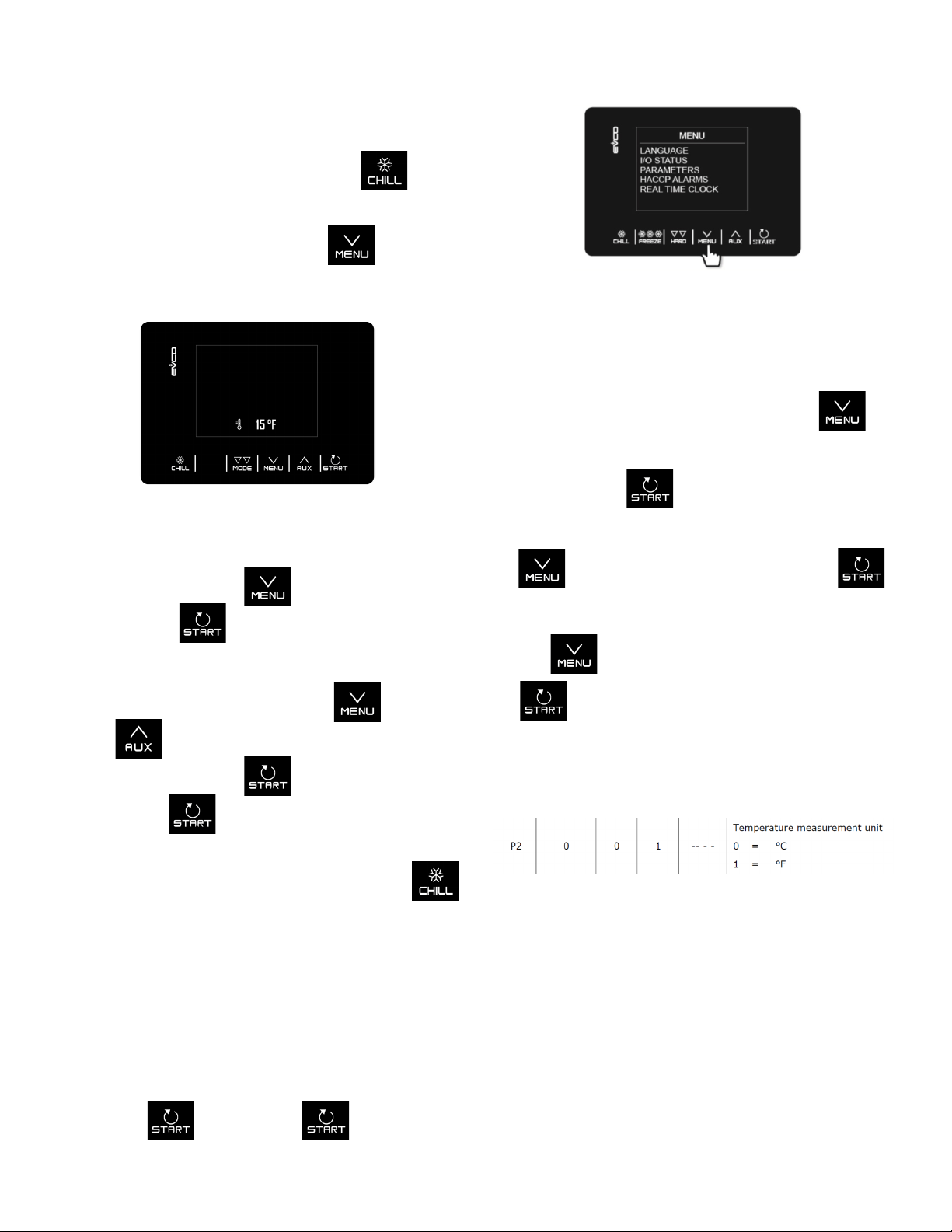
VI. e – CHANGE CONTROL PARAMETERS:
Display the Parameters Menu:
To display the parameters menu, select the key
and cycle through the screens until you come to the
screen in gure 15 and then select the key to
open to the parameters menu.
Fig. 16
Change the Unit of Temperature:
Follow the “Display the Parameters Menu” instructions to
display the parameters menu. Then press the key
and then select the third option “Parameters” shown in gure
Fig. 15
The password must rst be entered to display the
parameters menu. Use the key to decrease from
0 to -19. Use the to key to select the password
“-19”.
To navigate in the parameter menu, use to scroll
down or to scroll up in the menu. To select the
desired parameter with the key to edit it and nally
conrm with the key.
NOTE:
Within the menu or when setting a parameter the
key acts as the “ESC” key and returns the controller to the
previous page.
16 by selecting the key.
The password must rst be entered from the menu using
the key to decrease from 0 to -19. Use the
key to select the password “-19”.
Use the key to scroll down to the “P2” line and use
the key to select the number to change to the desired
temperature unit as shown in gure 17.
Change the Language:
Follow the “Display the Parameters Menu” instructions
to display the parameters menu. Then select the rst
option in the menu “Language” as shown in gure 16 by
selecting the key. Press the key to change
and conrm the desired display language.
-9-
Fig. 17
The parameters are set by default in °F and the relative
values and limits are shown in the table in this unit of
measurement. In order for the controller to display the values
in °C, set P2 to 0 as demonstrated in gure 16 and after the
change, disconnect the power from the device and then
reconnect it. Any previously stored blast chilling programs
will return to the default value each time that the P2 is reset.
Page 11
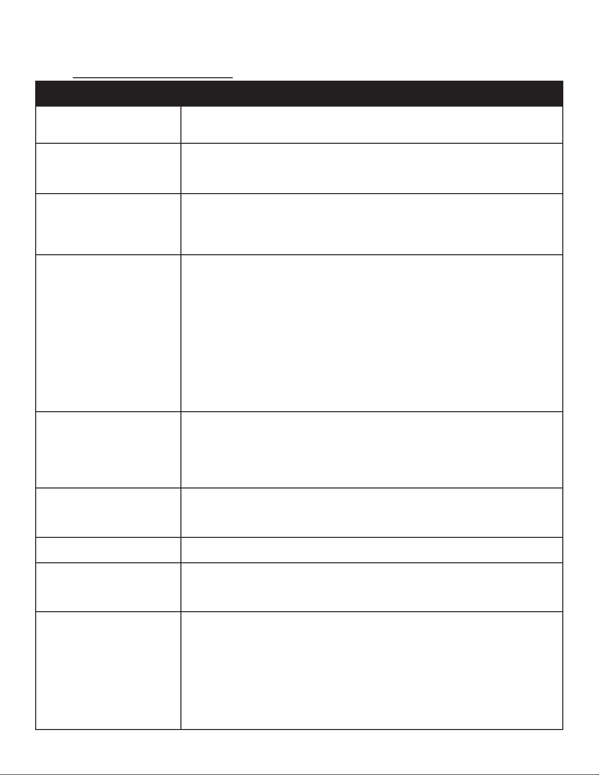
VII. TROUBLESHOOTING GUIDE
VII. a - TROUBLESHOOTING GUIDE
SYMPTOM POTENTIAL CAUSE / SOLUTION
1. No display on control
2. No power on the unit
3. Compressor hums but does
not start
4. Batch requires too much time
to chill product down to target
temperature or time
a. No power to unit / Check power supply and circuit breaker
b. System problem / Call for service
a. Toggle switch is OFF / Turn ON the toggle switch
b. Power cord broken / Check power cord & plug
a. Connected to incorrect power supply / Check if the power connection is to the correct
voltage of power supply; 115v-120v for the undercounter blast chiller and 208V-230V
for the reach-in blast chiller
b. Start component issue / Call for service
a. Door not closed properly / Close door completely
b. Too much product loaded / Adjust the load to not exceed capacity of the unit
c. Product depth in pan exceeds 2” / Reduce pan load
d. Pan has been covered with a lid or plastic wrap or foil, and this is not in direct contact
with the product / Cover product correctly.
e. Product loaded is of a high density / Allow additional chilling time
f. Dirty condenser coil / Clean condenser coil
g. Evaporator coil iced / Allow chiller to defrost
a. Previously chilled product not removed / Remove chilled product before starting a
new chill cycle
5. Unwanted product freezing
6. Need frozen product, not cold
enough
7. Food drying out during chilling a. Food chilled uncovered / Cover food before placing in chiller
8. Condensation on exterior
surface
9. Upon starting a chill cycle,
the product temperature
displayed appears cooler
than expected (cooked)
temperature
b. Chill cycle By Time set for too long / Reduce cycle time
c. High water content food (ex. soup) / Select SOFT CHILL mode
a. This unit is a blast chiller only / For blast freezing needs, contact Traulsen sales
a. Door out of alignment or gasket issue / Check door alignment and gasket for proper
seal
b. Electric door heater malfunction / Call for service
a. Varied product temps within batch / Verify actual product temp using a manual
thermometer
b. Probe placed incorrectly / Relocate probe
c. Small mass product (ex. chicken tender) / Use chill by time
d. Product held at room temperature too long / Verify actual product temperature using
a manual thermometer
-10-
Page 12
VIII. SERVICE/WARRANTY INFORMATION
VIII. a - SERVICE INFORMATION
Before calling for service, please check the following:
Is the electrical cord plugged in?
Is the toggle switch turn ON?
Is the fuse OK or circuit breaker on?
Is the condenser coil clean?
If after checking the above items and the unit is still not operating properly, please contact an authorized Centerline by
Traulsen service agent:
4401 Blue Mound Road Fort Worth, TX 76106
(800) 825-8220.
VIII. b - SPARE PARTS INFORMATION
To purchase replacement parts or to speak to service support for Centerline by Traulsen units please contact our Ft. Worth
facility by phone at 800-825-8220 or fax to 817-740-6748 (parts) or 817-740-6757 (service).
Note: When calling for spare parts or service support, please make sure you have model and serial number of unit available.
Model Number
Serial Number
VIII. c - WARRANTY REGISTRATION:
The warranties for your new Traulsen unit may be registered with us by completing warranty information online, via our
website www.CenterlineFoodEquipment.com. Click on the Product Registration text at the footer of the home page. You
may also register your product by calling us directly at 800-825-8220.
-11-
Page 13
VIII. SERVICE/WARRANTY INFORMATION (continued)
TRAULSEN EQUIPMENT WARRANTY
v. 100215
P/N 375-60359-00 (REV. B)
VIII. d - WARRANTY STATEMENT:
For sales of Traulsen refrigeration equipment (“Equipment”) within the United States, Traulsen warrants to the original
purchaser of the Equipment (“Purchaser”) that Traulsen will convey the Equipment free and clear of all liens, security
interests, and encumbrances created by, through or under Traulsen. Traulsen further warrants that for a period of three (3)
years from the later of either (a) the date of delivery to the common carrier or (b) the date of installation (the “Domestic
Warranty Period”) but in no event, shall the Domestic Warranty Period commence later than 3 months from the date of
delivery to the common carrier unless otherwise agreed upon by the parties in writing, under normal use and given proper
installation and maintenance as determined by Traulsen, the Equipment: (a) will conform to the specifications as provided
by Traulsen (“Specifications”) and (b) will be free from substantial defects in material and workmanship.
The warranty period for compressors shall extend for an additional two (2) years beyond the Domestic Warranty Period. In
the case of a nonconforming compressor, Traulsen shall provide a replacement compressor; however, all installation,
recharging, and repair costs shall be the responsibility of Purchaser. In the case of a nonconforming part, Purchaser must
return the part to Traulsen within 30 days from the date of repair. Failure to return a claimed defective part to Traulsen
within the 30 days will waive the right to the warranty claim.
Additionally, Traulsen provides a lifetime warranty on the housing of cam-lift hinges and the workflow handles. In the case
of a non-conforming housing for cam-lift hinge or workflow handle, Traulsen shall provide a replacement part; however,
Purchaser shall be responsible for any other replacement costs, including but not limited to installation and labor.
The Domestic Warranty does not apply to: (a) consumable components or ordinary wear items; (b) components that are
removable without the use of tools including but not limited to gaskets, shelf pins, and light bulbs; (c) use of the Equipment
components or parts not supplied by Traulsen or specified by Traulsen in the Operator’s Manual as set forth on Traulsen’s
website; or (d) damage resulting from fire, water, burglary, accident, abuse, misuse, transit, acts of God, terrorism, power
surges, improper installation, or repairs or installation by unauthorized third parties. Additionally, the Equipment is intended
only for commercial use and should not be used by consumers or households or in any non-commercial application. This
Domestic Warranty does not apply to, and shall not cover, any Equipment that is installed or used in any way in any
residential or non-commercial application. No warranties, express or implied, are provided to any residential, consumer or
non-commercial purchaser or owner of the Equipment.
For Traulsen units purchased for use with a condenser provided by a third-party,
those components contained within the unit to the point of connection of the refrigeration lines leading to the third-party
condenser.
In the event of a breach of the warranties set forth above (the “Domestic Warranty”), Traulsen will, at Traulsen’s option and
as Purchaser’s sole remedy, repair or replace, including labor costs, any nonconforming Equipment, provided that (a) during
the Warranty Period Traulsen is promptly notified in writing upon discovery of the nonconformance with a detailed
explanation of any alleged deficiencies; (b) Traulsen is given a reasonable opportunity to investigate all claims; and (c)
Traulsen’s examination of any alleged defective part confirms such alleged deficiencies and that the deficiencies were not
caused by misuse, neglect, improper installation, unauthorized alteration or repair or improper testing. Traulsen reserves the
right to, at its request, require Purchaser shall ship the alleged defective part to Traulsen for inspection and confirmation of
defect. No Equipment may be returned without Traulsen’s approval.
Purchaser is solely responsible for determining if Equipment is fit for a particular purpose and suitable for Purchaser’s
application. Accordingly, and due to the nature and manner of Traulsen’s Equipment, Traulsen is not responsible for
the results or consequences of use, misuse, or application of its Equipment.
THIS DOMESTIC WARRANTY SETS FORTH THE EXTENT OF TRAULSEN’S LIABILITY FOR SALES WITHIN
THE UNITED STATES. EXCEPT AS SET FORTH ABOVE, TRAULSEN MAKES NO WARRANTY OR
REPRESENTATION OF ANY KIND, EXPRESS OR IMPLIED (INCLUDING NO WARRANTY OF
MERCHANTABILITY OR FITNESS FOR ANY PARTICULAR PURPOSE). IN NO EVENT WILL TRAULSEN’S
LIABILITY IN CONNECTION WITH THE AGREEMENT OR SALE OF THE EQUIPMENT EXCEED THE
PURCHASE PRICE OF THE EQUIPMENT AS TO WHICH THE CLAIM IS MADE. IN NO EVENT SHALL
TRAULSEN BE LIABLE FOR ANY LOSS OF USE, LOSS OF PRODUCT, LOSS OF PROFIT, OR ANY OTHER
INDIRECT, INCIDENTAL, SPECIAL, OR CONSEQUENTIAL DAMAGES RESULTING FROM THIS WARRANTY
EVEN IF TRAULSEN HAS BEEN NOTIFIED OF THE POSSIBILITY OF SUCH DAMAGES.
U.S. Domestic Warranty
this standard warranty will apply only to
-12-
Page 14

4401 Blue Mound Road Fort Worth, Texas 76106 (USA)
Phone: 800.825.8220 | Service Fax: 817.740.6757 | E-mail: [email protected] | Website: centerlinefoodequipment.com
Form Number: TR36386 | Part Number:375-60376-00 | Revision Date: 08-01-22
Traulsen © All Rights Reserved
 Loading...