

Center OR-P350 User Manual
IR WEATHER-PROOF CAMERA
MANUAL
9. Power cable or videocable should be always loose.
Do not keep the cables tight or twisted.
10. Do not leave the unit along with an unstable stand or table.
11. Please use thecamera unit withingiven temperatureand electricity limit.
12. Pleasemakesure thatinstallation should be done byqualifiedservice
person only.
13. Do not disassemble the unitbyyourself. When there is problem with
the unitplease contact after-sale service centeror the shop where
youb ought.
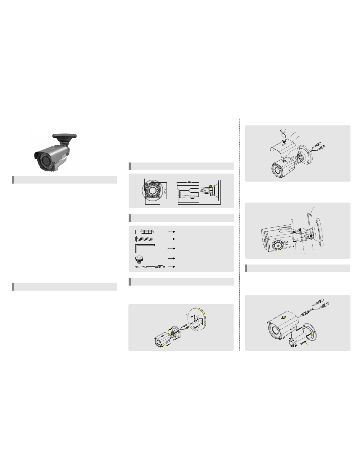
1. Make a hole of Ø25mm in diameter for passing cable.
2. Drill four holes on the wall or ceiling and insert the anchors.
3. Arrange the cables and fix the screws.
ACCESSORIES
DIMENSION
4. Attach the sunvisor and fix the sunvisor fixingbolt.
5. Loosenthe bolt A, C-1 andC-2 by using the3mmwrench included.
6. Face the direction of the camera to monitor.
7. Tighen the bolt A, B, C-1, C-2 to complete adjustment.
1. Attach the bracket to the camera's bottom hole tightly.(In case of
installing the camera on the ceiling, a ttach the bracket to the
sunvisor fixing bolt hole on top of the camera.)
2. Fix the camera and bracket on the wall or ceiling.
1. New generation, new technology Gen DSP adopted.Ⅱ
2. This camera is incredibly flexible to install with its 3-axis camera
construction, which makes the camera ceiling, wall or slope
mountable.
3. Thisproduct is weather-proof to resist rain, snow and other weather
factors(IP66).
4. 40M range visible in total darkness with 40pcs of IR LEDs.(Indoor)
5. Adopted DNRtechnology,It reducesnoise efficiently inlow light condition.
6. Supreme Resolution(600 TV-Line)
7. Day & Night function
8. Support 8 different privacy zone
9. Provide Max. 10x digital zoom
10. DIS(Digital Image stabilizer) relieves anypicturetremble due to external
factor such as wind.
11. LWDR(Low frame Wide Dynamic Range) & DWDR(DigitalWide Dynamic
Range)
12. Dynamic IR : When IR LED is turned on in B/W, the objects can be
clearlyidentified due to thefunction that decreases screen saturation
of objects within a short distance.
13.Multi function : High Light Mask, LensShading Compensation, Motion
Detection
14. Multi-language full OSD support
1. Please study the instruction manual before your applications and
keep it for your future reference.
2. Do not flash LED light directly on the eyes when LEDs are on.
3. Do not install the camera on a unstable surface.
It will cause falling or other hazards.
4. Do not use improper power, it could cause fire or electric shock.
(Use the AC adaptor 12V DC regulated, 1A)
5. Do not disassemble or re-modelth e camera, it could cause fire,
electric shock or other hazards.
6. Stop using the camera when youf ind a malfunction like smoke or
unusual heat, it could cause fire or electric shock.
7. Due to the possibility of water leakage, do not cut or peel off the
cable. In case you cut or peel off the cable, the warranty will be void.
8. Do not adhere dangerous articles to the camera.
CAUTION
FEATURE
HOW TO INSTALL(Built-inbracket type)
HOW TO INSTALL(Stand bracket type - Option)
SCREW, 3EA
WRENCH
BOLT A
BOLT C-2
BOLT C-1
BOLT B
BOLT
SUNVISOR
Ø6
Ø25
ANCHOR 6x30, 4EA
SCREW Tp1 4x35, 4EA
ANCHOR 6x30,4EA
SCREW 4x35 TP1 PAN SUS, 4EA
WRENCH 3mm L TYPE, 1EA
SUNVISOR BOLT, 1EA
Extra video output cablefor installation,
1EA(option)
101.7
206.7
80.4
72
3B15484C※All specification issubject to change without notice toimprovethe quality.
SPECIFICATION
Type 1
Regulated 12VDC ±10%
Type 2
12V DC/24V ACDual voltage
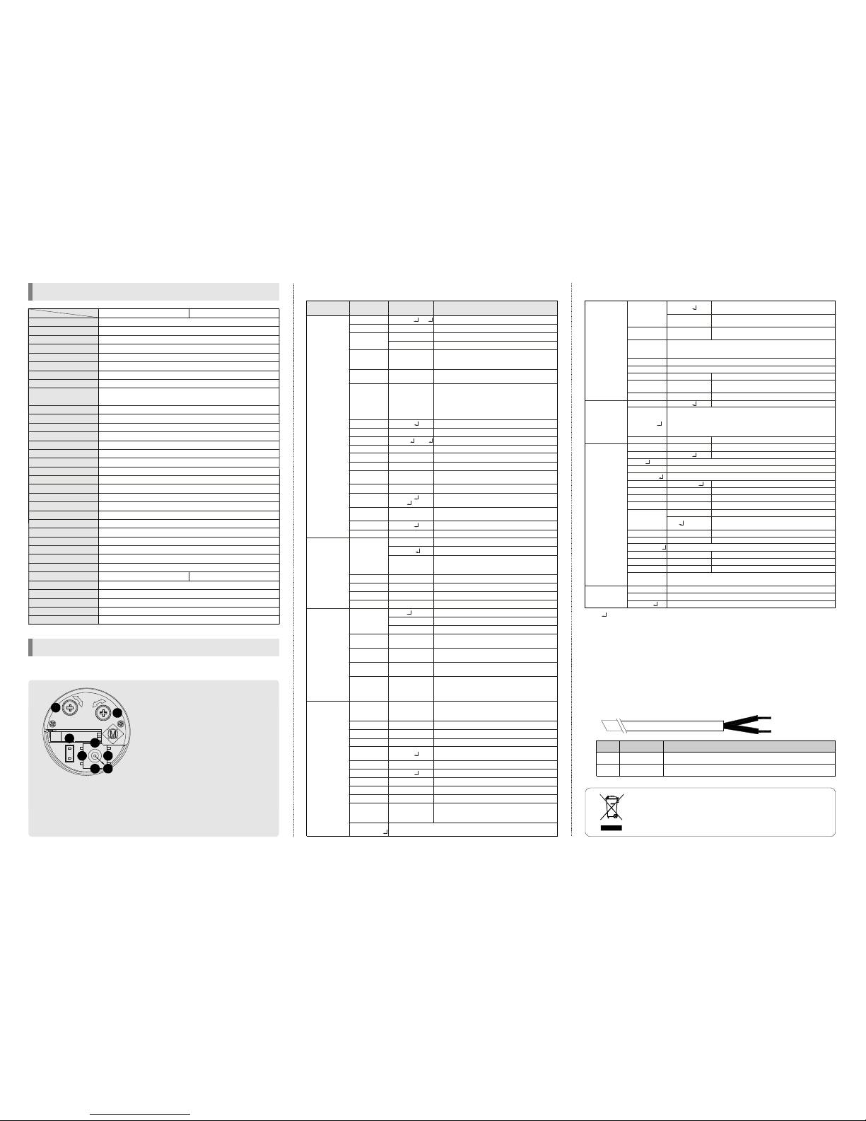
FUNCTION SETTING
1. How to use the jog lever
①ENTER :
② UP, ③DOWN :
④LEFT, ⑤ RIGHT :
⑥ FOCUS, ⑦ZOOM :
⑧ EXT. VIDEO :
Used to access the menu
and confirm selection.
Used to move the
cursor to up or down.
Used to move the
cursor to left or right and change
the value.
Use a '+' type
driver for adjusting zoom and focus.
(In case of operation Focus/Zoom,
don't put stress excessively.)
Extra video output
terminal for installation. The cable is
option.
*OSD menu & Focus/Zoom
adjustment direction
1. Unfasten the screw of the
bottomdoor
2. Adjust the jog lever& Focus
/Zoomtrimmers
3. Tighten the screw of the
bottom door
F
EXT.VIDEO
Z
7
6
8
2
5
13
4
1/3" SONY SUPER HADCCD
768(H)X 494(V)PIX EL(NTSC),752(H) X582(V) PIXEL(PAL)
6.35 (H) X 7.4 (V)(NTSC),6.5 (H) X 6.25 (V)(PAL)
2:1 Interlace
Internal/ Line-Lock(option)
600 TV-LINE(COLOR), 700 TV-LINE(B/W)
52dB orMore(AGC OFF)
1.0 Vp-p(Sync.N egative)Termination 75
γ
= 0.45 typ.(0.45, 0.6, 1.0, user)
Yes(Multi Language)
ATW(2,500°K ~9,500°K)/MANUAL/AWC
1/60(1/50) ~1/100,000sec
Auto(Selectable limit 2X~256X)/FIXED/OFF
BLC, LWDR,DWDR, HLC(ON/OFF)
LOW/MIDDLE/HIGH/OFF
LOW/MIDDLE/HIGH/OFF
ON/OFF(240 Block)
ON/OFF(8 Zone)
H/V/BOTH
ON/OFF
AUTO, COLOR,B/W(Option: ICR)
40pcs,Dynamic IR
ON/OFF
ON(10X)/OFF
AUTO/OFF
RS-485(Protocol :Pelco D,Pelco P)
Vari-focal auto iris lens
Max. 850mA(at 12V DC,24V AC): LED ON
-10℃ ~ 50℃
-20℃ ~ 60℃
80.4(W) X80.7(H) X101.7(D)mm
Approx.900g
Ⅱ
㎛ ㎛ ㎛ ㎛
Ω
0.01Lux(F/1.2), 0.0003Lux(Senseup),
0Lux(40MRange with40pcs LED)- Indoor
Image Sensor
Effective Pixel
Cell Size
ScanningSystem
Sync. Type
Resolution
S/N
Video Output
OSD
Sense up
AGC
DNR(3D)
Gamma
White Balance
ShutterSpeed
Backlight
Motion Detection
PrivacyZone
Mirror
Freeze
Day & Night
LED Brightness
DIS
DigitalZoom
BlemishCompensation
Communication(option)
Lens
PowerSupply
CurrentConsumption
Operation Temp.
Preservation Temp.
Dimension
Weight
Min. Illumination
3. How to control through RS-485 communication(Option)
4. Cable array(Option)
1) Match the camera with controller's ID, baudrate andprotocol
2) Up, Down, Left and right of Jog lever is same as Up, Down, Left and
right of RS-485c ontroller
3) Enter ofJog lever is thesame as menukey orIRIS open key of RS-485
controller
If the product is to be put out of operation definitively,
take it to a local recycling plant for a disposal which
is not harmful to the environment.
Function
RX +
RX -
Remark
RS-485A
RS-485B
No.
A
B
A : ORANGE(RX +)
B : WHITE(RX -)
2. OSD menu structure
0~99
AUTO
OFF, LOW,
MIDDLE,HIGH
OFF,
X2~X256
OFF, ON
OFF, ON
0~20
0~60
0~70
0~100
3~12
OFF, ON
AUTO
0~60
OFF, ON
0~20
ATW
MANUAL
AWC↓
0~255
0~255
0~255
0~255
AUTO
COLOR
B&W
45~160
30~125
3~12
OFF, ON
OFF,
MODE1,
MODE2
OFF, VERT,
HORI, BOTH
0~49
OFF, ON
OFF, ON
0~50
OFF, ON
X1.0~X10
-128~127
-110~109
OFF, ON
Fixed focal lens or Vari-focal auto iris lens
Adjustthe brightness
Shutterspeed autoadjustable
Select shutter speed manually
Determines that use the AGC function or not
and AGC level selectable(You can not use the
Auto D&Nchange modewhen AGCis off)
Using sense upwhen it is lowluminance
(OFF, x2~x256 selectable)
Whenthe Sense-up isactivatedand the camera
detects motion, operates LED and changes to
B/W mode if this mode is activated. Then user
cansee vividimageswithout the afterimage.
(You can set this mode when the camera has
LEDand the D&N modeis set to"Color".)
BLC function
AdjustBLC level
Select LWDR
AdjustWDR level
Using theAuto mode,setthe WDRON brightness
Usingthe Automode, settheWDR OFF brightness
Using the Auto mode, set the WDR switching
delay time
DigitalWide DynamicRange
HighLight Compensation(Usingthe Automode,
theHLC is notactivatedin daylight.)
According to the threshold value, the camera
will recognize asHigh lightor not.
Reducenoise in lowillumination
Levelis selectable
Color temperature2500 ~ 9500°K
Adjustthe Redo rBlue values
Move the camera lens toward to white paper
then press the enter button to find the optimal
white balance for current environment
Adjustthe Redvalueto shiftthecolorof the object
Adjustthe Bluevalueto shiftthecolorof theobject
AdjustRed tone ofthe image
AdjustBlue tone ofthe image
Auto day&night switching mode
Fixed atcolor(LED OFF)
Fixed atB/W(LED level selectable)
Select brightness of illuminationabout changing
theday ↔ nightmode
Select the duration time about changing the
day ↔night mode
Determines whetherto transmit theburst signal
or not inB/W mode
When IRLED is turned on in B/W, the objects
can be clearly identified due to the function
that decreases screen saturation of objects
within ashort distance.
VERT :S eta verticalimage inversion
HORI : Seta horizontal image inversion
BOTH: set aimage rotation
Sharpness adjustable
Gamma adjustable
Get astill image
Determines whether to use the brightness
compensation offour lens' corners(LSC)or not
The LSC level selectable
Max10x digitalzoomavailable(Defaultvalueis X3)
Digitalzoom adjustable
Zoomed inimage can bemoved tohorizontal
Zoomed inimage can bemoved tovertical
Thisfunctioncan bemitigatesimage movement
from external factors(This function uses digital
zoom)
LENS
LEVEL
E.SHUTTER
AGC
SENSE UP
ANTIGHOST
BLC
LEVEL
LWDR
LEVEL
OFF→ON
ON→OFF
DELAY TIME
DWDR
HLC
LEVEL
DNR
LEVEL
WB MODE
R-Y GAIN
B-Y GAIN
D&N MODE
DELAY TIME
BURST
DYNAMICIR
FLIP
SHARPNESS
GAMMA
FREEZE
LSC
LEVEL
DZOOM
ZOOM
PAN
TILT
DIS
Function
settingmenu
Select menu ContentsSub menu
MANUAL , DC
1/60(1/50)~1/100,000
MANUALB LUE
MANUALRED
BW COLOR→
COLOR BW→
0.45, 0.6,1, USER
1. EXPOSURE
3. DAY&NIGHT
4. IMAGEADJ.
2. WHITE
BALANCE
PAT TERN
GENERATOR
Test signal. Press the enter button, color bar appeared on the
screenand pressany keyto returnto menu.
Determineswhetherto usethe motion detection
function ornot
No display onthe screenthough movement is
detected
Thewords'MOTION'appearon thescreenwhen
movementis detected
Motion detection sensitivity
Setthe duration of alarm out. Iftheway ofdisplay
ismessage,it meansdisplaytime ofmessage
Not available
Displayeach privacymask or not
Select maskcolor(8 color isavailable)
Select language
Displaythe cameraID on the screen
Defectpixel correction inl owillumination
Setupthe limitedvalue ofwhite pixel correction
Setupthe limited value ofblack pixel correction
Setup theDPC(Defect PixelCorrection)level
InternalSync with 12VDC power
Setting the phase is selectable when used
24V AC(Dualpower only)
Phase contollable at24V AC input(L/L mode)
Monitorsetting
Select thecamera IDforRS-485communication
Select baud rate
Select protocol
OFF, ON
NONE
MESSAGE
0~120
1~15
OFF
OFF, ON
BLACK,GRAY…
ENGLISH,…
OFF, ON
OFF, AUTO
0~255
0~255
0~255
INT
L/L
0~255
CRT, LCD
1~255
MOTION
DISPLAY
SET
WINDOW
ALL SET↓
SENSITIVITY
HOLD TIME
IMPACT
MASK 1 ~8
SET
WINDOW
COLOR SET
LANGUAGE
TITLE
EDIT
RESET↓
POSITION
DPC
WHITE THR
BLACKTHR
DPC LEVEL
SYNC
VPHASE
MONITOR
COM. ID
BAUDRATE
PROTOCOL
FACTORY
SET↓
EXIT↓
RETURN
7. SPECIAL
6.PRIVACY
ZONE
8. EXIT
2400, 4800, 9600
PELCO-D,PELCO-P
COMMUNICATION
SAVE AND EXIT↓
ALL CLEAR↓
5. ALARM
Pressthe enterbuttonto moveintothe motiondetectionareasection
toset the 240 blocks.Toescapethis menu,you shouldpresstheleft
buttonat the far leftor presstherightbuttonat the farright.
Press the enterbutton toselect all area
Press the setbutton to remove allarea
Press the enter button at first time, you can move the mask's
position. After press the enter button again, you can adjust the
size of mask. If you press the set button once more, you can
adjust position of edge. After decided position of edge then
pressthe enterbutton, itwill beback topreviousmenu.
CameraID setting
CameraID reset
CameraID position
Communication setting(option)
Reset your camera tofactory default conditionand then restart
Notice :Lens, communication andlanguage isnot changed
Save thevalue andthen restart
Escapethe menu without save
Moveback to previousmenu
ㆍThe ' ' icon appeared with desired function, press the set button to move sub menu.
ㆍThe '-- -' iconappeared withfunction thatis unavailable according tofunction setting.
OFF, LOW, MIDDLE, HIGH
OFF, ON , AUTO
 Loading...