

Center CenterStore Solar Series Servicing Installation And Servicing Instructions

Solar
For latest prices and delivery to your door visit MyTub Ltd - www.mytub.co.uk - info@mytub.co.uk 0844 556 1818
UNVENTED MAINS PRESSURE SOLAR WATER HEATERS
190, 210, 250 and 300 LITRE CAPACITY INDIRECT MODELS
INSTALLATION AND SERVICING INSTRUCTIONS
PACK CONTENTS
The CENTERSTORE Solar unvented solar cylinder water heater incorporating immersion heater(s) and thermal
controls Factory fi tted temperature/pressure relief valve l Cold water combination valve assembly l Expansion
vessel and mounting bracket l Tundish l Motorised valve l Compression nuts and olives l Immersion heater spanner
l Installation instructions
IMPORTANT: PLEASE READ AND UNDERSTAND ALL THESE INSTRUCTIONS
BEFORE COMMENCING INSTALLATION. PLEASE LEAVE THIS MANUAL WITH
THE CUSTOMER FOR FUTURE REFERENCE.
THE BENCHMARK SCHEME
Benchmark places responsibilities on both manufacturers and installers. The purpose is to ensure that customers
are provided with the correct equipment for their needs, that it is installed, commissioned and serviced in
accordance with the manufacturer’s instructions by competent persons and that it meets the requirements of
the appropriate Building Regulations. The Benchmark Checklist can be used to demonstrate compliance with
Building Regulations and should be provided to the customer for future reference.
Installers are required to carry out installation, commissioning and servicing work in accordance with the Benchmark
Code of Practice which is available from the Heating and Hotwater Industry Council who manage and promote
the Scheme. Visit www.centralheating.co.uk for more information.
IMPORTANT NOTE TO USER: PLEASE REFER TO THE USER INSTRUCTIONS SECTION ON PAGES 14 AND 15 FOR
IMPORTANT INFORMATION WITH RESPECT TO THE BENCHMARK SCHEME
INTRODUCTION
The CENTERSTORE Solar cylinder is a purpose designed unvented solar water heater. The unit has a
stainless steel inner vessel, which ensures an excellent
standard of corrosion resistance. The outer casing is a
combination of resilient thermoplastic mouldings and
corrosion proofed steel sheet. All products are insulated with CFC/HCFC free polyurethane foam to meet the
latest European heat loss requirements (see Table 6).
The unit is supplied complete with all the necessary
safety and control devices needed to allow connection
to the cold water mains. All these components are
preset and not adjustable.
This appliance complies with the requirements of the
CE marking directive and is Kiwa approved to show
compliance with Building Regulations (Section G3).
The following instructions are offered as a guide to
installation which must be carried out by a competent
plumbing and electrical installer in accordance with
Building Regulation G3, The Building Standards
(Scotland) Regulations 1990, or The Building Regulations (Northern Ireland).
NOTE: Prior to installation the unit should be stored in
an upright position in an area free from excessive damp
or humidity.
1
1

Contents
For latest prices and delivery to your door visit MyTub Ltd - www.mytub.co.uk - info@mytub.co.uk 0844 556 1818
INTRODUCTION.................................................................1
GENERAL REQUIREMENTS.............................................3
INSTALLATION-GENERAL...............................................4
INSTALLATION - SOLAR PRIMARY...............................9
INSTALLATION - AUXILLARY HEATING COIL...........10
COMMISSIONING.............................................................12
MAINTENANCE..................................................................13
PA GE
USER INSTRUCTIONS.......................................................14
FAULT FINDING AND SERVICING.................................15
OTHER INFORMATION.....................................................17
ENVIRONMENTAL INFORMATION...............................17
COMMISSIONING CHECK LIST......................................18
SERVICE RECORD..............................................................19
GUARANTEE.......................................................................20
TECHNICAL SUPPORT AND SPARES...........................20
2
IMPORTANT: THIS APPLIANCE IS NOT INTENDED
For latest prices and delivery to your door visit MyTub Ltd - www.mytub.co.uk - info@mytub.co.uk 0844 556 1818
FOR THE USE BY PERSONS (INCLUDING CHILDREN)
WITH REDUCED PHYSICAL, SENSORY OR MENTAL
CAPABILITIES, OR LACK OF KNOWLEDGE AND EXPERIENCE, UNLESS THEY HAVE BEEN GIVEN SUPERVISION OR INSTRUCTION CONCERNING THE USE OF
THE APPLIANCE BY A PERSON RESPONSIBLE FOR
THEIR SAFETY. CHILDREN MUST BE SUPERVISED.
GENERAL REQUIREMENTS
SITING THE UNIT
The CENTERSTORE Solar must be installed vertically.
Although location is not critical, the following points
should be considered:
• The CENTERSTORE Solar should be sited to ensure minimum dead leg distances, particularly
to the point of most frequent use.
• Avoid siting where extreme cold temperatures
will be experienced. All exposed pipework
should be insulated.
• The discharge pipework from the safety valves
must have minimum fall of 1:200 from the unit
and terminate in a safe and visible position.
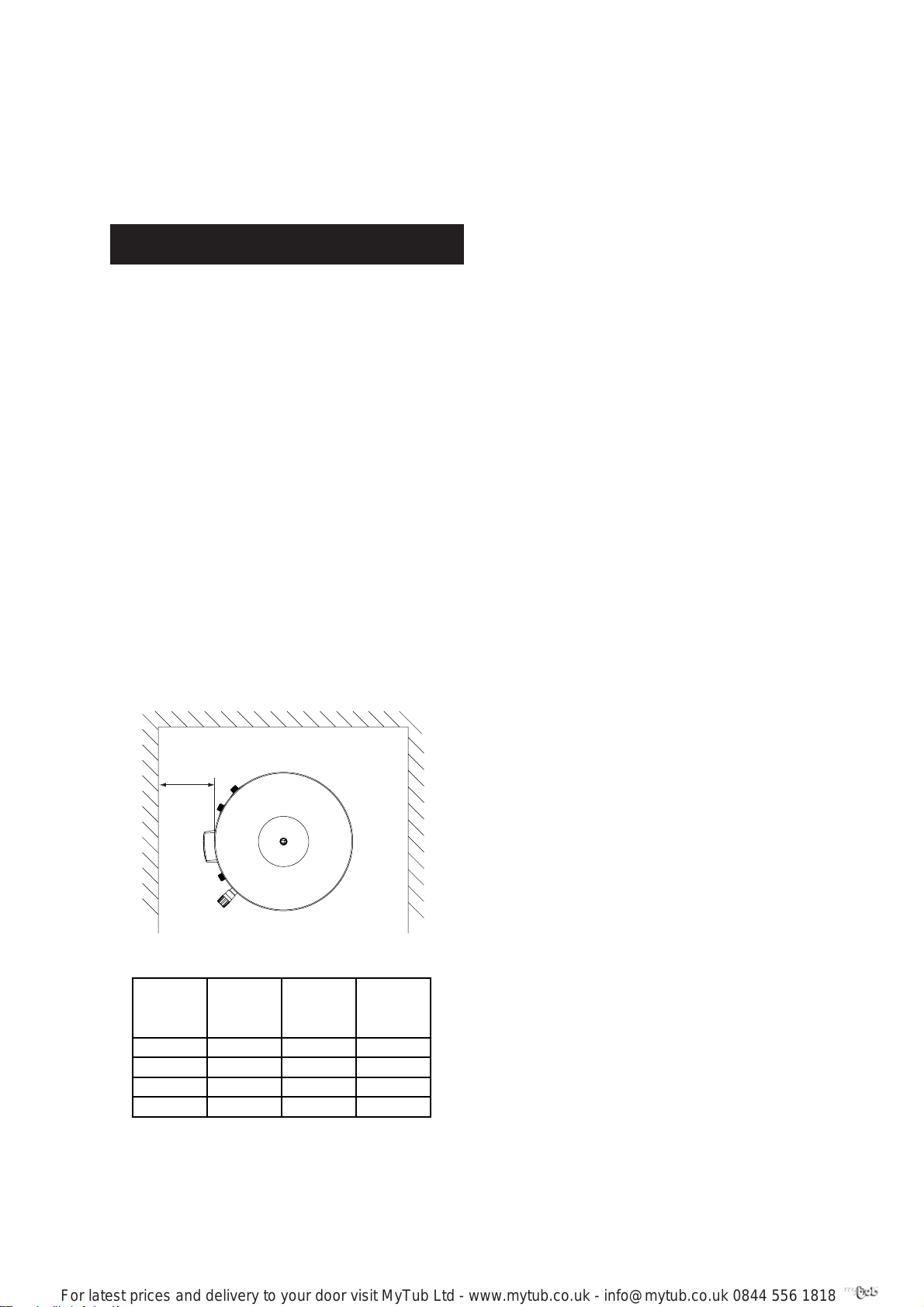
• Access to associated controls and immersion
heaters must be available to provide for the
servicing and maintenance of the system.
Where these controls are installed against a wall
a minimum distance of 250mm must be left (see
Fig. 1).
• Ensure that the fl oor area for the CENTERSTORE
Solar cylinder is level and capable of perman ently supporting the weight when full of water.
(See Table 1).
Min 250mm
Fig. 1: Siting the Unit
Type
reference
INDIRECT SCS190I 190 240
SCS210I 210 264
SCS250I 250 308
SCS300I 300 367
Table 1: Unit weights
WATER SUPPLY
Bear in mind that the mains water supply to the property
will be supplying both the hot and cold water requirements simultaneously. It is recommended that the
Model
WALL
Nominal
capacity
(litres)
Weight of
unit full
(kg)
maximum water demand is assessed and the water
supply checked to ensure this demand can be satisfactorily met.
Note: A high mains water pressure will not always
guarantee high fl ow rates.
Wherever possible the mains supply pipe should be
22mm. We suggest the minimum supply requirements
should be 1.5 bar pressure and 20 litres per minute fl ow
rate. However, at these values outlet fl ow rates may be
poor if several outlets are used simultaneously. The
higher the available pressure and fl ow rate the better
the system performance.
The CENTERSTORE Solar cylinder has an operating pressure of 3.5 bar which is controlled by the cold water
combination valve assembly. The cold water combination
valve assembly can be connected to a maximum mains
pressure of 16 bar.
OUTLET/TERMINAL FITTINGS (TAPS, ETC.)
The CENTERSTORE Solar cylinder can be used with
most types of terminal fi ttings. It is advantageous in
many mixer showers to have balanced hot and cold
water supplies. In these instances a balanced pressure
cold water connection should be placed between the
2 pieces of the cold water combination valve assembly
(see Fig. 2). Outlets situated higher than the CENTERSTORE Solar cylinder will give outlet pressures lower
than that at the heater, a 10m height difference will
result in a 1 bar pressure reduction at the outlet. All
fi ttings, pipework and connections must have a rated
pressure of at least 6 bar at 80°C.
LIMITATIONS
The CENTERSTORE Solar cylinder should not be used in
association with any of the following:
• Solid fuel boilers or any other boiler in which the
energy input is not under effective thermostatic
control unless additional and appropriate safety
measures are installed.
• Ascending spray type bidets or any other class
1 back syphonage risk requiring that a type A
air gap be employed.
• Steam heating plants unless additional and
appropriate safety devices are installed.
• Situations where maintenance is likely to be
neglected or safety devices tampered with.
• Water supplies that have either inadequate
pressure or where the supply may be intermittent.
• Situations where it is not possible to safely pipe
away any discharge from the safety valves.
• In areas where the water consistently contains a
high proportion of solids, e.g. suspended matter
that could block the strainer, unless adequate
fi ltration can be ensured.
OPERATIONAL SUMMARY
Maximum mains pressure 16 bar
Operating pressure 3.5 bar
Expansion vessel charge pressure 3.5 bar
Expansion relief valve setting 6 bar
T&P relief valve setting 90°C/10
Maximum primary circuit pressure
(auxillary coil) 3 bar
Maximum primary circuit pressure 6 bar
Storage capacity See Table
Weight when full See Table
bar
(solar coil)
1
1
3
3
IMPORTANT NOTE:
For latest prices and delivery to your door visit MyTub Ltd - www.mytub.co.uk - info@mytub.co.uk 0844 556 1818
CENTERSTORE SOLAR MUST BE INCORPORATED
INTO A FULLY PUMPED SOLAR PRIMARY CIRCUIT.
CONTROL OF THE SOLAR PRIMARY IS ACHIEVED BY
THE USE OF EXTERNAL CONTROLS NOT SUPPLIED
WITH THE UNIT. CONTROL MUST BE VIA A PURPOSE
DESIGNED SOLAR HYDRAULIC STATION AND SOLAR
DIFFERENTIAL TEMPERATURE CONTROLLER.
DRAIN TAP
A suitable draining tap should be installed in the
cold water supply to the CENTERSTORE Solar cylinder
unit between the expansion valve (see Fig. 6) and the
heater at as low a level as possible. It is recommended
that the outlet point of the drain pipework be at least
1 metre below the level of the heater (this can be
achieved by attaching a hose to the drain tap outlet
spigot).
INSTALLATION - GENERAL
(FIGS 4 & 6)
PIPE FITTINGS
All pipe fi ttings are made via 22mm compression
fi ttings directly to the unit. The fi ttings are threaded
3/4”BSP male parallel should threaded pipe connections be required.
COLD FEED
A 22mm cold water supply is recommended, however
if a 15mm (1/2”) supply exists which provides suffi cient
fl ow this may be used (although more fl ow noise may
be experienced).
A stopcock or servicing valve should be incorporated
into the cold water supply to enable the CENTERSTORE
Solar cylinder and its associated controls to be isolated
and serviced.
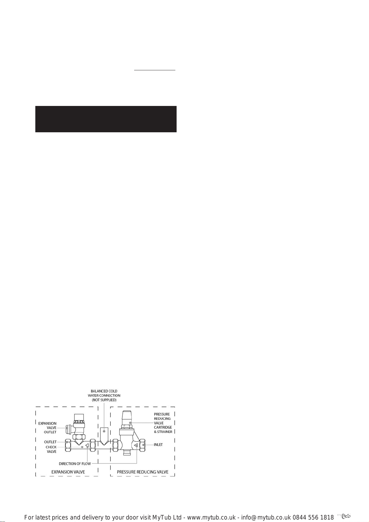
COLD WATER COMBINATION VALVE ASSEMBLY (FIG 2)
The 2-piece cold water combination valve assembly
can be located anywhere on the cold water mains
supply prior to the expansion vessel (see Fig. 6) but the
two pieces do not have to be installed together. The
pressure reducing valve incorporates the pressure
reducer & strainer and the expansion valve incorporates the expansion & check valves. Ensure that the
valves are installed in the correct order and orientation.
No other valves should be placed between the expansion valve and the CENTERSTORE Solar unit. A connection can be made between the expansion and pressure reducing valves to provide a balanced cold water
connection. The expansion valve connection must not
be used for any other purpose.
EXPANSION VESSEL
The expansion vessel accommodates expansion that
results from heating the water inside the unit. The
expansion vessel is pre-charged at 3.5 bar. The expansion vessel must be connected between the expansion valve (see Fig. 2) and the CENTERSTORE Solar
cylinder (see Fig. 6). The location of the expansion
vessel should allow access to recharge the pressure as
and when necessary, this can be done using a normal
car foot pump. It is recommended that the expansion
vessel is adequately supported. An expansion vessel
wall mounting bracket is supplied for this purpose and
should be fi tted.
NOTE: DO NOT USE THE POTABLE WATER EXPANSION VESSEL SUPPLIED WITH THE CENTERSTORE
SOLAR CYLINDER FOR ANY OTHER PURPOSE. IT
IS NOT SUITABLE FOR USE ON A SOLAR PRIMARY
CIRCUIT.
SECONDARY CIRCULATION
If secondary circulation is required it is recommended
that it be connected to the CENTERSTORE Solar cylinder
as shown in Fig. 3. The secondary return pipe should be
in 15mm pipe and incorporate a check valve to prevent
backfl ow. A suitable WRAS approved bronze circulation
pump will be required. On large systems, due to the increase in system water content, it may be necessary to fi t
an additional expansion vessel to the secondary circuit.
This should be done if the capacity of the secondary
circuit exceeds 10 litres.
Pipe capacity (copper)
15mm O.D = 0.13 l/m (10 litres = 77m)
22mm O.D = 0.38 l/m (10 litres = 26m)
28mm O.D = 0.55 l/m (10 litres = 18m)
OUTLET
The hot water outlet is a 22mm compression fi tting
located at the top of the cylinder. Hot water distribution pipework should be 22mm pipe with short runs
of 15mm pipe to terminal fi ttings such as sinks and
basins. Pipe sizes may vary due to system design.
Fig. 2: Cold water combination valve assembly
4
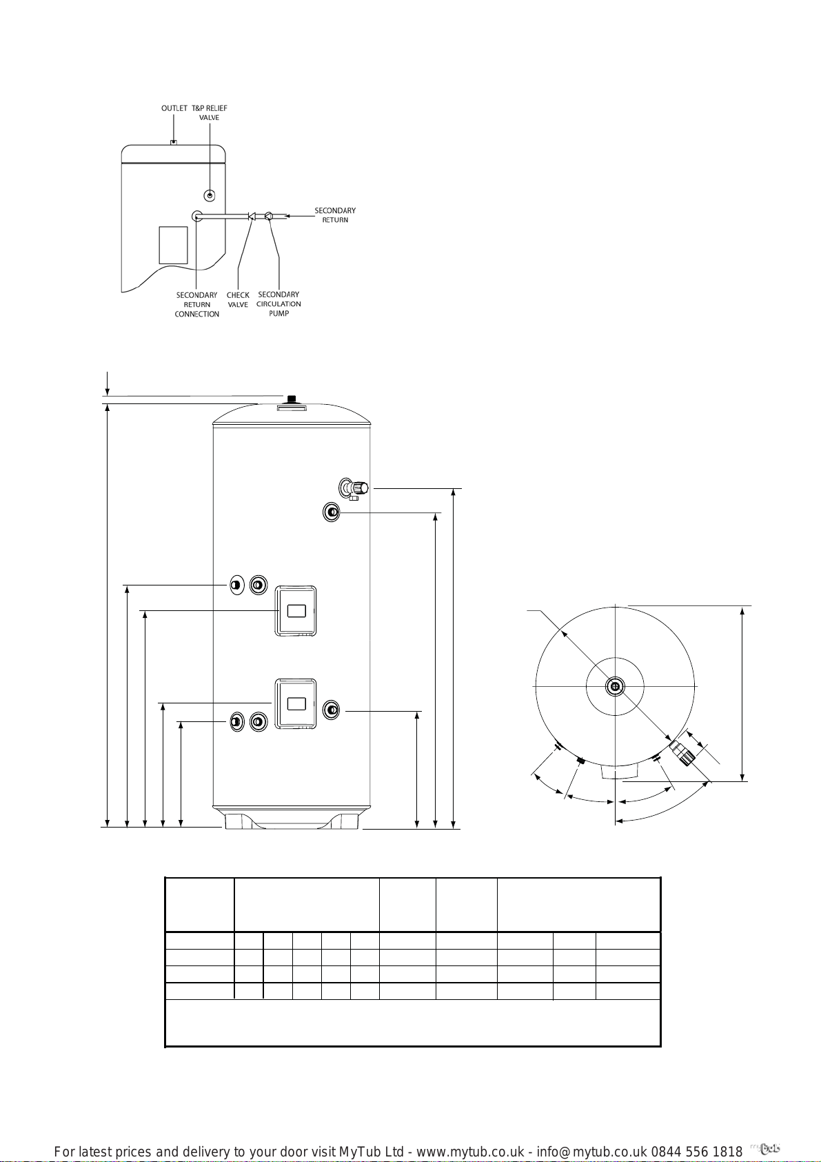
Fig. 3: Secondary circulation connection
For latest prices and delivery to your door visit MyTub Ltd - www.mytub.co.uk - info@mytub.co.uk 0844 556 1818
29
A
C
B
370
433
Fig. 4: General dimensions
NOMINAL
CAPACITY
(litres)
190
250
300
1372 803 923732 1019
210
1473 925 1095
1731 1072 12581160 1391 1.1
2038 1243 15731438 1715 1.1
NOTES:
1. Recovery time based on heating 70% of auxillary volume through 45°C
2. Direct heating times assume use of lower element only and auxillary cylinder volume being heated.
DIMENSIONS (mm)
ABCDE
1009
1184 1.1
412
SOLAR
SURFACE
AREA (m)
1.1
E
D
AUXILLARY
VOLUME
(litres)
120
120
145
175
Ø
550
20°
SURFACE
AREA
(m
)
0.61
0.68 18.3 17
0.79 20.0
0.79
AUXILLARY COIL
RATING
(kW)
11.9
20.0
25°
594
81
30°
45°
RECOVERY
(mins)
22
19
22
Table 2: Dimensions and performance
5
5

DISCHARGE PIPEWORK
For latest prices and delivery to your door visit MyTub Ltd - www.mytub.co.uk - info@mytub.co.uk 0844 556 1818
It is a requirement of Building Regulation G3 that any
discharge from an unvented system is conveyed to
where it is visible, but will not cause danger to persons
in or about the building. The tundish and discharge
pipes should be fi tted in accordance with the requirements and guidance notes of Building Regulation G3.
The G3 Requirements and Guidance section 3.9 are
reproduced in the following sections of this manual.
Information Sheet No. 33 available from the British
Board of Agrément gives further advice on discharge
pipe installation. For discharge pipe arrangements not
covered by G3 Guidance or BBA Info Sheet No.33
advice should be sought from your local Building
Control Offi cer.
Any discharge pipe connected to the pressure relief
devices (Expansion Valve and Temperature/Pressure Relief Valve) must be installed in a continuously
downward direction and in a frost free environment.
The water may drip from the discharge pipe of the
pressure relief device. This pipe must be left open to
the atmosphere. The pressure relief device is to be operated regularly to remove lime deposits and to verify
that it is not blocked.
G3 REQUIREMENT
“...there shall be precautions...to ensure that
the hot water discharged from safety devices is
safely conveyed to where it is visible but will not
cause danger to persons in or about the building.”
G3 GUIDANCE SECTION 3.9
The discharge pipe (D1) [see fi g. 5 in this instruc-
tion book] from the vessel up to and including
the tundish is generally supplied by the manufacturer of the hot water storage system. Where
otherwise, the installation should include the
discharge pipe(s) (D1) from the safety device(s).
In either case the tundish should be vertical,
located in the same space as the unvented hot
water storage system and be fi tted as close as
possible and within 500mm of the safety device
e.g. the temperature relief valve.
The discharge pipe (D2) from the tundish should
terminate in a safe place where there is no risk
to persons in the vicinity of the discharge, preferably be of metal and:
a. be at least one pipe size larger than the
nominal outlet size of the safety device unless its
total equivalent hydraulic resistance exceeds that
of a straight pipe 9m long i.e. discharge pipes
between 9m and 18m equivalent resistance
length should be at least two sizes larger than
the nominal outlet size of the safety device,
between 18 and 27m at least 3 sizes larger ,
and so on. Bends must be taken into account
in calculating the fl ow resistance. Refer to Table
3, Table 1 and the worked example [see Table 3
and Fig. 5 in this instruction book].
use within buildings and their curtilages, Appendix E, section E2 and table 21.
b. have a vertical section of pipe at least 300mm
long, below
bends in the pipework.
c. be installed with a continuous fall and in a
frost free environment.
d. have discharges visible at both the tundish
and the fi nal point of discharge but where this
is not possible or is practically diffi cult there
should be clear visibility at one or other of these
locations. Examples of acceptable discharge
arrangements are:
Worked example of discharge pipe sizing
Fig. 5 is for a G1/2 temperature relief valve with a discharge pipe (D2) having 4 No. elbows and length of 7m
from the tundish to the point of discharge.
the tundish before any elbows or
i. ideally below a fi xed grating and above the
water seal in a trapped gully.
ii. downward discharges at low level; i.e. up
to 100mm above external surfaces such as
car parks, hard standings, grassed areas etc.
are acceptable providing that where children
may play or otherwise come into contact with
discharges a wire cage or similar guard is positioned to prevent contact, whilst maintaining
visibility.
iii. discharges at high level; e.g. into a metal
hopper and metal down pipe with the end
of the discharge pipe clearly visible (tundish
visible or not) or onto a roof capable of
withstanding high temperature discharges
of water and 3m from any plastics guttering
system that would collect such discharges
(tundish visible).
iv. where a single pipe serves a number of
discharges, such as in blocks of flats, the
number served should be limited to not
more than 6 systems so that any installation
discharging can be traced reasonably easily.
The single common discharge pipe should be
at least one pipe size larger than the largest
individual discharge pipe (D2) to be connected. If unvented hot water storage systems
are installed where discharges from safety
devices may not be apparent i.e. in dwellings
occupied by blind, infi rm or disabled people,
consideration should be given to the installation of an electronically operated device to
warn when discharge takes place.
Note: The discharge will consist of scalding
water and steam. Asphalt, roofi ng felt and
non-metallic rainwater goods may be
damaged by such discharges.
An alternative approach for sizing discharge
pipes would be to follow BS 6700:1987 Specifi cation for design installation, testing and maintenance of services supplying water for domestic
From Table 3:
Maximum resistance allowed for a straight length of
22mm copper discharge pipe (D2) from a G1/2 temperature relief valve is 9.0m.
6
 Loading...