

Center 265 Operating Manual
Center 265 Leakage Current Clamp Meter
Operating Manual

Center 265 True RMS Leakage Current Clamp Meter
1
TABLE OF CONTENTS
1. SAFETY INFORMATION .................................................................... 1
2. GENERAL SPECIFICATIONS ............................................................... 1
3. ELECTRICAL SPECIFICATIONS .......................................................... 2
3-1 AC mA Measurement ....................................................................... 2
3-2 AC A Measurement .......................................................................... 3
3-3 AC V Measurement .......................................................................... 3
3-4 DC V Measurement .......................................................................... 3
3-5 CONTINUITY ( ) .................................................................................. 3
3-6 RESISTANCE(Ω). ............... .................................................................... 3
4. DESCRIPTION OF THE INSTRUMENT .............................................. 4
4-1 Description of the display ................................................................. 4
4-2 Description of front and rear ............................................................ 5
5. BUTTON INSTRUCTION ..................................................................... 6
5-1 HOLD & LPF Function ........................................................................ 6
5-2 PEAK HOLD Function ........................................................................ 6
5-3 ZERO Function .................................................................................. 6
5-4 BACKLIGHT Function ........................................................................ 6
6. MEASURING INSTRUCTION ............................................................. 7
6-1 AC A & AC mA Measurement ............................................................ 7
6-2 AC V Measurement .......................................................................... 8
6-3 DC V Measurement .......................................................................... 9
6-4 Continuity Measurement ................................................................. 9
6-5 Resistance Measurement ................................................................10
7. BATTERY CHANGING ........................................................................10
8. MAINTENANCE ..................................................................................11
Clamp Meter
2
1. SAFETY INFORMATION
1. Do not operate the tester if there is any sign of damage to the
tester or the test leads.
2. Check the main function dial and make sure it is in the correct
position before each measurement.
3. Do not perform resistance and continuity tests on a live power
system.
4. Do not apply voltage between the test terminals and test
terminal to ground that exceed the maximum limits stated in this
manual.
5. Keep your fingers behind the protection ring on the test probes
when using the test leads.
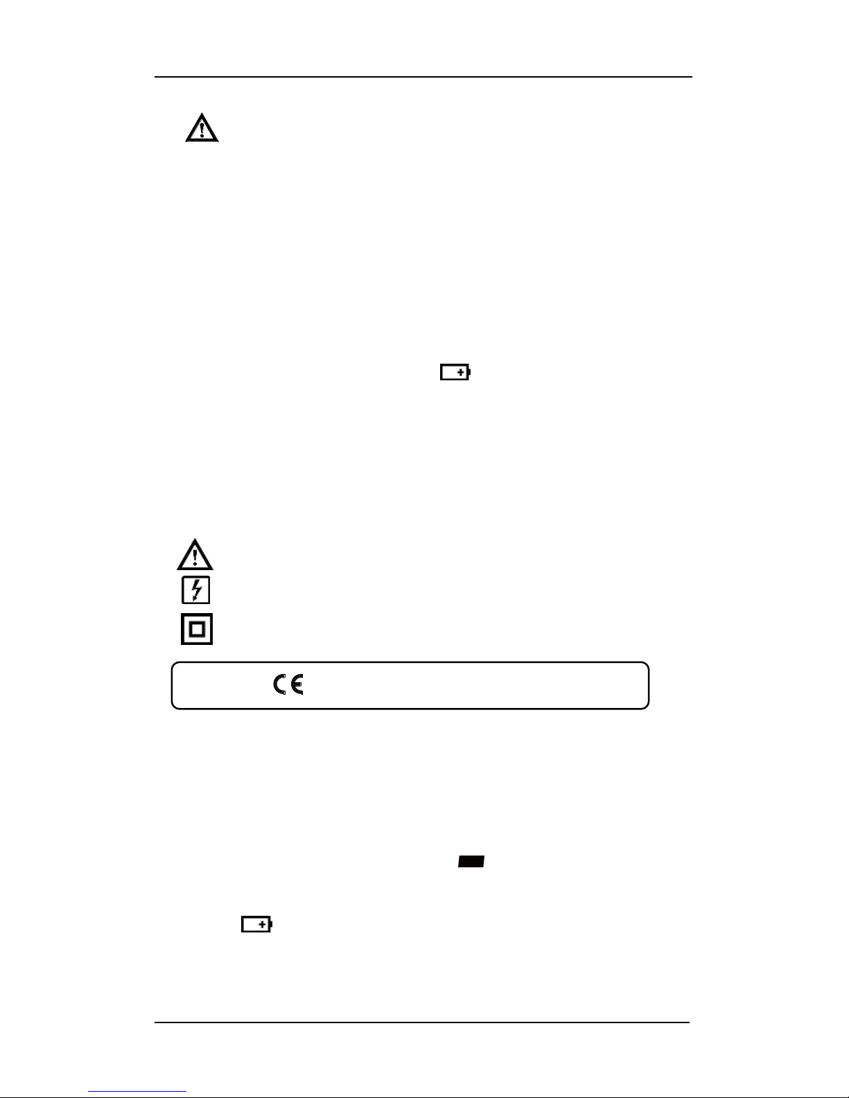
6. Change the battery when the symbol appears to avoid
incorrect data.
Environmental Conditions
Operation Temperature: 0°C to 40°C (32°F to 104°F); < 80 % RH
Storage Temperature: -10°C to 60°C (14°F to 140°F); < 80 % RH
Explanation of Symbols
Attention refer to operating instructions.
Dangerous voltage may be present at the terminals.
This instrument is double insulated.
Approvals: EN61010 300V CAT-IV
2. GENERAL SPECIFICATION
Digital Display:
4 digit liquid crystal (LCD), Maximum reading 6,000 counts.
Polarity:
When a negative signal is applied, the “ ” sign appears.
Low Battery Indication:
When the battery voltage is below that required for proper operation
then the symbol will appear on the LCD display.
Sample Rate:
2 times/sec for digital data.
Center 265 True RMS Leakage Current Clamp Meter
3
Power Source:
1.5V size AAA battery X 2
Typical battery Life: (without buzzer, backlight)
40 hours at AC mA and ACA and ACV function;
60 hours at DCV and Ohm function. (Alkaline battery)
Auto Power Off:
If there is no key or dial operation for 30 minutes, the meter will power
itself off to save battery life. This function can be disabled by pressing
and holding the “ HOLD ” button and powering on the unit.
Overload Indication:
When the applied signal is larger than the maximum for the range in
use the display will show .
Maximum Jaw Opening:
23 mm
Dimensions:
206 x 76 x 33.5 mm
Weight:
262g (with battery)
Accessories:
Carrying case, Batteries, Test Leads & Instruction Manual.
3. ELECTRICAL SPECIFICATION
The accuracy specification is defined as ± ( percentage of reading +
number of counts ) At 23±5°C, ≦80 %RH.
3-1 ACmA (True RMS)
Range
Resolution
Accuracy
50~60 Hz
50~500 Hz
6.000 mA
0.001 mA
1.0% + 8 counts
2.0% + 8 counts
60.00 mA
0.01 mA
1.0% + 5 counts
2.0% + 5 counts
600.0 mA
0.1 mA
Zero correction: Fractions smaller than approximately 0.006 mA are
calibrated to zero.
Low Pass Filter
Range
Resolution
Accuracy
6.000 mA
0.00 1mA
2.0% + 8 counts
60.00 mA
0.01 mA
2.0% + 5 counts
600.0 mA
0.1 mA
 Loading...