

Center 262 Instruction Manual
MILLIAMP CLAMP METER
262

262-01 SEP. 2014

TABLE OF CONTENTS
1.
SAFETY INFORMATION ....................................................... 1
2.
GENERAL SPECIFICATION................................................. 1
3.
ELECTRICAL SPECIFICATION ........................................... 2
3-1
Direct Voltage ........................................................................ 2
3-2
Alternating Voltage ................................................................ 2
3-3
Direct Current ........................................................................ 2
3-4
Alternating Current ................................................................ 3
3-5
Resistance(Ω) ....................................................................... 3
3-6
Continuity( ) ........................................................................ 3
4.
DESCRIPTION OF THE INSTRUMENT ............................. 4
4-1
Description of the display ...................................................... 4
4-2
Description of front and rear .................................................. 5
5.
BUTTON INSTRUCTION ....................................................... 6
5-1
HOLD Function ...................................................................... 6
5-2
MAX/MIN Function ................................................................. 6
5-3
ZERO Function ...................................................................... 6
5-4
BACKLIGHT Function ........................................................... 6
6. MEASURING INSTRUCTION ............................................... 7
6-1
ACA Measurement ................................................................ 7
6-2
DCA Measurement ................................................................ 8
6-3
ACV Measurement ................................................................ 8
6-4
DCV Measurement ................................................................ 9
6-5
Continuity Measurement ........................................................ 9
6-6
Resistance Measurement .................................................... 10
7.
BATTERY CHANGING ........................................................ 10
8.
MAINTENANCE ..................................................................... 11
Clamp Meter
1
1. SAFETY INFORMATION
Do not operate the tester if the body of meter or the test lead look
broken.
Check the main function dial and make sure it is at the correct position
before each measurement.
Do not perform resistance and continuity test on a live power system.
Do not apply voltage between the test terminals and test terminal to
ground that exceed the maximum limit record in this manual.
Keep the fingers after the protection ring when measuring through the
test lead.
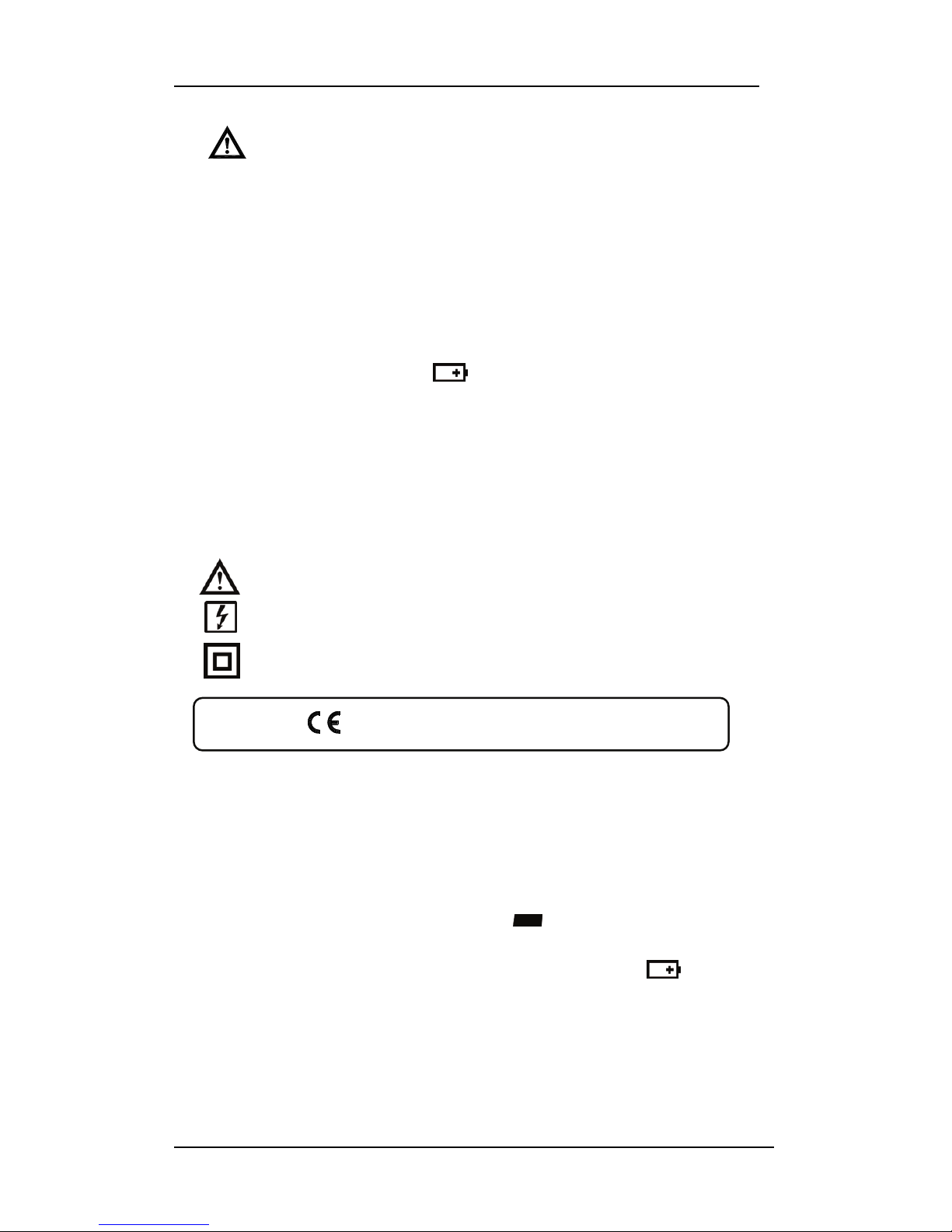
Chang the battery when the
symbol appears to avoid incorrect
data.
Environmental Conditions
Operation Temperature: 0°C to 40°C(32°F to 104°F); < 80 % RH
Storage Temperature: -10°C to 60°C(14°F to 140°F); < 80 % RH
Explanation Symbols
Attention refer to operation Instructions.
Dangerous voltage may be present at terminals.
This instrument has double insulation.
Approvals:
EN61010 300V CAT IV
2. GENERAL SPECIFICATION
Digital Display:
4 digital liquid crystal(LCD), Maximum reading 5000.
Polarity:
When a negative signal is applied, the
signal appears.
Low Battery Indication:
When the battery is under the proper operation range,
will appear
on the LCD display.
Sample Rate:
2 times/sec for digital data.
Clamp Meter
2
Power Source:
1.5V size AAA battery X 2
Typical battery Life: (without buzzer, backlight)
Type:
30 hours at DCA function;
60 hours at ACA and ACV function;
100 hours at DCV and Ohm function.
Auto Power Off:
If there is no key or dial operation for 30 minutes, the meter will power
itself off to save battery consumption. This function can be disabled by
press and hold the “ HOLD ” button then power the unit on
Over Load:
When the signal larger than the maximum will be show
.
Maximum jaw opening:
23 mm
Dimensions:
206 x 76 x 33.5 mm
Weight:
262g (with battery)
Accessories:
Carrying case, Batteries, Test Lead & Instruction Manual.
3. ELECTRICAL SPECIFICATION
The accuracy specification is defined as ± ( percent of reading + digit )
At 23±5°C,
≦80 %RH.
3-1 Direct Voltage
Range Resolution Accuracy
50V / 300V 0.01V / 0.1V 1.0% + 2dgts
Input impedance: 1 M
3-2 Alternating Voltage (True RMS)
Range Resolution Accuracy(40~1KHz)
50V / 300V 0.01V / 0.1V
1.2% ± 5dgts
Input impedance: 1 M
3-3 Direct Current
Range Resolution Accuracy
300.0mA 0.1mA
1.0% + 10dgts
3.000A 0.001A
10.00A 0.01A 3.0% + 10dgts
Influence of terrestrial magnetism: Less than ±1.0mA
Influence of CT opening and closing: Less than ±1.0mA
 Loading...