

Center 201 Instruction Manual
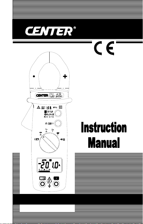
201
MINI AC/DC CLAMP
METER

CONTENTS
TITLE PAGE
I. Safety Information …………………………… 1
Environmental Conditions…………………………….
Explanation of Symbols……………….……………….
II. Specification………………………………………. 2
General Specification……………………………………
Electrical Specification………………………………….
III. Instrument Familiarization……………... 4
Symbol Definition………………………………………...4
Button instruction………………………………………..
IV. Measuring Instruction……………...……... 6
4.1 AC Current Measurement………………………...………
4.2 DC Current Measurement……………………………...…
4.3 AC Voltage Measurement……………………………...…
4.4 DC Voltage Measurement………………………………....9
4.5 Resistance Measurement………………………………..
4.6 Continuity Test……………………………………………
V. Battery Changing……………………………..12
.. 1
.. 1
2
3
5
.. 6
.. 7
.. 8
10
…..11
VI. Maintenance………………………………………13
I. Safety Infor mation
Do not operate the tester if the body of meter or the test
lead look broken.
Check the main function dial and make sure it is at the
correct position before each measurement.
Do not perform resistance and continuity test on a live
power system.
Do not apply voltage between the test terminals and test
terminal to ground that exceed the maximum limit record in
this manual.
Exercise extreme caution when measuring live system with
voltage greater than 60V DC or 30V AC.
Keep the fingers after the protection ring when measuring
through the test lead.
Change the battery when the symbol appears to avoid
incorrect data.
Environmental Conditions:
Altitude up to 2000 meters.
Operating temperature:
Storage temperature: Pollution Degree: 2
Installation Categories II
Explanation of Symbols:
Attention! Refer to operation Instructions.
Dangerous voltage may be present at terminals.
This instrument has double insulation.
Approvals: EN61010 600V CAT II 300V CAT III
0°C ~ 40°C, <80% RH, non-condensing
10°C ~ 60°C, <70% RH, battery removed
1
II. Specification
General Specification:
Digital Display:
3 3/4 digits LCD display with maximum reading 3999
Analog Display:
42 segments fast analog bar display
Symbol and Scale range:
Adjust automatically according range and input signal
Polarity:
When negative signal in apply to the tester,
Over Load:
When the signal larger than the maximum will be show
Sample Rate:
2 times/sec for digital data
20 times/sec for analog bar
Low Power Indication:
When the battery is under the proper operation range,
will appear on the LCD display.
Power Source: UM-4 or AAA 1.5V battery x 2.
Power life: Approx. 50hr (Alkaline Battery )
Auto Power Off:
If there is no key or dial operation for 30 minutes, the meter
will power itself off to save battery consumption. This
function can be disabled by press and hold the ZERO
button then power the unit on.
Clamp opening size: 30mm
Dimension (L x W x H) :
193 x 50 x 28mm, 7.60 x 1.97 x1.1 inch
Weight: 240g, 8.46
Accessory:
Instruction Manual, Leather Case, Test lead, Battery 1.5Vx2
OZ ( include battery)
2
will show.

Electrical Specification:
±
The accuracy specification is defined as
( …%reading+…count )
At 23±5℃, ≦80 %RH
DCV (Autorange)
Range Resolution Accuracy Input Impedance Overload Protection
400V 0.1V
600V 1V
1%+2 10M
Ω
660Vrms
ACV (Autorange)
Accuracy
Range Resolution
400V 0.1V
600V 1V
50Hz~500Hz
1.5%+5 10M
Input Impedance Overload Protection
Ω
660Vrms
DCA (Autorange)
Range Resolution
40A 0.01A
400A 0.1A
Accuracy
Overload Protection
2.5%+10 600Arms
ACA (Autorange)
Range Resolution Accuracy Band Width Overload Protect i o n
40A 0.01A
400A 0.1A
2%+10 50Hz~500Hz 600Arms
Ohm ( Ω )
Range Resolution Accuracy Max. Test Voltage Overload Protection
400Ω 0.1Ω 1%+2 1.5VDC 600Vrms
Continuity ()
Range Active Region Max. Test Voltage Overload Protection
< 40 Ohm
1.5 VDC 600Vrms
3
 Loading...