

Page 1

CONTENTS
TITLE
PAGE
SAFETY INFORMATION……..……………...….1
FEATURES………………………………..……....2
1.SPECIFICATIONS………………………..…….2
1-1 General information…………………...…2
1-2 Electrical Specifications……………. ..…5
2.PART S & CONTROLS……….………….…….8
2-1 Name of Parts and Positions…. ……….8
2-2 Operating Instruction…………………..
11
2-2-1 Scale Ranging…….………………. ..
11
2-2-2 DC Voltage Measurement..……..…..
11
2-2-3 AC Volt age Measurement..……..…..12
2-2-4 AC/DC Current Measurement..….…
13
2-2-5 Diode Test..…………………………..
14
2-2-6 Resistance Measurement…..……… 15
2-2-7 Continuity Measurement..…………..
15
2-2-8 Frequency Measurement..……… ....16
3.BATTER Y & FUSE REPLACEMENT……… 17
3-1 Battery Check & Replacement………...
17
3-2 FUSE Replacement………………...…..
17
4.MAINTENANCE……..…..…………………… 19
Page 2
1
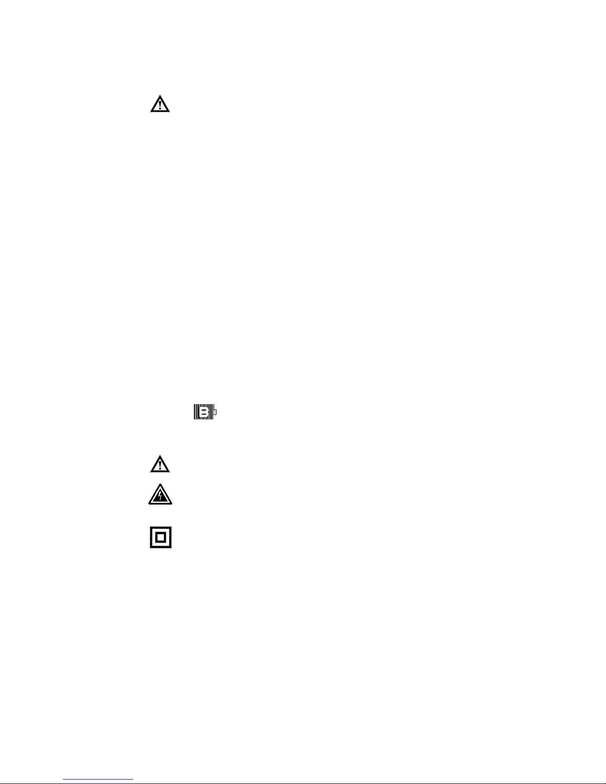
Read First: Safety Information
․ Never use the meter if the meter or test leads look
damaged.
․ Be sure the test leads and switch are in the correct
position for the desired measu rement.
․ Never measure resistance or testing acoustic continuity
in a circuit when power is applied.
․ Never connect the probe to a voltage source when the
test leads are plugged into the 10 A input jack .
․ Never connect the probe to a voltage source when the
function are in
u
A or mA range.
․ Never apply more than rated voltage between any input
jack and earth ground.
․ Be careful when working with voltages above 60 V dc or
30 V ac rms. Such voltages pose a shock hazard.
․ Keep your fingers behind the finger guards on the test
probes when making measurements.
․ To avoid false readings, replace the battery immediately,
When symbol appears.
Symbols:
ReadSafetyInformationFirst
DangerousVoltageMayBePresent
Meterisprotectedthroughoutbydoubleinsulationor
reinforcedinsulation.
When servicing, use only specified replacement parts.
1. SPECIFICATIONS
1-1 General information
Page 3
2
Display:
Digital: 4000 counts
Analog: 42 segments
Maintenance & Clearing:
Repairs or servicing not covered in this manual should only by
qualified personal.
Periodically wipe the case with a dry cloth and detergent . Do not
use abrasives or solvents on this instruments.
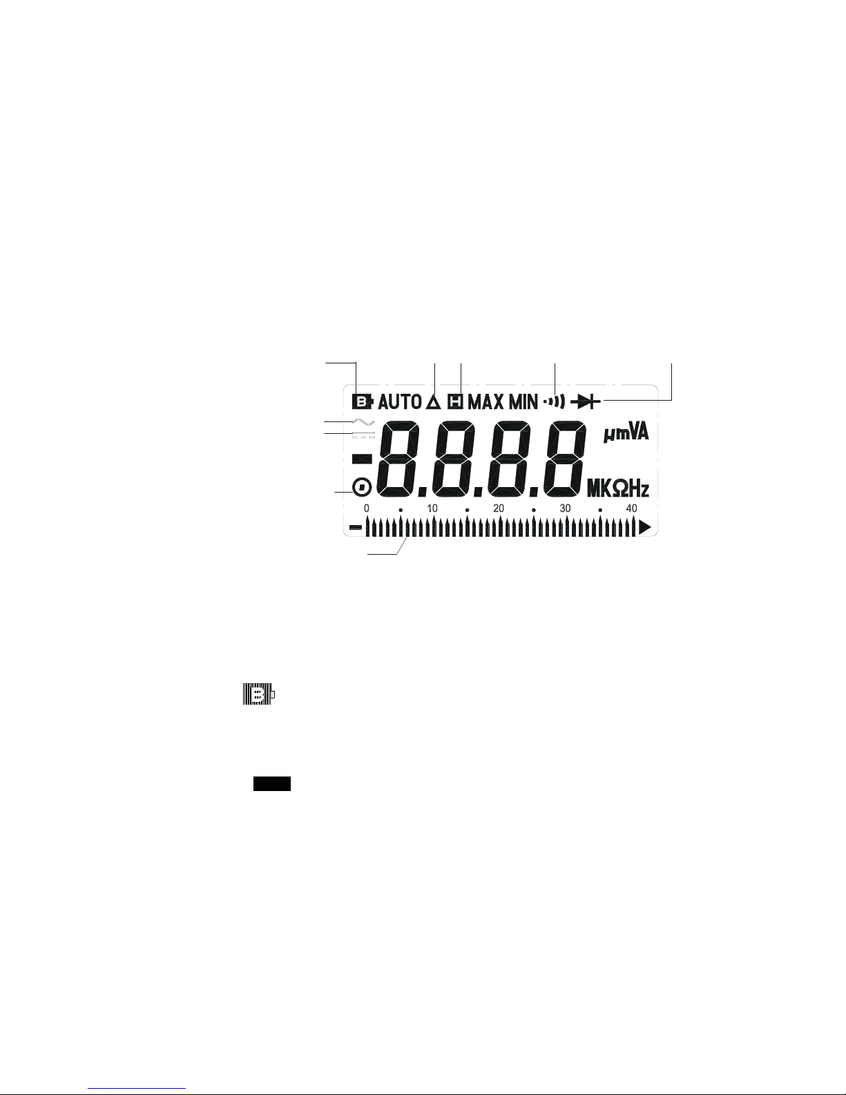
Display Symbol Definition:
Sampling Rate:
Digital: 2 times/sec
Analog: 20times/sec for Bargraph indication.
Over Range Indication: LCD will show “OL”.`
Low Battery Indication:
The is displ aye d when the battery voltage drop below the
proper operating range.
Battery type: 1.5V.SIZE AAA Batter
Battery Li fe: 500hrs typical (alkaline Battery)
Polarity: ”
” Indicates negative input.
Auto Power Off Time: 30 minutes
Operating Temperature and Humidity:
0℃to 40℃(32℉to 104℉) below80%RH
Storage Temperature and Humidity:
-10℃to 60℃(14℉to 140℉) below70%RH
Low Battery Relative Reading Data Hold Continuity Beeper
Diode
AC Symbol
Manual Range
Bargraph Indication
DC Symbol
Page 4
3
Weight: Approx.220g(7.76oz)
Dimensions(L×W×H):
150mm×72mm×35mm (5.9”×2.83”×1.38” )
Accessories:
Test leads, Spare fuse ( 0.5A/250V ),Batteries and Instruction manual.
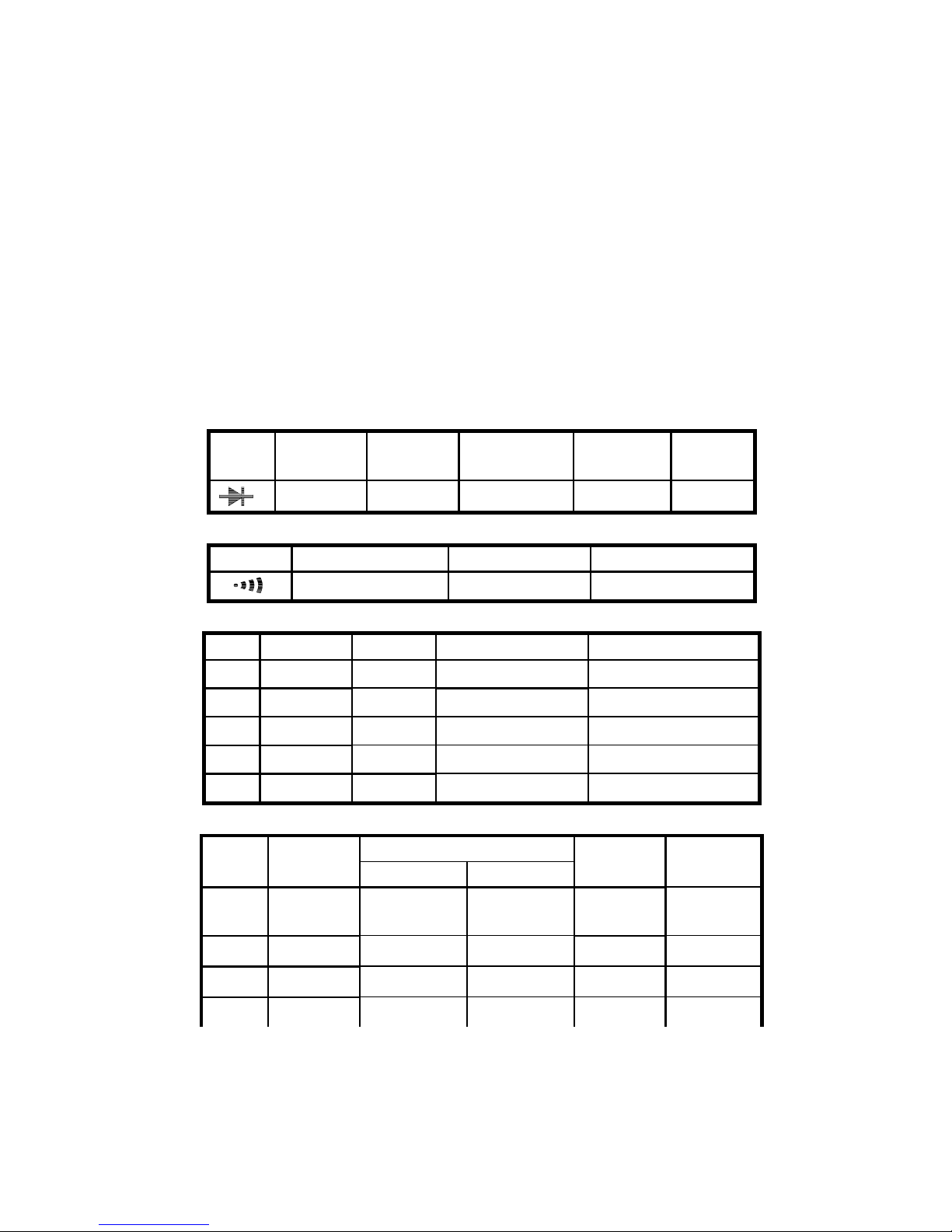
1-2 Electrical Specifications
Accurace specificatio n:±([… %of reading]+ […number of least significant
digits]) at 18℃to 28℃( 64℉to 82℉)≦80%RH
Diode Tester
Range Resolution Accuracy Test Current Test Voltage
Overload
protection
1mV 1%+ 2 <1mA <3.2V 600Vrms
Continuity beeper
Range Active Range Test Voltage Overload protection
under40
Ω
<1.5V 600Vrms
DC Voltage ( Auto Range)
Range Resolution Accuracy Input Impedance Overload Protection
400mV 0.1mV 0.5%+2
≒
200 MΩ
750Vrms
4V 1mV 0.5%+2
11M
Ω
750Vrms
40V 10mV 0.5%+2
10M
Ω
750Vrms
400V 100mV 0.5%+2
10M
Ω
750Vrms
600V 1V 0.8%+2
10M
Ω
750Vrms
AC Voltage ( Auto Range)
Accuracy
Range Resolution
45Hz~400Hz 400Hz~1KHz
Input
Impedance
Overload
Protection
400mV 0.1mV
1%+5
(45Hz~100Hz)
≒
200 MΩ
750Vrms
4V
1mV 1%+4 1.5%+4
11M
Ω
750Vrms
40V 10mV 1%+4
1.2%+4
10M
Ω
750Vrms
400V 100mV 1%+4
1.2%+4
10M
Ω
750Vrms
Page 5
4
600V 1V 1%+4
1.2%+4
10M
Ω
750Vrms
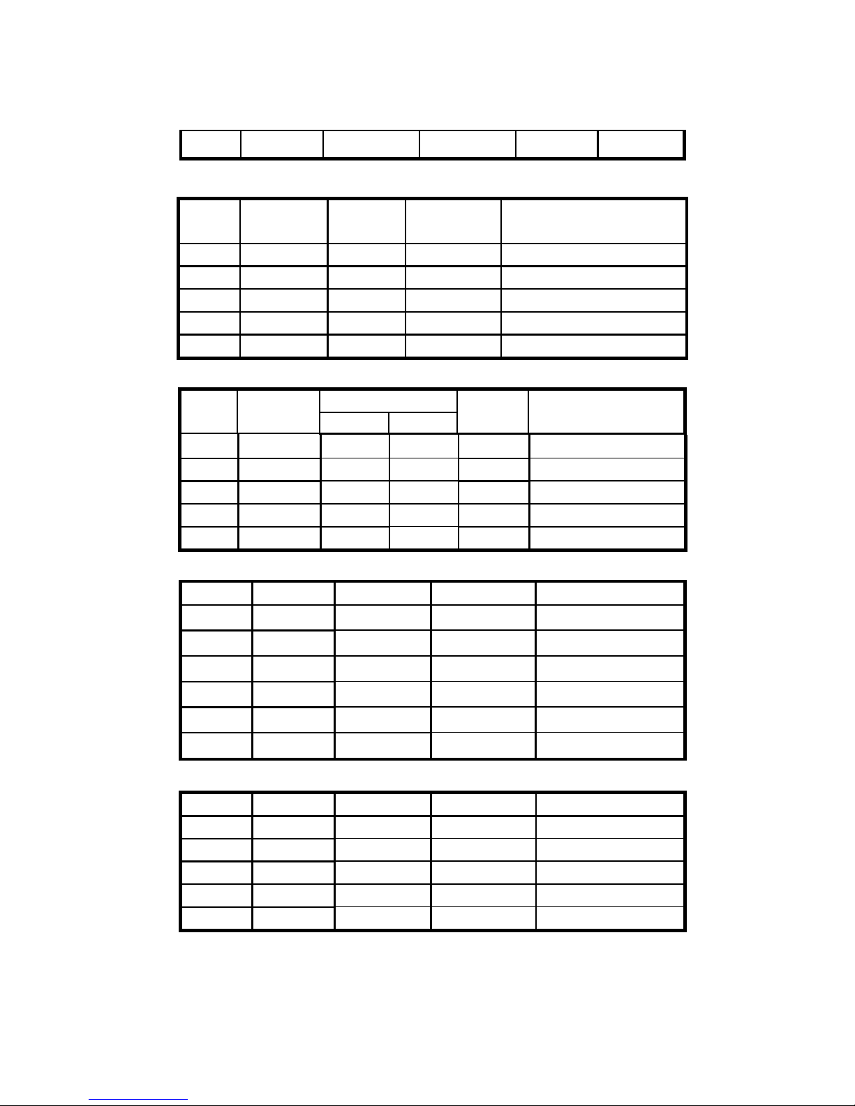
DC Current (uA,mA,Auto Range)
Range Resolution Accuracy
Burden
Voltage
Overload Protection
400uA 0.1uA 1%+2 <0.25V 0.5A / 250V Fast Blow Fuse
4000uA
1uA 1%+2 <1V 0.5A / 250V Fast Blow Fuse
40mA 10uA 1%+2 <0.25V 0.5A / 250V Fast Blow Fuse
400mA 100uA 1%+2 <1.5V 0.5A / 250V Fast Blow Fuse
10A 10mA 1.2%+2 0.35V
10A / 250V Fast Blow Fuse
AC Current(uA,mA,Auto Range)
Accuracy
Range Resolution
45Hz~500Hz 500Hz~1KHz
Burden
Voltage
Overload Protection
400uA 0.1uA 1.3%+5 1.6%+5
<0.25Vrms 0.5A / 250 Vfast Blow Fuse
4000uA 1uA 1.3%+5 1.6%+5
<1Vrms 0.5A / 250 VFast Blow Fuse
40mA 10uA 1.3%+5 1.6%+5
<0.25Vrms 0.5A / 250 VFast Blow Fuse
400mA 100uA 1.3%+5 1.6%+5
<1.5Vrms 0.5A / 250 VFast Blow F us e
10A 10mA 1.5%+5 1.8%+5
<0.35Vrms 10A / 250V Fast Blow F us e
Ohms ( Auto Range)
Range Resolution Accuracy Test Voltage Overload Protectio n
400Ω 0.1Ω
0.75%+2 <1.5VDC 600Vrms
4KΩ 1Ω
0.75%+2 <1.5VDC 600Vrms
40KΩ 10Ω
0.75%+2 <1.5VDC 600Vrms
400KΩ 100Ω
0.75%+2 <1.5VDC 600Vrms
4MΩ 1KΩ
0.75%+2 <1.5VDC 600Vrms
40MΩ 10KΩ
1.2%+3 <1.5VDC 600Vrms
Frequency ( Auto Range)
Range Resolution Accuracy Sensitivity Overload Protection
4 KHz 1Hz 0.1%+1 <300mVpp 600V rms
40KHz 10Hz 0.1%+1 <300mVpp 600V rms
400KHz 100Hz 0.1%+1 <300mVpp 600V rms
4MHz 1KHz 0.1%+1 <3Vpp 600V rms
40MHZ 10KHz 0.1%+1 <3Vpp 600V rms
Page 6
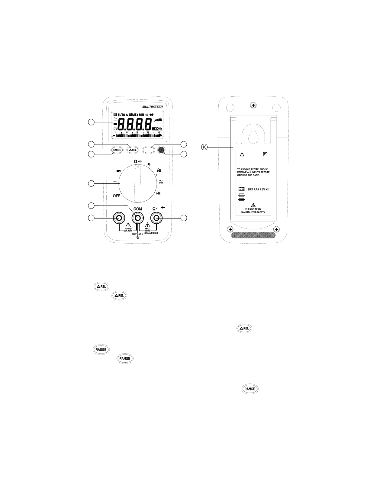
5
1
2
3
6
7
8
4
5
9
V
A
VA
uA
mAHz
MIN
MAX
V
Hz
mA
uA
IEC 1010
POLLUTION DEGREE 2
F 0.5A 250V
F 10A 250V
WARNING
600V CAT II
2.PARTS & CONTROLS
2-1 Name of Parts and Position:
← LCD Display :
Measured values, unit, function and decimal points symbols are
displayed.
↑ Relative Button:
Press button to enter the relative mode . The Disp lay i s zeroe d ,
and the reading is stored as reference value for subsequent
measurements. Press it again, the “△” annunciator blinking and stored
relative value will d isplay . Press and hold down button for 1
second to exit the relative mode.
→ Auto-range & Manual Range Button:
․ Press to select the Manual Range mode and the ⊙
annunciator turn on and The meter remains in the same range it
was .
․In the Manual Range mode, each time you press button , the
range ( and the input range annunciate ) increases , and a new
Page 7
6
value is displayed.
․If the meter is in the highest range, the next range is change to the
lowest range. To exit the Manual Range mode and return to Auto
Range mode, Press and hold down for 1 seconds, the
AUTO annunciate turns back on.
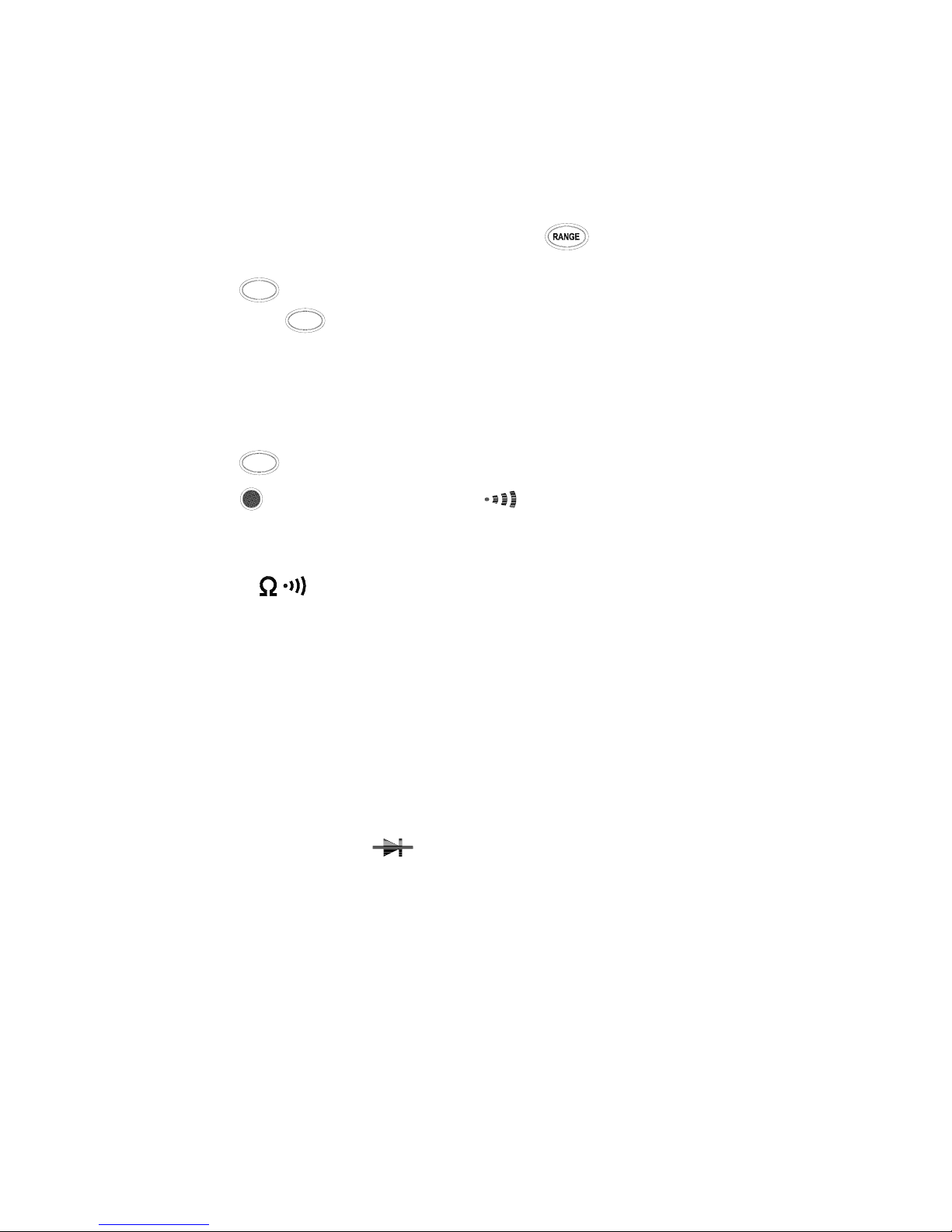
↓ MAX/MIN recording button:
Press button to enter the maximum and minimum recording
mode, select the proper range before using MAX/MIN to ensure that
reading value will not exceed the measurement range. Press the
button once to select MAX value.
Press it again to select MIN value, and press again to select current
value with ” MAX.MIN ” annunciator blinking. Press and hold down
button for 1 second to exit the MAX MIN mode.
° AC/DC Current Select and
/
Ω Select Button:
․To select function AC or DC in current Ampere range.
․To select continuity measurements or Resistance measurement at
range.
± Function Selector Switch:
For power OFF and sel e ction of desired Function Range.
″ COM Measuring Connector:
To connect negative lead (black test lead ) for voltage, frequency,
current, resistance, diode and continuity measurement.
≥ 10A Measuring Connector:
To connect positive lead (red test lead)for current measurement below
10A.
× VΩ,μA, mA, Hz,
Measuring Connector:
To connect positive lead ( red test lead ) for voltage, diode, frequency,
micro ampere, milliampere and continuity measurement.
Note:
To avoid blowing an input fuse, use the 10 A jack until you
are sure that the current is less than 400mA. When Doing
Current Measurement.
MAX
MIN
MAX
MIN
MAX
MIN
Page 8
7
∝ Tilt stand
2-2 Operating Instruction
2-2-1 Ranging
The meter defaults to autorange mode when you turn on the Meter.
Manual ranging is available in V~, V , ohms , A~ , A ,
frequency.
To return to a utorange, press for 1 second or turn the rotary
switch.
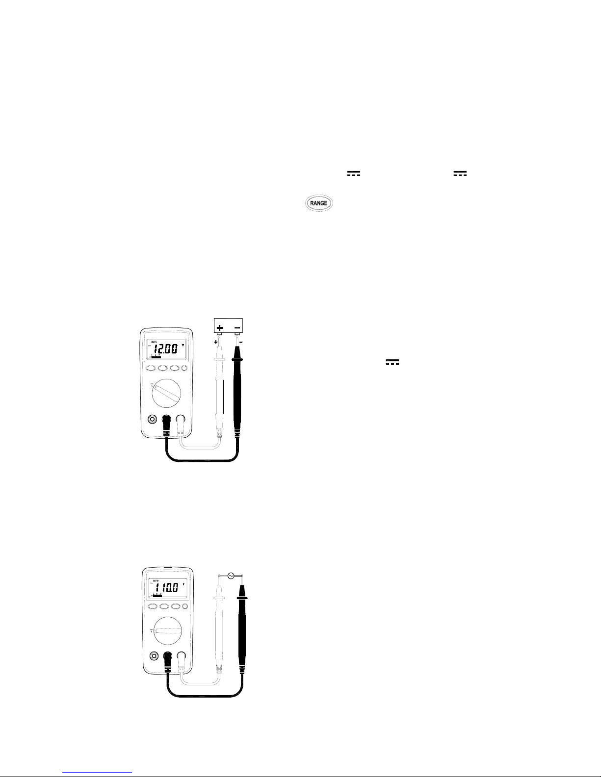
2-2-2 DC Voltage Measurements
WARNING!
Maximum Input Voltage is 1000V DC, 750V AC. Do not attempt
to Take any voltage measurement that may exceed toavoid
Electrical shock hazard and/or damage to this instrument
⊇ Connect red test lead to “ V ” jack and
black test lead to “ COM ” jack.
⊄ Set Range Switch to V range.
⊂ Connect the test leads IN PARALLEL to
the circuit being measured.
⊆ Read the Voltage value on LCD.
2-2-3 AC Voltage Measurements
WARNING!
Maximum Input Voltage is 1000V DC, 750V AC. Do not attempt
to Take any voltage measurement that may exceed to avoid
Electrical shock hazard and/or damage to this instrument.
⊇ Connect red test lead to “ V ”jack and black
test lead to “COM ”jack.
⊄ Set Range Switch to V
~
range.
⊂ Connect the test leads IN PA RALLEL to the
circuit being measured.
⊆ Read the Voltage value on LCD.
Page 9
8
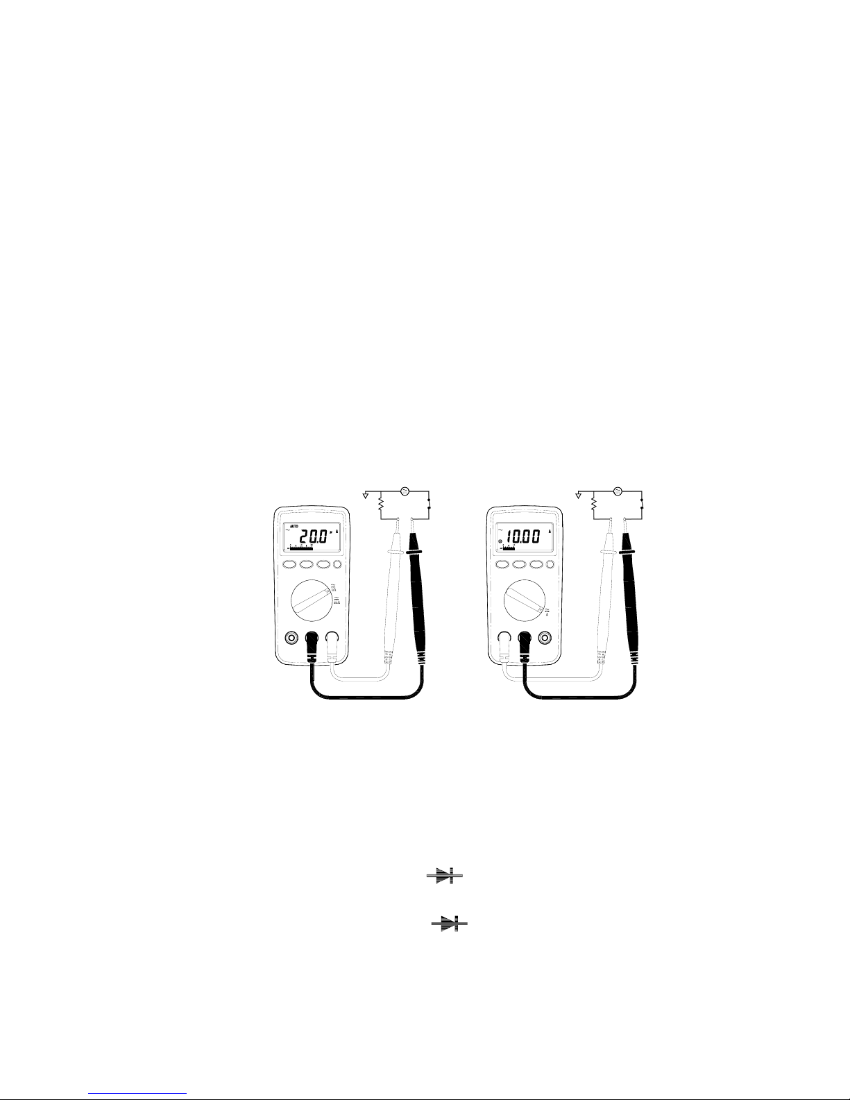
uA . mA measurement
Amp
measurement
2-2-4 AC/DC Current Measurements
WARNING!
To avoid injury, do not attempt a current measurement if the
open circuit voltage exceeds the rate voltage of the meter.
⊇ Connect red test lead to the “mA / uA ”jack for Current measurements
up to 400mA.( For measuring Current between 400mA to 10A ,
Connect red test lead to “ 10 A ” jack ) Connect black test lead
to“ C OM ” jack.
⊄ Set Range selector Switch to desired A range and press DC/AC
button to select AC/DC function.
⊂ Cut the power to the circuit to be tested and Connect the instrument
IN SERIES with the circuit with the black test lead on the negative
“ - ”side and the red lead on the positive “ + ”side being measured.
⊆ Apply power and read the ampere value on LCD.
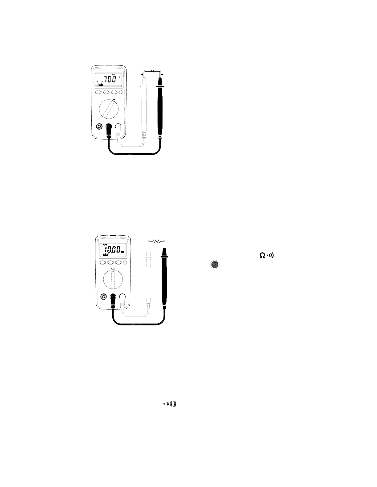
2-2-5 Diode Tests
WARNING!
Before taking any in-circuit measurement ,remove power from
the circuit being tested and discharge all capacitors in the
circuit.
⊇ Connect red test lead to “
”jack and black test lead to
“COM ” jack.
⊄ Set Range selector Switch to “
” range.
Page 10
9
⊂ Connect the red test lead to the anode
side and black test lead to the cathode
side of the diode being tested.
⊆ Read forward Voltage( V
f
) value on
LCD.
∈ If the polarity of test leads are reversed
with diode polarity ⊂, the digital reading
show “ OL ”.This can be used for
distinguishing anode and cathode
terminal of a diode.
2-2-6 Resistance Measurements
WARNING!
Before taking any in-ci rcuit measureme nt , remove power fr om
the circuit being tested and discharge all capacitors in the
circuit.
⊇ Connect red test lead to “ Ω ”jack and
black test lead to “COM ”jack.
⊄ Set Range Switch to “ ” range
and press button to “Ω”function.
⊂ Connect test lead to the circuit being
measured and read the resistance value
on LCD.
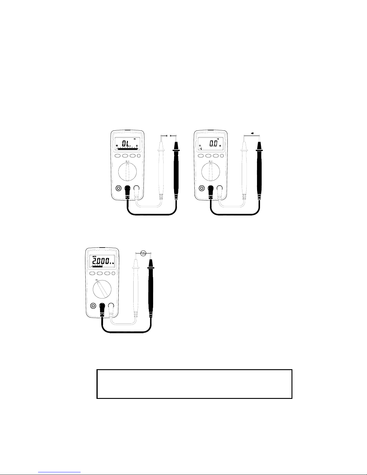
2-2-7 Continuity Measurements
WARNING!
Before taking any in-circuit measurement ,remove power from
the circuit being tested and discharge all capacitors in the
circuit.
⊇ Connect red test lead to “Ω”jack and black test l ead to “COM ” jack .
⊄ Set Range Switch to “
” range , by pressing button.
Page 11
10
⊂ Remove power from the circuit being tested and discharge all
capacitors.
⊆ Connect test lead to the circuit being measured.
∈ When the impedance between the test jack is lower tha n 4 0Ω,it will
activate a continuous beeper ( 2KHz).
Note: Continuity Test is available to check open/short of the circuit .
Open circuit Short circuit
2-2-8 Frequency Measurements
⊇ Connect red test lead to “Hz” jack and
black test lead to “COM ”jack.
⊄ Set Range Switch to “Hz” range .
⊂ Connect the test lead IN PARALLEL to the
circuit being measured.
⊆ Read the frequency value on LCD.
3.BATTERY & FUSE REPLACEMENT
WARNING!
To prevent electrical hazard or shock , turn off multimeter
and disconnect test leads before removing back cover.
Page 12
11
3-1 Battery Check & Replacement
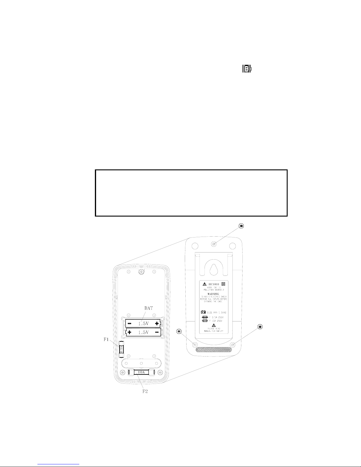
1. As battery power is not sufficient, LCD will display “ ”.
Replacement of two new batteries type AAA 1.5V is Required.
2. Set Range Switch to “ OFF ” position .Use a screwdriver to re move the
rear cover. Ta ke out the battery and replace them with two new batteries
of type AAA1.5V.
3. Place back the rear cover and secure it with the original screw.
3-2 FUSE Replacement
1. Set Range Switch to “ OFF ” position. Use a screwdrive to remove
the rear cover. Take out the malfunction fuse and replace it with a
new fuse rated 0.5A / 250A ( or 10A / 250V ) of fast blow type.
2. Place back the rear cover and secure it with the original screw.
WARNING!
For safety , use exact replacement .
Fuse 1 : F0.5A / 250V 5
∮
×20 mm Fast blow type
Fuse 2 : F10A / 250V 6.3
∮
×32 mm Fast blow type
screw
0.5Afuse
10Afuse
screw
Page 13

12
4.MAINTENANCE
WARNING!
To avoid electric shock, remove the test leads before
opening the case, and close the case before using the
meter.
To prevent fire and possible arc-flash, use fuses with
ratings shown on the back of the meter.
Caution!
To avoid contamination or static damage, do not touch
the circuit board without proper static protection.
 Loading...