

Page 1
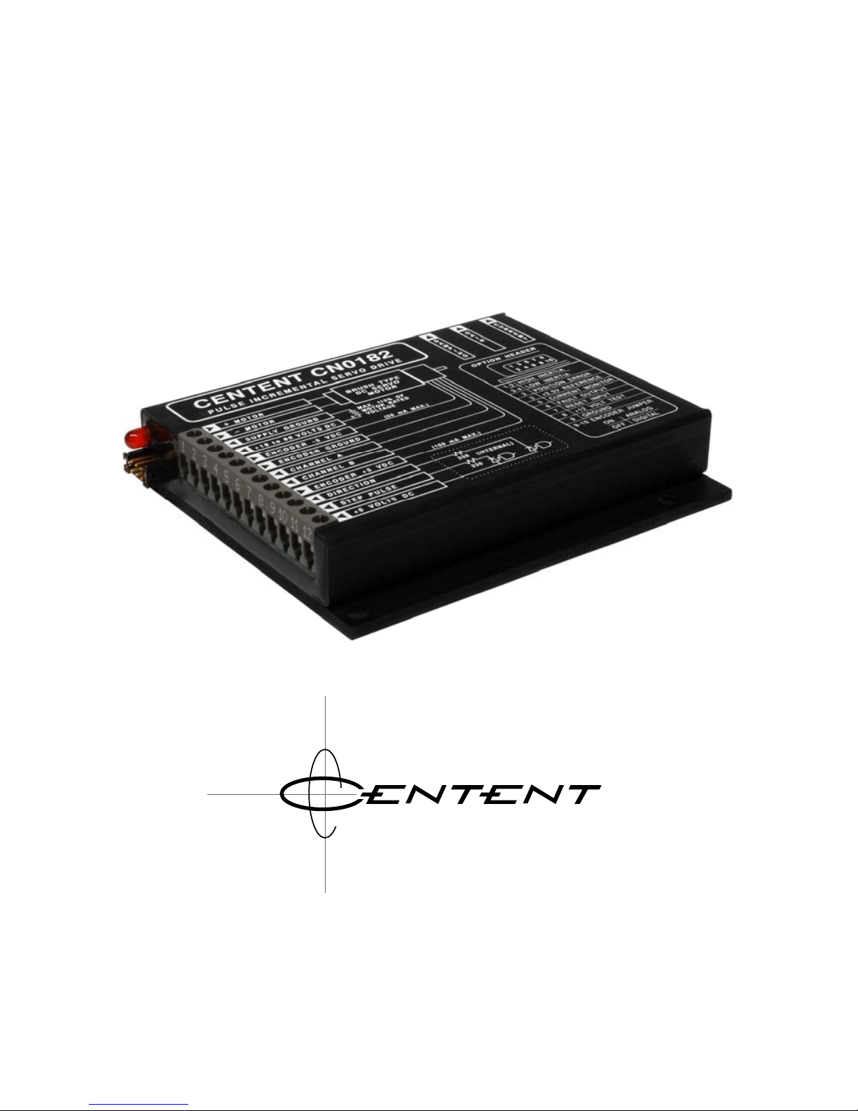
OPERATING MANUAL
CN0182 SERVO DRIVE
3879 SOUTH MAIN STREET 714-979-6491
SANTAANA, CALIFORNIA 92707-5710 U.S.A.
0 M P A N Y
Page 2

CN0182 PULSE INCREMENTAL SERVO DRIVE
This manual contains information for installing and operating the following
Centent Company product:
CN0182 Servo Drive
Centent and the Centent Company logo are trademarks of Centent Company.
Other trademarks, tradenames, and service marks owned or registered by any
other company and used in this manual are the property of their respective
companies.
Copyright © 2019 Centent Company
3879 South Main Street
Santa Ana, CA 97207
All Rights Reserved
ii
Page 3

CENTENT COMPANY
iii
CONTENTS
GENERAL DESCRIPTION ...................................................................................1
LOCATION OF COMPONENTS.......................................................................... 2
GETTING STARTED.............................................................................................. 3
QUICK SETUP........................................................................................................ 3
THEORY OF OPERATION...................................................................................4
Main Elements..................................................................................................... 4
Auxiliary Elements .............................................................................................. 5
Current Limit........................................................................................................ 7
Protection Circuits............................................................................................... 8
TERMINAL BLOCK FUNCTIONS
Motor Group....................................................................................................... 10
Power Supply Group ........................................................................................ 11
Encoder Group.................................................................................................. 12
Sine-Cosine Encoders................................................................................................14
TTL Encoders ..............................................................................................................14
Command Group............................................................................................... 15
OPTION HEADER................................................................................................17
System Inertia.................................................................................................... 17
Position Error..................................................................................................... 18
+2.5V Reference...............................................................................................18
Current Monitor ................................................................................................. 18
Fault Output....................................................................................................... 19
Reset Input......................................................................................................... 20
+12 Volt Test...................................................................................................... 20
Encoder Jumper................................................................................................ 20
Ground................................................................................................................ 20
TUNING THE CN0182 SERVO DRIVE
Current Trimpot................................................................................................. 21
Gain Trimpot...................................................................................................... 22
Damping Trimpot............................................................................................... 22
Integral Coefficient............................................................................................ 23
Servo Loop Tuning ........................................................................................... 23
Interpreting Figure 12 – Optimum Damping.................................................. 27
Picking A Motor................................................................................................. 27
Motor Fundamentals......................................................................................... 28
SPECIFICATIONS................................................................................................31
FULL SCALE DRAWING.................................................................................... 32
Page 4

Page 5

GENERAL DESCRIPTION
The CN0182 is a closed-loop PID (proportional-integral-differential) positioning servo drive
that provides closed-loop control of brush-type DC servo motors. The power amplifier is an
‘H’ bridge utilizing MOSFET technology. The drive is capable of delivering up to 20 amps
of continuous current to the motor. Motion instructions are sent to the CN0182 as Step and
Direction in a pulse train format.
The CN0182 operates on a single voltage DC power supply ranging between 18 and 80 volts
DC. The power supply voltage is determined by the motor’s rated voltage. The power supply
may be regulated or unregulated.
The motor driven by the CN0182 must be equipped with an incremental encoder with either
a digital (TTL) or analog (sine-cosine) output. Analog encoders with
±1 volt outputs can be
connected directly to the CN0182. Analog encoders that do not comply with this voltage
specification may be used but will require external amplification or attenuation to interface to
the CN0182.
The CN0182 also facilitates step motor to servo motor conversions since it is controlled by a
step motor indexer, pulse generator or motion controller, like a step motor drive. The servo
motor exhibits holding torque, velocity, tracking, incremental motion and no minimum
operating speed, while retaining the advantages of a DC servo motor such as increased high
speed torque, absence of vibration and low heating. The upgrade from stepper to servo
retains the existing indexer and control software while providing all the advantages of a
closed loop servo motor system.
Torque and loop stability are controlled by trimpots built into the drive. A screwdriver is
used to set motor current and tune the servo response of the drive.
Over-temperature and under-voltage protection is also built in. Upon sensing either of these
fault conditions, the CN0182 removes power from the motor, guarding both the drive and the
motor from damage. A light emitting diode (LED) provides visual indication of the fault
condition.
The CN0182 is compact, measuring 4.75" x 4" x 0.85" (121mm x 102mm x 22mm). It comes
encapsulated in a heat conductive epoxy and encased in an anodized aluminum cover. This
results in an environmentally rugged package that resists abuse and contamination.
Page 6
CN0182 PULSE INCREMENTAL SERVO DRIVE
LOCATION OF COMPONENTS
1
3
2
4
7
6
8
9
5
Figure 1
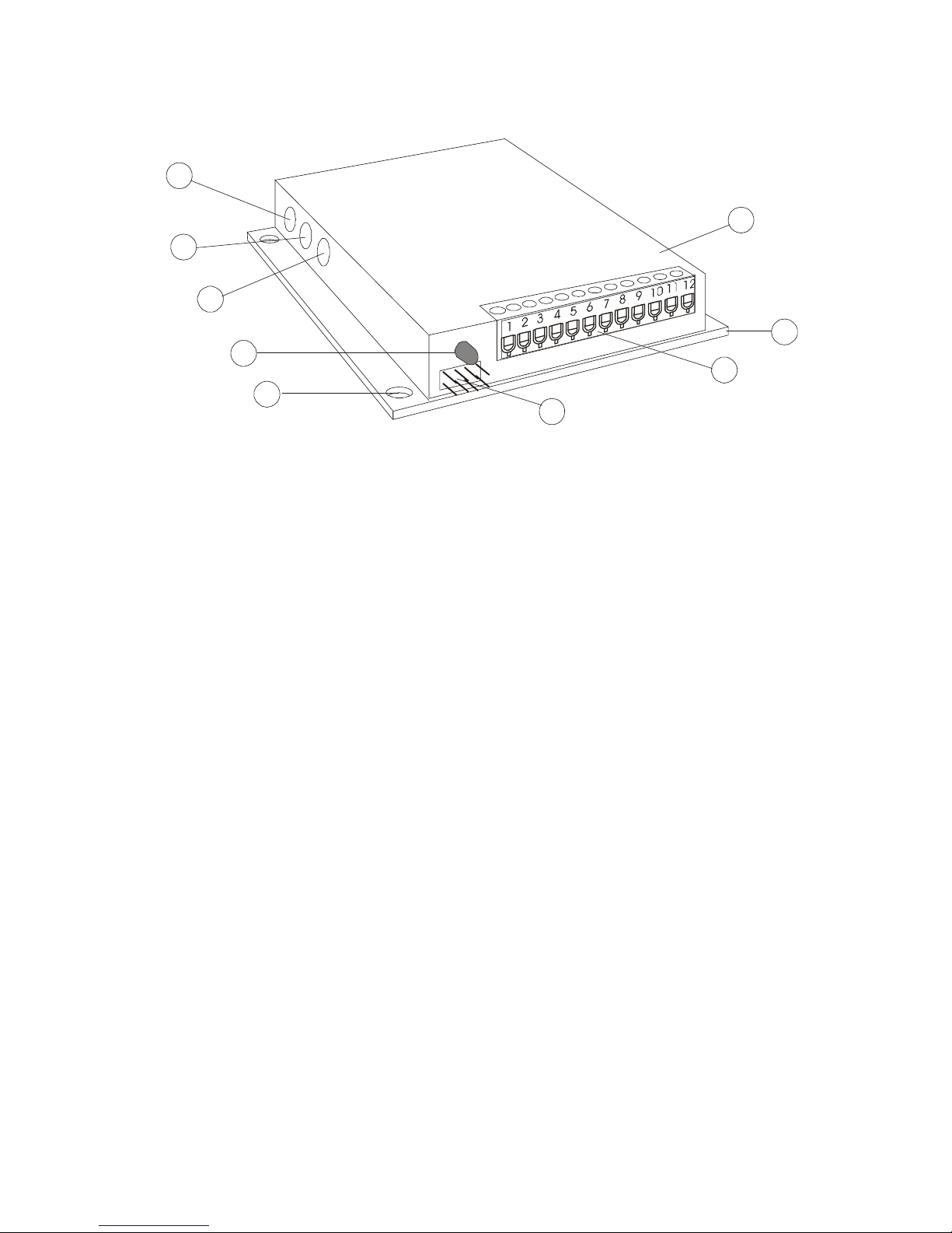
(1) MODULE
The CN0182 is encapsulated in epoxy and encased in an anodized aluminum cover.
Information is printed on the cover for the configuration of the Option Header and for the
electrical connections to the drive.
(2) MOUNTING PLATE (5)
MOUNTING HOLES
The temperature of the drive must never be allowed to exceed 70° C (158° F). The Centent
HSK heat sink kit may be ordered if additional heat sinking is required. Four mounting holes
on 3.625” centers are provided to secure the drive to the heat sink or user equipment.
(3) TERMINAL BLOCK
A 12 position terminal block provides direct electrical connections to the drive; just strip the
wire, insert and tighten the screw. The motor, power supply, encoder and indexer interface
are accessed through this connector. The function of each terminal is printed on the cover
adjacent to the screw. Do not over-tighten the screws, a torque-limit driver is recommended.
(4) OPTION HEADER
The user must configure this header for encoder type and system inertia. Position Error, Fault
output and Reset input functions are also available. Header pin assignments are printed on
the cover of the drive.
(6) FAULT LED
The LED (light emitting diode) is a visual indicator of the Fault Output. The LED is on when
the Fault Output pin on the Option Header is active.
(7) DAMPING TRIMPOT (8) GAIN TRIMPOT (9) CURRENT TRIMPOT
These built-in trimpots are for setting motor current and tuning the servo response of the
drive. Use a small screwdriver to turn the trimpots. Do not over-torque the trimpots.
2
Page 7

CENTENT COMPANY
GETTING STARTED
Five things are needed to construct a complete closed-loop servo drive system:
1. CN0182 Drive
2. Permanent magnet brush-type DC servo motor
3. Dual channel encoder (TTL or sine-cosine type)
4. DC power supply
5. Step and Direction pulse source (Indexer)
QUICK SETUP
The following steps will ensure a successful installation:
• Choose a motor adequate in size for the application
• Mount the desired encoder to the motor
• Choose a power supply with a voltage equal to the motor’s rated voltage and a
current capability equal or greater than the application will require
• Turn the CN0182 Current Trimpot completely clockwise (CW)
• Turn the CN0182 Gain Trimpot to the 9 o’clock position
• Turn the CN0182 Damping Trimpot to the 11 o’clock position
• Jumper the CN0182 System Inertia pins on the Option Header to Low Inertia
• Connect the power supply, encoder and motor to the CN0182 Drive
• Apply power temporarily and observe the motor and the Fault LED
• If the motor jumps and the Fault LED lights, reverse the motor leads
• Connect the Step And Direction source (Indexer) to the CN0182 Drive
3
Page 8
CN0182 PULSE INCREMENTAL SERVO DRIVE
THEORY OF OPERATION
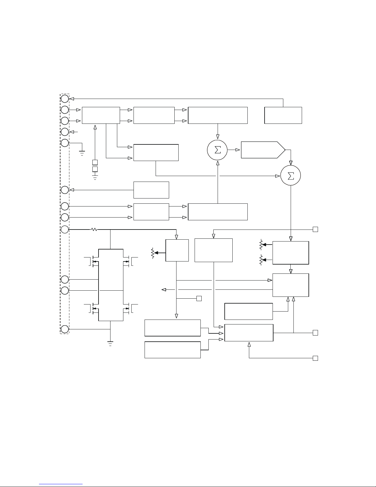
The block diagram in Figure 2 shows the components of the CN0182 servo drive.
8 BIT D/A
CONVERTER
COMMAND POSITION
POSITIO N FE ED BA CK
U/D COUN TER
DECODER
TTL/ANALOG
PROCESSOR
PID
FILTER
OPTICAL
ISOLATORS
+5V
GENERATOR
POSITION
ERROR
CURRENT
SENSE
CURRENT
TRIMPOT
CURRENT
MONITOR
RESET
INPUT
FAULT
OUTPUT
UNDER-VOLTAGE
DETECT CIRCUIT
PWM
SHUT
DOWN
FAULT
LATCH
U/D COUNTER
QUADRATURE
(X4)
ANALOG SLOPE
PROCESSOR
ENCODER
JUMPER
+5V
GAIN
TRIMPOT
OVER-CURRENT
DETECT CIRCUIT
OVER-TEMPERATURE
DETECT CIRCUIT
TO
PWM
TO
PWM
TO
PWM
TO
PWM
TO FETS
MOSFET
BRIDGE
LEVEL
SHIFT
CIRCUIT
-5V
GENERATOR
DAMPING
TRIMPOT
POSITION
LIMIT CIRCUIT
ERROR
3
2
2
1
4
12
11
10
10
5
5
6
6
7
7
8
9
9
Figure 2
MAIN ELEMENTS:
The Command Position U/D Counter is updated by the Step and Direction inputs passed
through the Optical Isolators. The Position Feedback U/D Counter is updated from the
Feedback Encoder. The difference between the two is the Position Error and is applied to the
8 Bit D/A Converter.
4
Page 9
CENTENT COMPANY
The PID Filter separates this signal into its proportional, integral and differential
components. The proportional and differential components have adjustable gain, set by the
Gain and Damping Trimpots. The integral component has a fixed gain. The trimpots control
loop stability; their settings are determined by motor and load properties. The PID
components are summed and applied to the Pulse Width Modulator (PWM). The PWM
converts the PID Filter output voltage into a digital form suitable for a switching amplifier.
The MOSFET Bridge is a high power (80 volts, 20 amps) switching amplifier that drives the
motor.
AUXILIARY ELEMENTS:
The TTL/Analog Processor processes the quadrature encoder inputs through the Quadrature
Decoder into a form usable by the drive. It accepts either TTL digital encoders or analog
sine-cosine encoders depending on the settings of the Encoder Jumper on the Option Header.
If a sine-cosine encoder is selected, the TTL/Analog Processor also passes data to the Analog
Slope Processor. The Analog Slope Processor uses the sine and cosine waveforms to
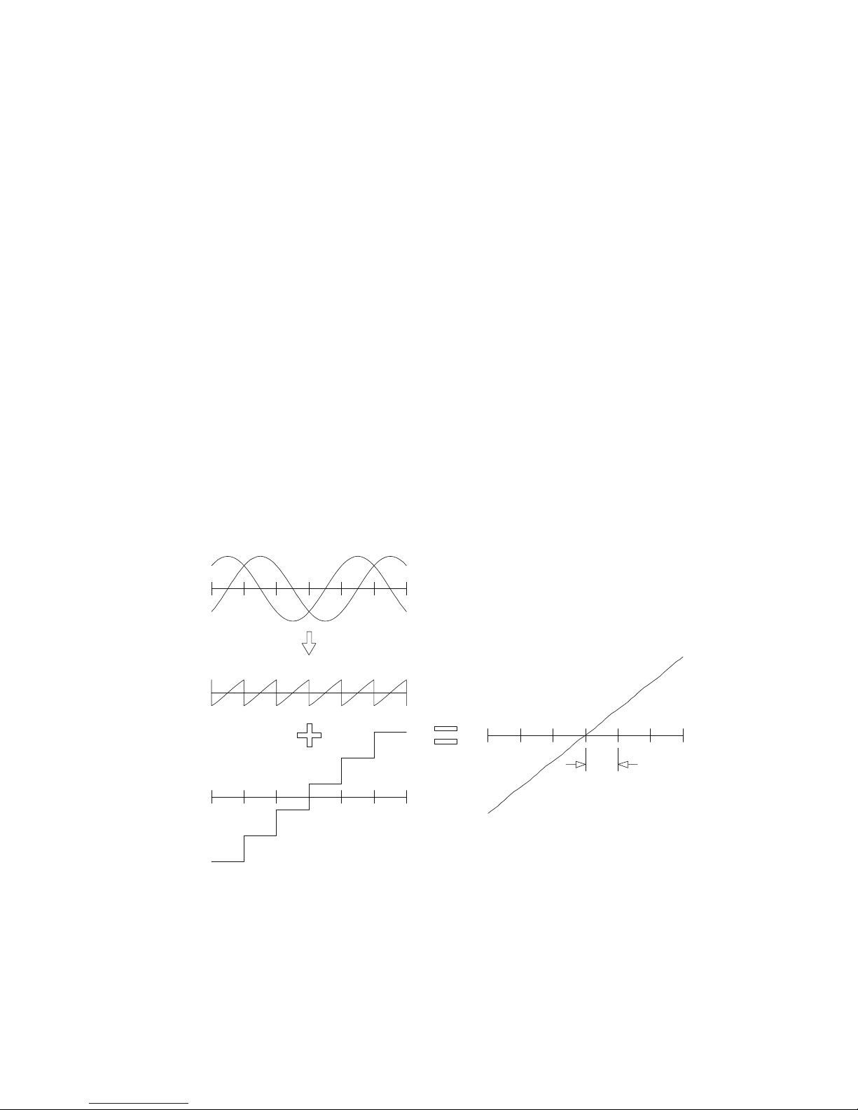
interpolate position between encoder counts. The interpolation signal is summed with the
Position Error to form a continuous, smooth position error, as shown in
Figure 3.
COSINE
CHANNEL
SINE
CHANNEL
SLOPE
PROCESSOR
OUTPUT
D TO A
OUTPUT
10 mV
PEAK TO PEAK
(10 mV STEP)
(+/- 1 VOLT )
(+/- 1 VOLT )
COMPOSITE
FEEDBACK
POSITION
1 INCREMENT
OF MOTION
Figure 3
The use of a sine-cosine encoder has significant advantages over a digital encoder. Because a
digital encoder can only update the Command Position U/D Counter on the encoder signal
edges, the motor position “bounces” between the two adjacent encoder counts when no step
5
Page 10
CN0182 PULSE INCREMENTAL SERVO DRIVE
pulses are being sent. This results in an audible squeal and a vibration equal to one encoder
count. Since a sine-cosine encoder signal contains continuous position information between
encoder counts, the motor will be absolutely still when no step pulses are being sent.
At low speeds where the motion is still incremental (move one step, stop and wait for the
next step), a sine-cosine encoder will result in much smoother operation since each step will
be better damped.
A sine-cosine encoder makes it possible to position the motor to any location, not just the
encoder count edge locations. A 500 count digital encoder results in 2000 resolvable
locations (0.18 degree resolution), but if a 500 line sine-cosine encoder is used, there is also
additional position information between each count location. This interpolated position
feedback can be utilized by driving the Position Error pin on the Option Header (Pin 2).
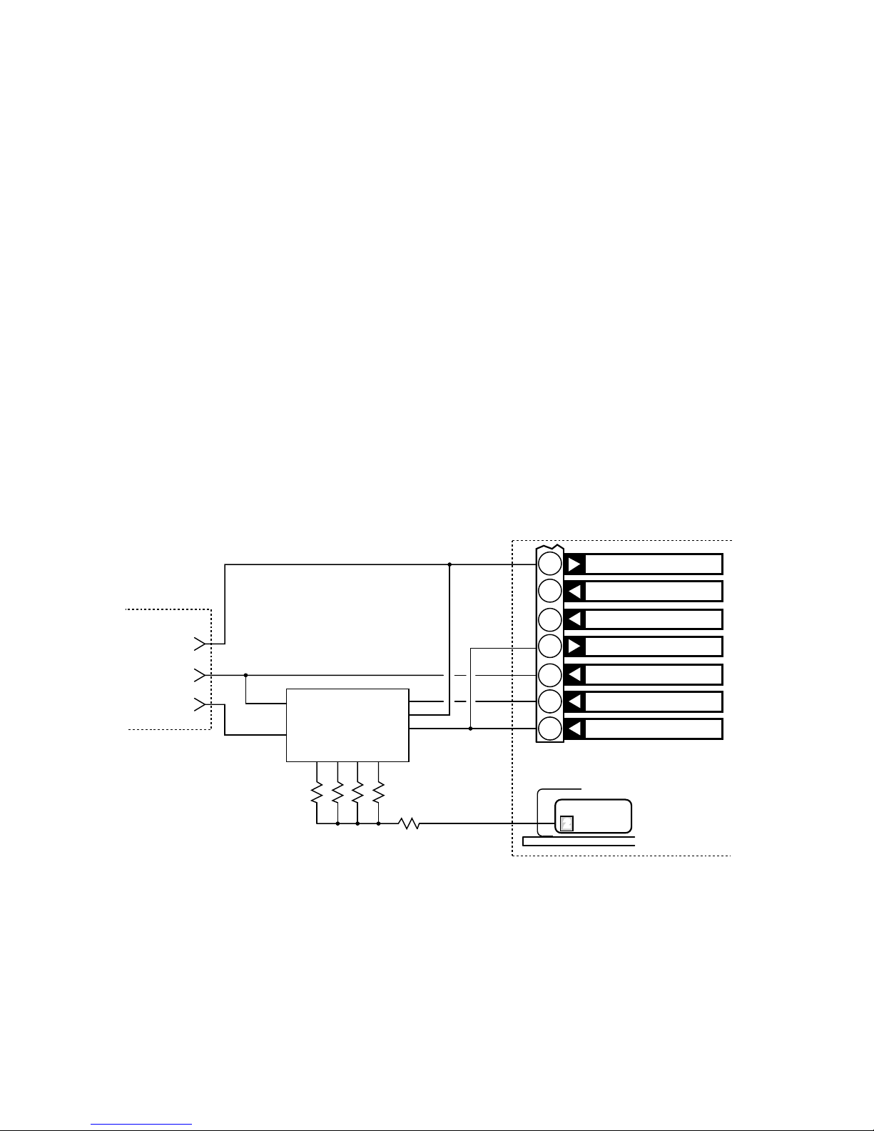
One example, shown in Figure 4, multiplies the encoder line count by a factor of ten. A 500
line sine-cosine encoder has the equivalent resolution of a 5000 count digital encoder. This
results in 20,000 resolvable locations. The user’s U/D Counter divides the Step count by 10
and acts as a low resolution D/A Converter. The full-range output of the D/A is scaled to
equal a one count Position Error step (10 mV), and is summed with the Position Error
voltage.
POSITION ERROR
(PIN 2)
U/D
CL
Q0 Q1 Q2 Q3
R1 R2 R3 R4
R5
UP/DOWN
DECADE
COUNTER
CO
VSS
VDD
R5 = 2.2MEG
R4 = 24.9K
R3 = 49.9K
R2 = 100K
R1 = 200K
GROUND
DIRECTION
INDEXER
CN0182
STEP
ENCODER GROUND
CHANNEL A
CHANNEL B
ENCODE R + 5 V D C
DIRECTION
STEP PULSE
+5 VOLTS DC
13579
46810
2
6
7
8
9
10
11
12
Figure 4
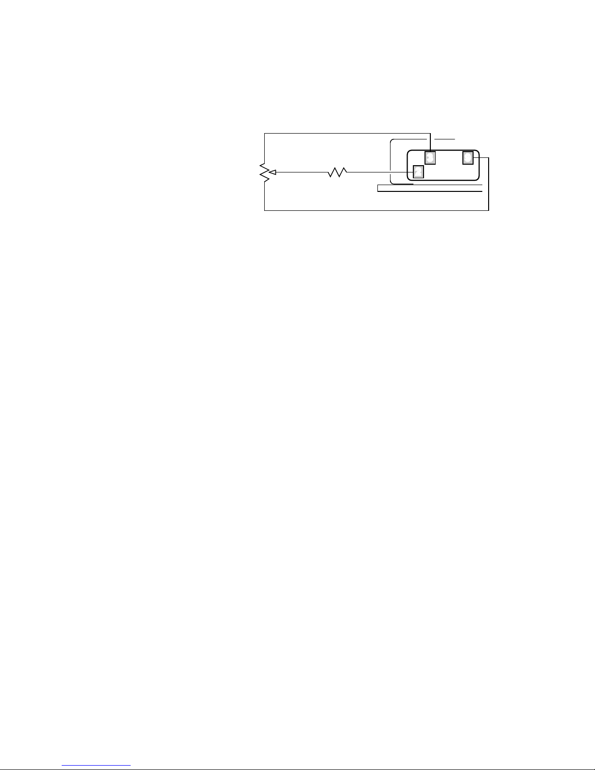
A second example, illustrated in Figure 5, positions a servo motor using a relatively coarse
(inexpensive) sine-cosine encoder and does the fine positioning by driving the Position Error
Pin either manually using a joystick or a potentiometer, or automatically with a user’s closed
loop signal. This is represented by P1 in Figure 5. The required manual adjustment range can
6
Page 11
CENTENT COMPANY
be set from one encoder count to a maximum of ±128 encoder counts, depending on the
value of the Scaling resistor. In either case, the adjustment sensitivity has infinite resolution.
+2.5 VOLTS
GROUND
R1
P1
P1 = ADJUSTMENT POTENTIOMETER
(10K)
R1 = SCALING RESISTOR
(100K)
SCALING RESISTOR
157
46810
2
3 9
Figure 5
Sine-cosine encoders usually require plus and minus power supply voltages for proper
operation. The CN0182 has an on-board –5 V Generator as well as a +5 V Generator to meet
the requirements of both types of encoders.
If a sine-cosine encoder is used, care must be taken to accurately adjust both channels to the
required ±1 volt signal amplitude in order to take advantage of interpolated accuracy. Follow
the encoder manufacturer’s recommended calibration procedures.
If the Position Error Pin is driven, care must be taken to keep noise out of this node. The
input impedance is 100K ohms in parallel with 100 pF. Precautions include shielding the
leads and keeping their lengths short. Use the encoder power supply ground (Terminal 6) as a
common for external circuitry. Do not put any capacitors on the Position Error Pin.
Failure to follow these precautions will result in unstable operation and probable Fault
Protect shutdown.
CURRENT LIMIT:
Motor current is sensed across a Current Sense resistor located at the power supply end of the
MOSFET Bridge. The Current Sense resistor serves the dual purpose of sensing motor
current for current limiting in normal operation as well as sensing short circuit conditions for
the protection circuit.
Because of the location of the Current Sense resistor, the voltage is passed through the Level
Shift Circuit to reference it to ground. The motor current is available at the Current Monitor
Pin on the Option Header (Pin 5). The scale is 10 amps per volt.
Motor current is limited on a pulse by pulse basis by the PWM. The Current Trimpot located
on the side of the drive sets the current limit. The range is from zero to 20 amps. Generally,
the current should not exceed the motor’s rated stall current. Setting the current limit lower
will limit the motor’s available torque and thus its ability to follow Step Pulse commands.
7
Page 12
CN0182 PULSE INCREMENTAL SERVO DRIVE
PROTECTION CIRCUITS:
The CN0182’s response to any fault condition is to turn-off the power transistors that drive
the motor and turn on the Fault Led and the Fault Output Pin on the Option Header (Pin 6).
A major part of the protection loop is the Fault Latch. Its function is to “remember” even
momentary fault conditions, such as a short-circuit, and keep the drive in the protected “off”
state until it is reset by the Reset Input (Pin 7) or the power supply is recycled. All fault
conditions except under-voltage, which is handled by the Under-Voltage Detect Circuit, pass
through the Fault Latch. The fault conditions are:
• Over Current
The Over-Current Detect Circuit monitors the current passing through the drive. When
excessive current occurs, the Fault Latch is set. This will occur if the motor leads short
together or to ground. Normal operation of very high current motors will not set the
Fault Latch because the Current Trimpot limits operating current to 20 amps, which is
below the Over Current Detect trip point.
• Over Temperature
The Over-Temperature Detect Circuit monitors the drive’s temperature. If the
temperature of the drive exceeds 70° C, the circuit sets the Fault Latch. This might
occur if the motor operates continuously at high currents, the drive is poorly heat-sunk
or the ambient temperature is very high. If the cause is high motor current, consider the
possibility the motor may also be overheating.
The protection provided by Over Temperature Detect Circuit is not designed as a
substitute for adequate heat sinking. Repeatedly allowing the drive to overheat and trip
the Fault Latch will cause thermal stress that may eventually lead to failure of the drive.
Under no circumstances allow the temperature of the CN0182 to reach 70° C. For very
high current applications, a fan may also be necessary to provide forced air circulation
to the heat sink.
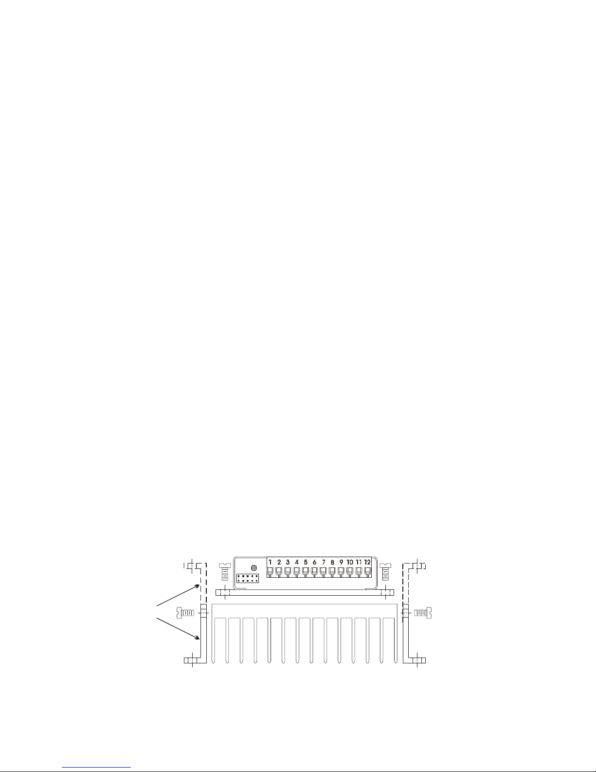
The HSK heat sink kit is available to lower the operating temperature of the drive. The
kit consists of heat sink, side rails and screws to secure the drive and the side rails. The
side rails are reversible, allowing the two mounting configurations shown in
Figure 6.
Contact Centent Company to order the HSK heat sink kit.
side rails
may be
reversed
Figure 6
8
Page 13

CENTENT COMPANY
• Position Error Limit
The Position Error Limit Circuit monitors the difference between the command position
and the actual motor position. If this difference exceeds ±128 counts, the servo lock is
considered broken and the position can not be recovered. The result would be a
runaway motor and possible damage to system components. Before this condition is
reached, the Position Error Limit Circuit sets the Fault Latch, shutting down the drive.
Possible causes of a Position Error Limit trip are many; the most common, and their
remedies are:
1. Unstable Loop
Improperly set Gain and Damping trimpot settings are the causes here. This generally
shows up during the initial setup phase. If the damping setting is too low, the motor
will begin to oscillate. When the oscillation amplitude reaches ±128 counts, the
CN0182 will shut down. Increase the damping setting and try again. If the gain setting
is to low, the drive will be sluggish in responding and an error approaching ±128
counts can develop. Increase the gain setting slightly and try again.
2. Broken Loop
The CN0182 is part of a closed-loop system. The CN0182 drives the motor, the motor
turns the encoder and the encoder sends feedback information back to the CN0182,
completing the loop. Any malfunction in this loop will result in a position error and a
protective shutdown. Verify that the encoder connections to the drive are correct and
that there are no breaks in the wiring or terminals.
3. Insufficient Torque At High Speed
DC motor torque is at a maximum at zero speed (stall torque) and linearly decreases to
zero at the motor’s maximum speed (no-load speed). Consequently, the motor’s ability
to provide torque decreases as speed increases. The options here are to increase the
power supply voltage or use a motor with a higher no-load speed.
Another possible cause may be the frequency limit of the encoder. Many encoders
have a maximum frequency of 100 kHz, or 400,000 counts per second. If a high line
count encoder is used at high speed, this limit may be exceeded. For instance, a 2500
line encoder would be at this limit at 2400 RPM (60 x 100,000 / 2500).
4. Insufficient Torque At Low Speed
Motor torque is directly proportional to motor current. If the motor is unable to carry a
load at low speed, check to see if the Current Trimpot is set too low. If the motor’s
stall current is less than 20 amps, setting the Current Trimpot beyond the stall current
will not help, since it is the motor and not the drive that limits current. The options
here are to get a higher stall current motor (up to 20 amps) or a motor with a higher
torque constant.
9
Page 14
CN0182 PULSE INCREMENTAL SERVO DRIVE
TERMINAL BLOCK FUNCTIONS
Wire of 16-22 gauge is recommended for the connections made to the CN0182. The
insulation should be stripped back 0.25 inches before inserting the wire, to assure good
contact with the connector. No additional terminals or connectors are required on the ends of
the wire. Care must be taken not to damage the screw terminals by over tightening. If
possible use a torque-limiting driver, set to a maximum of 4.5 lb.- in.
The 12 position Terminal Block is grouped by function; the four groups are Motor Group,
Power Supply Group, Encoder Group and Command Group. A detailed description of each
follows:
MOTOR GROUP TERMINALS 1-2
Terminal 1 is the "plus" motor
connection and Terminal 2 is the
"minus" motor connection.
The motor will rotate clockwise when the Direction Input (Terminal 10) is at a logical “0”
(low).
The motor must be a permanent magnet, brush-type DC servo motor. Preferred motors have a
laminated iron armature. The drive requires a minimum inductance of 500 μH. Pancake, cup
and other ironless armature motors have very low inductance (less than 500 μH) and
consequently will have excessive ripple current. This ripple current will cause considerable
motor heating. If these type motors are used, insert a 500 μH inductor in series with the
motor. Make sure the inductor is rated for the maximum current the motor will carry.
The output is a pulse-width modulated (PWM) 20 kHz waveform with voltage amplitude
equal to the power supply voltage. The maximum output current of the drive is ±
20 amps.
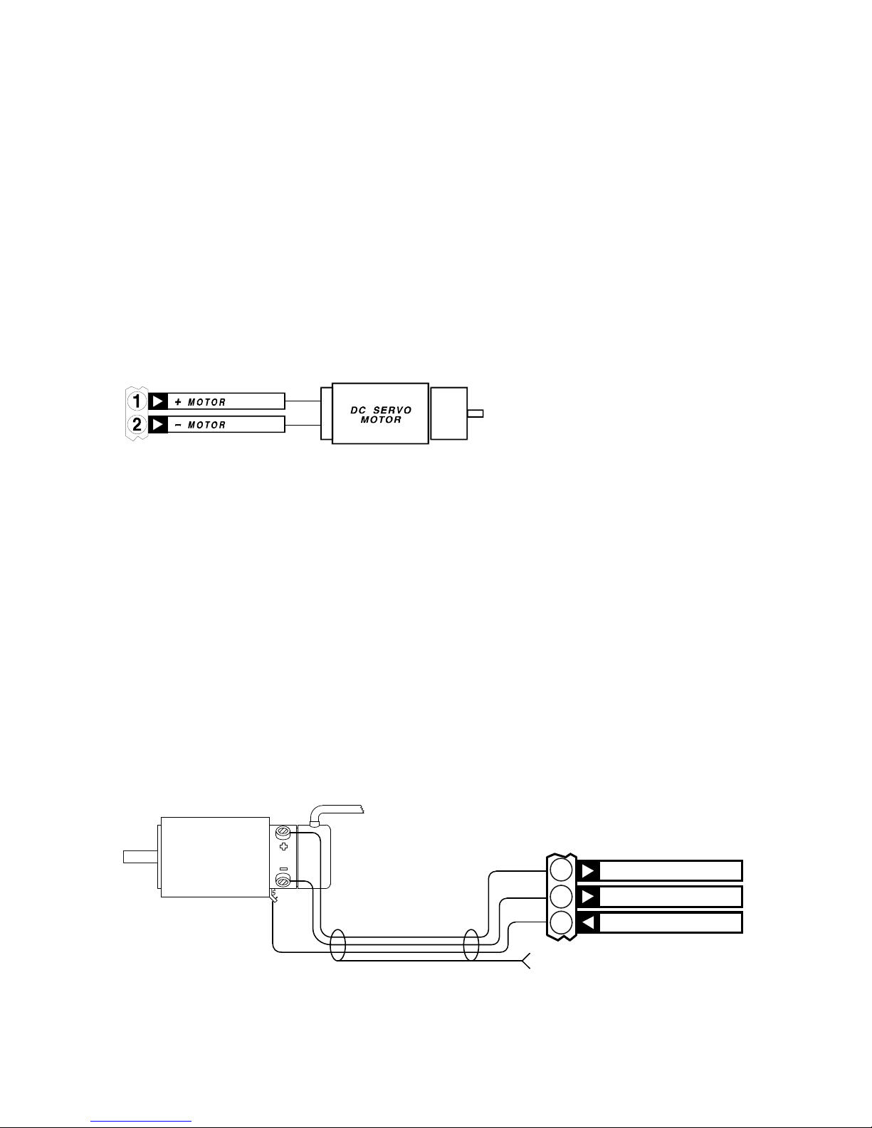
If motor wires longer than 3 feet are required, use a shielded cable. This will limit the amount
of radiated electrical noise that could interfere with other equipment. A three conductor,
shielded cable is recommended. The suggested wiring configuration is shown in Figure 7.
CHASSIS GROUND
SHIELDED CABLE
MOTOR
CASE
+ MOTOR
- MOTOR
SUPPLY GROUND
1
2
3
Figure 7
Two of the wires go to the motor terminals while the third connects to the motor’s case at
one end and to the CN0182’s Supply Ground (Terminal 3) at the other.
10
Page 15
CENTENT COMPANY
The shield should be connected to the chassis ground at one end only! This way the
shield cannot conduct and radiate ground-loop currents.
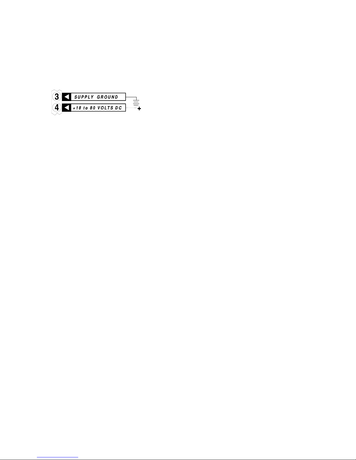
POWER SUPPLY GROUP TERMINALS 3-4
The CN0182 operates on a single voltage DC
power supply, ranging between 18 VDC and
80 VDC.
The power supply may be regulated or unregulated. If the power supply is regulated, it must
have at least 1000 μf of capacitance on the output.
Terminal 4 is the positive input and Terminal 3 is the ground return. The choice of power
supply voltage and current is based on the motor selected. The voltage should be high
enough to run the motor at the maximum speed required by the application. A good first
choice is a power supply voltage equal to the motor’s rated voltage plus two volts to account
for the losses in the drive.
The current rating of the power supply must be sufficient to meet the torque requirements of
the application. A good choice is a power supply with a current rating equal to the motor’s
stall current.
Most motors have a stall current ten times higher than the motor’s continuous rated current.
The continuous rated current is based on the motor’s ability to safely dissipate heat. However
for short periods of time, while accelerating or decelerating, the motor can handle much
higher currents without harm. The power supply must be rated to meet this temporary current
draw.
This makes the power supply up to ten times larger than it otherwise would need to be, since
conventional power supplies cannot deliver current ten times their rated continuous current.
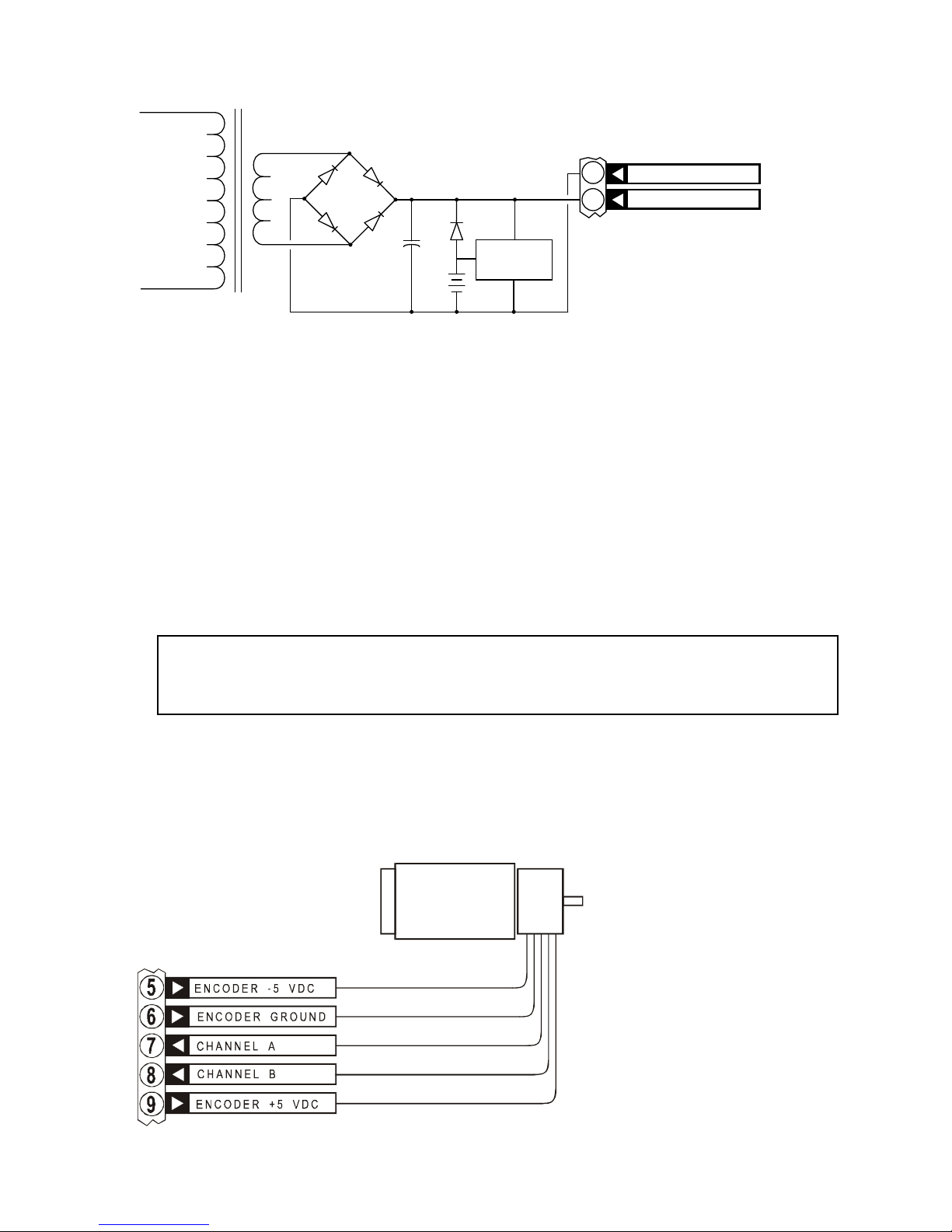
One possible way around this problem is shown in
Figure 8.
The power supply transformer, rectifiers and filter capacitor are sized to provide current that
is slightly greater than the motor’s continuous rated current. A rechargeable battery,
(preferably nickel-cadmium), with a voltage rating a little below the power supply’s voltage
is placed across the power supply output through a diode.
While the motor is drawing current less than the continuous rated current, the diode is
reverse biased and no current flows from the battery.
11
Page 16
CN0182 PULSE INCREMENTAL SERVO DRIVE
D1
D2
D3
D4
D5
B1
C1
T1
115 VAC
BATTERY
CHARGER
SUPPLY GROUND
+ 18 to 80 VO LTS DC
B1 = NICKEL-CADMIUM BATTERY
D5 = B ATTERY DI ODE
C1 = FILTER CAPACITOR
T1 = POWER SUPPLY TRANSFO RMER
D1, D2, D3, D4 = BRIDGE RECTIFIER
3
4
+
+
Figure 8
When the motor begins to draw current in excess of the power supply rating, the power
supply voltage begins to sag and the diode begins to conduct current from the battery,
supplying the temporary current necessary for acceleration. Once the load eases, the power
supply voltage rises and turns off the current from the battery. The trickle-charger restores
the charge drained from the battery.
High currents through long, light gauge wires will result in a significant voltage drop. This
voltage drop can be enough to cause the CN0182 go into Under-Voltage Protect and reset.
This will then cause the motor to develop a Position Error Limit and Fault Output. The result
is the motor will have less performance than expected since it would have to be accelerated
more slowly to avoid drawing this level of current.
IMPORTANT!
Power supply wires must be heavy (16 gauge maximum) and as short in
length as possible. This is especially true for large, high current motors.
ENCODER GROUP TERMINALS 5-9
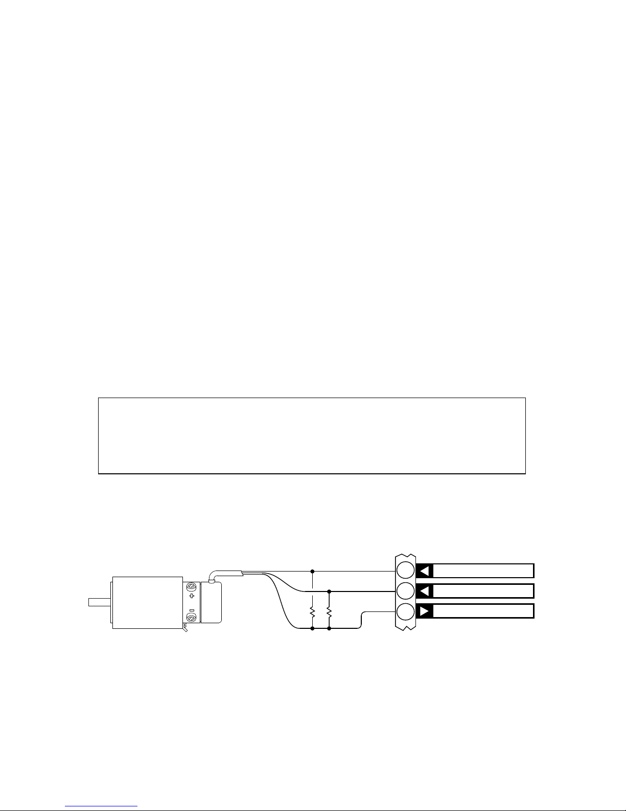
Terminals 5 through 9 form the encoder interface, providing closed loop feedback to the
drive. The CN0182 provides regulated 5 volt outputs to power digital or analog encoders.
Analog encoders normally
require a bipolar power
supply while digital
encoders will generally use
only a +5 volt supply.
Terminal 9 is the +5 VDC
encoder power supply
output required by digital
(TTL) quadrature encoders.
The output provides a
maximum of 100 mA of
current. Most TTL encoders
12
Page 17
CENTENT COMPANY
require substantially less power supply current to operate.
Terminal 5 provides a –5 VDC power supply @ 50 mA maximum. This allows the CN0182
to interface to analog (sine-cosine) encoders. These types of encoders need bipolar (+ and -)
power supplies. Since most encoders use the +5 volt supply to power their LEDs, the –5
VDC current rating of 50 mA is more than adequate.
Terminal 6 is the encoder ground. Use this terminal for the encoder return and ground shield.
Do not use Terminal 3 for encoder return. Terminal 6 connects to a “quiet” ground internally
while Terminal 3 has considerable ground noise that would compromise the noise immunity
of the encoder signal lines and cause erratic operation of the motor.
Terminals 7 and 8 are the channel inputs from the encoder. The inputs can be either TTL
(zero VDC, +5 VDC) levels or analog ±1 volt amplitude sine-cosine inputs. The Encoder
Jumper on the Option Header (pins 9-10) selects between digital and analog encoder
operation. With no jumper in place the inputs must be TTL level signals; with a jumper
present the inputs are analog.
For analog sine-cosine encoders the CN0182 requires the channel outputs to be
±1 volt in
reference to ground. Encoders that do not comply will require external amplification or
attenuation to interface to the CN0182.
Analog and digital encoders may be powered directly from the CN0182 if they
draw less that 100mA @ +5V and 50 mA @ -5V. Encoders requiring higher
voltage or current must be operated by external power supplies.
A special TTL encoder case occurs if the encoder outputs are open collector. Open collector
outputs must have pull-up resistors in order to function. Figure 9 shows how these resistors
are to be connected.
ENCODER +5 VDC
CHANNEL B
CHANNEL A
470
470
7
8
9
Figure 9
The CN0182 performs a "times 4" decoding, resulting in a resolution four times greater than
the line count of the encoder. As an example, a 1000 count per revolution encoder will result
in 4000 positions per revolution.
13
Page 18
CN0182 PULSE INCREMENTAL SERVO DRIVE
While more common, digital (TTL) encoders have the drawback of "hunting" between
adjacent encoder counts. This manifests itself as buzzing or humming, and is most noticeable
when the motor is stopped. Analog encoders avoid this by providing continuous position
information between encoder counts. The result is silent and stable operation while the motor
is stopped.
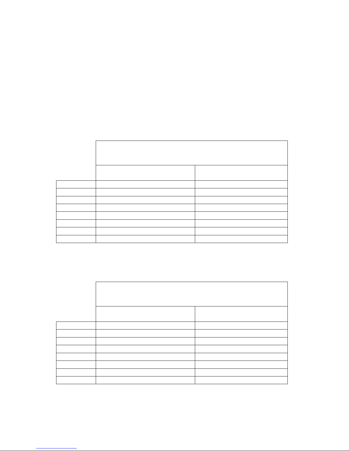
The CN0182 has been tested with numerous TTL and analog type encoders. Below are
several encoders that have performed satisfactorily with the CN0182. This is by no means a
complete list of acceptable encoders.
SINE - COSINE ENCODERS
COMPUTER OPTICAL
PRODUCTS
DYNAMICS RESEARCH
CORP.
MODEL CP-800-5000-F T23DA4EDB2V-1000
LINES 5000 (20,000 counts / rev) 1000 (4000 counts / rev)
CN0182 ENCODER LEAD WIRE ENCODER LEAD WIRE
Terminal 5 WHITE/BROWN (stripe) BLUE
Terminal 6 GRAY/WHITE (stripe) BLACK
Terminal 7 WHITE/ORANGE (stripe) WHITE
Terminal 8 BLUE/WHITE (stripe) GREEN
Terminal 9 BROWN/WHITE (stripe) RED
TTL ENCODERS
HEWLETT PACKARD BEI MOTION SYSTEMS
CO.
MODEL HEDS-5500 A06 MOD5540-25-500
LINES 500 (2000 counts / rev) 500 (2000 counts / rev)
CN0182 ENCODER TERMINAL ENCODER TERMINAL
Terminal 5
Terminal 6 PIN 1 PIN 1
Terminal 7 PIN 2 PIN 2
Terminal 8 PIN 3 PIN 3
Terminal 9 PIN 4 PIN 4
14
Page 19
CENTENT COMPANY
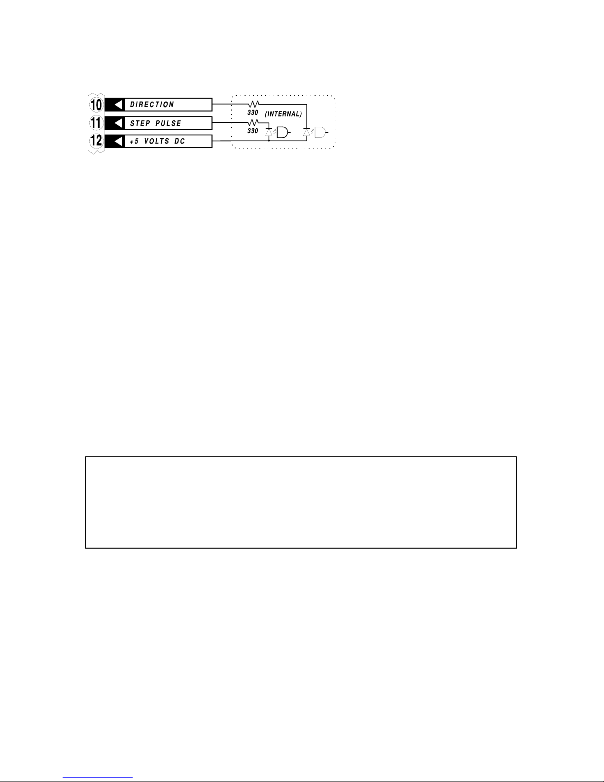
COMMAND GROUP TERMINALS 10-12
The Step Pulse, Direction and +5
VDC inputs form the motion
command interface to the
CN0182.
The motor will move one encoder increment for each step pulse received. The motor moves
in a clockwise rotation if the Direction Input is low at the moment of the step pulse input and
counter-clockwise if the Direction input is high.
The inputs are optically isolated from the rest of the drive circuitry to provide noise
immunity. The high currents, voltages and fast edge times of the motor amplifier generate
considerable electrical noise that would create problems with the indexer logic circuits.
Optical isolation keeps this noise from getting into the indexer.
An indexer or other pulse source generates Step and Direction input to the drive by sinking
the cathodes of the optical isolator LEDs to ground. The external +5 Volts DC used to power
these diodes must be provided by the indexer or pulse source.
The CN0182 uses high-speed opto-isolators that can pass pulse trains up to 1 MHz. It is
necessary that the Step and Direction Inputs have rise and fall times under 50 nano-seconds
to avoid false steps and erratic operation. The opto-isolator driver current sink capability
must be at least 16 mA. This requirement is easily met with standard TTL or 74HC bus
drivers.
IMPORTANT!
Do not run the Command Group wires in a common wiring harness with the Motor
Group wires. Doing so will result in erratic motor behavior because capacitive
coupling of motor waveforms into the Step and Direction input lines would cause
false steps.
If it is necessary to run Command, Encoder or Motor wires longer than 3 feet use shielded
cables. This is particularly important for the Motor wires.
Terminal 10 is the Direction Input. The state of this input is sampled on the rising edge of the
Step Input and determines the direction in which the increment of motion will be taken. If the
Direction Input is a logical “0”, then the step will be in the clockwise direction. If it is a
logical “1”, (+5 VDC or open), then the step will be taken in the counter-clockwise direction
Terminal 11 is the Step Input. A rising edge (0 to +5 VDC) on this input will result in one
increment of motion. The size of this increment is determined by the encoder resolution; a
500 line encoder will yield 0.18 degrees of motion (360° / 500x4 = 0.18°). The direction of
15
Page 20
CN0182 PULSE INCREMENTAL SERVO DRIVE
motion is set by the state of the Direction Input at the time of the Step Input edge. The device
connected to Terminal 11 must be capable of sinking 16 mA of current.
Terminal 12 is the +5 VDC terminal. This input is connected internally to the common
anodes of the Step Pulse and Direction opto-isolator LEDs. By using a separate power
supply, provided by the indexer or pulse generator, electrical isolation between the CN0182
and indexer is maintained.
Terminal 12 is not a 5 Volt output from the CN0182. A separate, external 5-Volt supply must
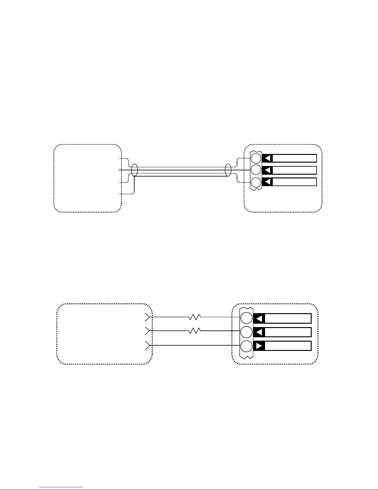
be connected to this terminal. Do not connect Terminal 12 to Terminal 9. A suggested hookup for the Command Group is shown in Figure 10.
+5 VOLTS DC SUPPLY
STEPPULSE OUTPUT
DIRECTION OUTPUT
SHIELDED CABLE
INDEXER CN0182
GROUND
DIRECTION
STEP PULSE
+5 VOLTS DC
10
11
12
Figure 10
If power supply voltages higher than 5 VDC must be used the Step Pulse and Direction
inputs will each require external series resistor to limit the current to the opto-isolators to a
maximum of 10 milliamps. Do not connect a single resistor to Terminal 12 to limit current;
two resistors are required, one to Terminal 10 and one to Terminal 11 (see Figure 11). In this
example a 12-volt supply and 750 ohm external resistors are shown.
750
750
+12 VOLTS DC SUPP LY
STEP PULSE OUTPUT
DIRECTION OUTPUT
INDEXER CN0182
+5 VOLTS DC
STEP PULSE
DIRECTION
10
11
12
Figure 11
Resistor values for common power supply voltages are shown below:
Power Supply External Resistors
12 volts 750 Ω
18 volts 1.3 KΩ
24 volts 2.0 KΩ
16
Page 21
CENTENT COMPANY
Other supply voltages may be used, see Equation 1 to determine the correct external resistor
values for your supply.
330
)010.0(
)5.1(
−
−
=
SUPPLY
EXTERNAL
V
R
Equation 1
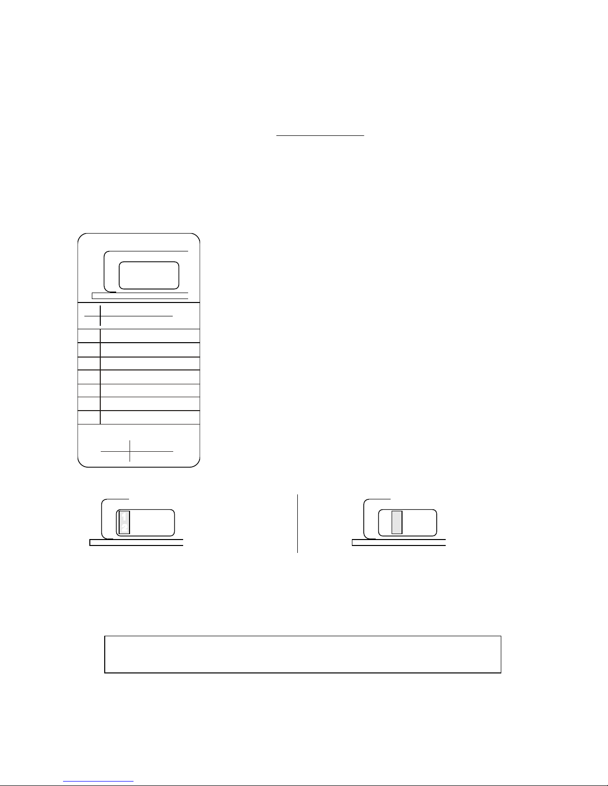
OPTION HEADER
The Option Header is used to configure the CN0182 for the
encoder type and inertial load as well as provide input and output
functions for the drive.
OPTION HEADER
123456789
10
1-2
3-4
2
3
5
6
7
8
9
9-10
ON
OFF
ANALOG
DIGITAL
HIGH INERTIA
LOW INERTIA
POSITION ERROR
+2.5V REFE RENCE
CURRENT MONITOR
FAULT OUTPUT
RESET INPUT
+12 VOLT TEST
GROUND
ENCODER JUMPER
This 10-position (5 x 2) connector is located on the face of the
drive. Pins 1-2, 3-4 and 9-10 are designed as pairs for jumper
blocks. Pins 2 and 3 also have discrete functions. Pins 5-8 have
discrete functions; do not use jumper blocks for these pins.
The following section describes each function and its pin
assignment.
HIGH INERITIA
123456789
10
LOW INERTIA
3456789
10
SYSTEM INERTIA PINS 1-2 & PINS 3-4
1
2
A shorting bar supplied with the drive is used to configure the
CN0182 for load and motor inertia. High inertia is defined as load inertia greater than ten
times the motor’s inertia. To select high inertia, jumper Pin 1 to Pin 2. To select Low Inertia
jumper Pin 3 to Pin 4. Low Inertia is the default setting.
Do not jumper both pairs of pins simultaneously. Jumper only one pair of
System Inertia pins, 1-2 OR 3-4, at a time.
17
Page 22

CN0182 PULSE INCREMENTAL SERVO DRIVE
18
POSITION ERROR PIN 2
3456789
10
1
2
In addition to being the high inertia jumper, Pin 2 also functions
as the Position Error Signal. This output is used to tune the
CN0182 and observe the stability of the system. The voltage on
this pin ranges from 0-2.5 volts. When the motor’s position
matches the command position, representing a zero position error, the voltage on Pin 2 is
1.25 volts.
Each increment of motion difference between the command position and the motor’s actual
position will add or subtract .01 volt to the voltage on Pin 2. A clockwise error will add .01
volt while a counter-clockwise error will subtract .01 volt.
A voltage above 1.25 volts indicates the actual motor shaft position is located clockwise from
the command position. A voltage below 1.25 volts indicates the actual position is located
counter-clockwise of command position. The magnitude of the Position Error is
approximately 10 mV per encoder count.
The voltage on Pin 2 will be 1.25 volts DC, whether the motor is turning or not. Only a
change in load conditions such as an abrupt speed command change, a change in the
direction command while the motor is turning or a suddenly applied or removed load will
cause a transient deviation from this value. Once the motor adjusts itself to the new
conditions, the voltage will return to 1.25 volts.
The stability of the servo can be determined by observing The Position Error voltage with an
oscilloscope while the motor is subjected to abrupt load changes. This can be done by
repeatedly changing the direction command while the motor is turning. See page
23 for how
to tune the servo.
+2.5V REFERENCE PIN 3
45678910
123
Pin 3 is a 2.5-volt reference output used to calibrate the voltage
of the Position Error Signal (on Pin 2). Pin 3 shows the state of
the CN0182’s 2.5 VDC precision voltage reference. It may be
used for external circuits as long as the load current does not
exceed 1 mA. Use Option Header Pin 9 or Terminal Block Terminal 6 for Ground for the
2.5V Reference.
CURRENT MONITOR PIN 5
3
4
6789102
1
5
The voltage on Pin 5 is proportional to the motor current. It is
made available for external monitoring of motor load, which is
proportional to current.
Page 23

CENTENT COMPANY
The ratio is ten amps of motor current per one volt on the output pin. Zero voltage on the pin
implies zero motor current. This voltage is the absolute value of the motor current; it is a
positive voltage regardless of the direction of the motor’s current. Use Option Header Pin 9
or Terminal Block Terminal 6 as Ground for the Current Monitor function.
FAULT OUTPUT PIN 6
Pin 6 goes low (zero volts) when a fault condition is
encountered. This output notifies the user’s equipment that the
CN0182 has shut down and corrective action needs to be taken.
Use Option Header Pin 9 or Terminal Block Terminal 6 for
Ground when monitoring the Fault Output.
345 789
10
2
1
6
The CN0182 enters a fault state under specific conditions. These conditions are:
1. UNDER-VOLTAGE Power supply voltage below 18 VDC
2. OVER-TEMPERATURE Case temperature in excess of 70
°
C
3. OVER-CURRENT Motor current in excess of 20 amps
4. POSITION ERROR An error of more than ±128 counts
The Fault LED provides a visual indication of a fault. Over-temperature, over-current and
position error faults are latched faults. The Fault Output stays low; the CN0182 remains shut
down. The fault state is maintained even if the condition that caused it disappears. The fault
condition may only be cleared by a Reset command (Pin 7) or by recycling the power supply
(power off, power on).
Repeated fault latching means there may be a problem with one or more of the following:
• motor
• motor cable
• encoder
• encoder cable
• excess motor load
• improperly tuned servo
Locate and rectify the problem(s) before continuing the operation of the CN0182. Do not
allow the drive to latch repeatedly, as permanent damage to the drive, motor or power supply
could result.
19
Page 24
CN0182 PULSE INCREMENTAL SERVO DRIVE
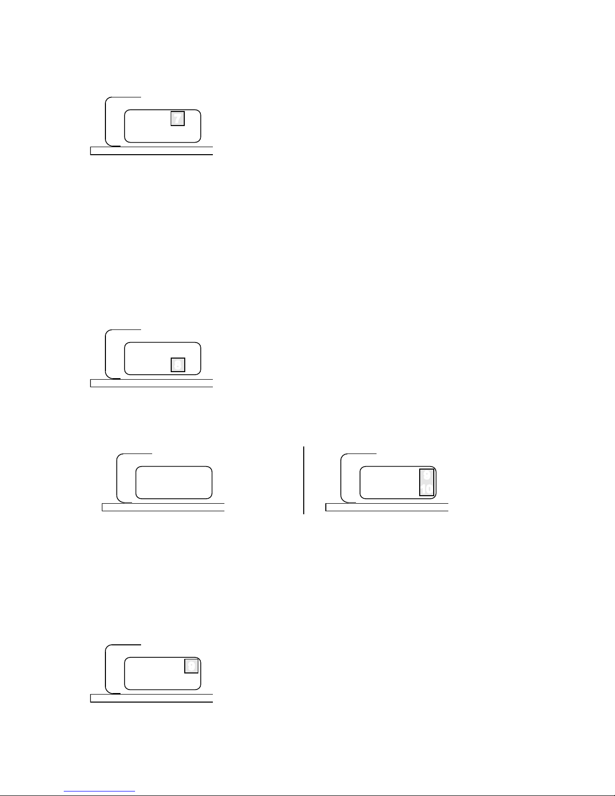
RESET INPUT PIN 7
345
6
89102
17
Pin 7 is normally high (5 VDC). The CN0182 will reset when
Pin 7 input is taken low (shorted to ground). Use Option Header
Pin 9 or Terminal Block Terminal 6 for Ground for this
function.
While reset, the motor is un-powered and freewheeling. The Fault LED will be lit during a
reset. A reset is used to clear a fault. Releasing the Reset Input clears the fault latch and starts
normal operation.
The CN0182 performs a self-reset when it is powered up. The Fault LED will briefly light
every time the CN0182 is powered up.
+12 VOLT TEST PIN 8
Pin 8 is connected directly to the CN0182’s +12 volt regulated
supply. The state of the internal 12 VDC supply may be
observed on this pin. Use Option Header Pin 9 or Terminal
Block Terminal 6 for Ground when monitoring the 12 VDC
supply.
345
6910
2
17
8
ENCODER JUMPER PINS 9-10
345
6910
2
17
8
345
6
2
17
8910
DIGIT AL
ANALOG
To operate the CN0182 with a motor equipped with an analog (sine-cosine) encoders, jumper
Pin 9 to Pin 10. The CN0182 will extract additional position information from the encoder
signals in this configuration. For digital (TTL) encoders, do not connect Pins 9 and 10
together. The default setting for the CN0182 is for digital encoders.
GROUND PIN 9
In addition to serving as a connection for analog encoder
selection, Pin 9 is Ground reference for other Option Header
functions. These include Position Error, +2.5V Reference,
Current Monitor, Fault Output, Reset Input and +12V Test.
Ground reference can also be obtained on Terminal 6 of the Terminal Block. This is the
Encoder Ground. Do not use Terminal 3, Supply Ground, as ground for Option Header
functions.
345
6
102
17
8
9
20
Page 25
CENTENT COMPANY
TUNING THE CN0182 SERVO DRIVE
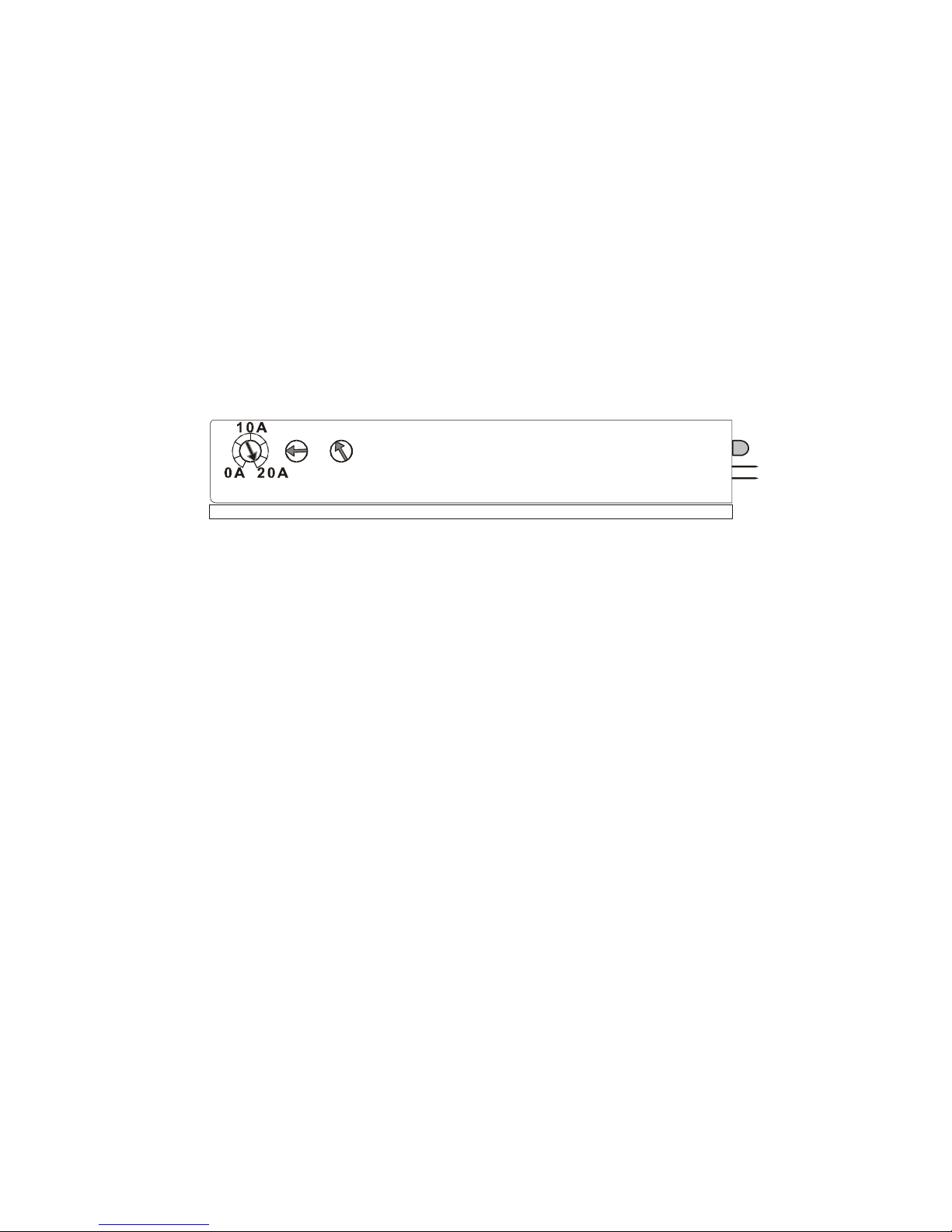
Three potentiometers are built into the CN0182 to set the motor current limit and tune the
servo to the motor and load for stable operation. They are the Current, Gain and Damping
trimpots. They are located on the side of the drive. The function for each trimpot is printed
on the case of the CN0182.
Adjustments may be made with a small slotted screwdriver. The trimpots are
¾ turn from
CCW limit to CW limit. Care must be taken to not force the slots beyond their limits.
CURRENT TRIMPOT
The CN0182 has a maximum current rating of 20 amps. The Current Trimpot adjusts motor
current from zero to twenty amps. The trimpot is linear through its range of travel; turning
the screw to the midpoint sets the current to 10 amps. The full clockwise setting is 20 amps
while the full counter-clockwise setting is zero amps. Turn the trimpot clockwise to increase
maximum motor current. Turn the trimpot counter-clockwise to decrease maximum motor
current.
Normally the Current Trimpot is turned to its maximum setting (all the way CW). Motor
torque is directly proportional to motor current. Setting a current limit below what the motor
can carry will limit the motor’s torque and its ability to drive a load. If a motor cannot drive
the load, a rapidly increasing position error will develop, leading to a premature Position
Error fault shutdown.
Motors that have a stall current less than 20 amps should draw no more than their rated stall
current in normal operation. Set the Current Limit Trimpot to approximately this value to
prevent over-currenting the motor should the direction be suddenly reversed. The Current
Limit Trimpot should also be set to less than the maximum if the driven load might be
damaged when the motor torque exceeds a certain value.
When motor current exceeds the setting of the Current Trimpot, power is interrupted and the
Fault Output and Fault LED turn on. If the motor current exceeds 20 amps, regardless of
trimpot setting, the Fault Output is latched and must be reset to continue operation. See Reset
Input, Pin 7.
The Fault LED will light any time the CN0182 limits motor current. It will be on for the
duration of current limit condition, such as a rapid acceleration or deceleration. It is a
warning that a position error is developing which will lead to a Position Error Fault if further
load is placed on the motor.
21
Page 26
CN0182 PULSE INCREMENTAL SERVO DRIVE
GAIN TRIMPOT
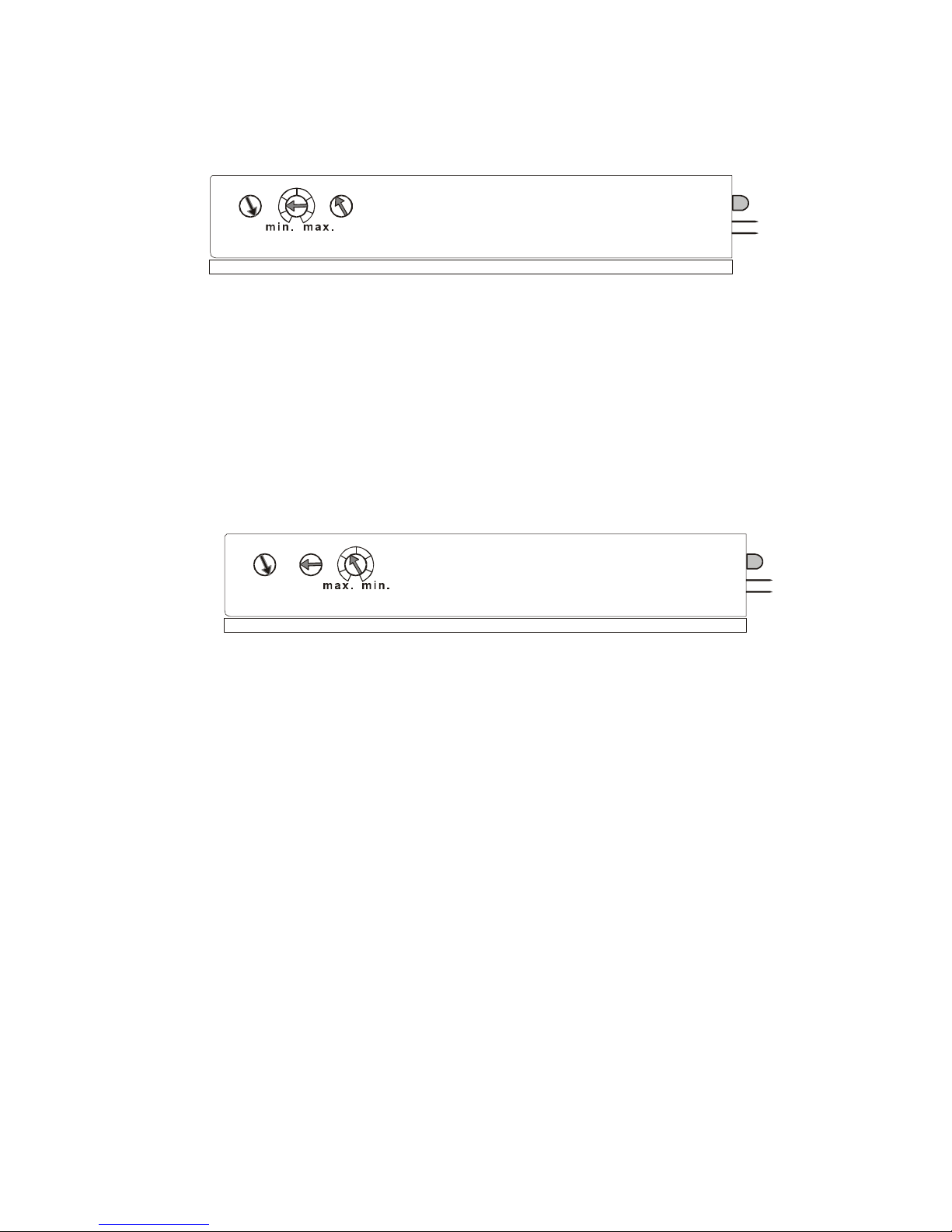
The Gain Trimpot sets the proportional gain coefficient of the PID compensation loop. This
acts to counteract position error introduced into the system by a disturbance. It develops a
"stiffness" to hold the motor at the commanded position. The mechanical equivalent of this
function is a spring. The greater the Gain Trimpot setting, the greater the “stiffness”.
To increase the proportional gain coefficient, turn the trimpot clockwise. To decrease gain
turn the trimpot counter-clockwise.
DAMPING TRIMPOT
The Damping trimpot affects the dynamic behavior of the motor in response to a disturbance.
The mechanical equivalent of this function is a viscous damper or shock absorber. An underdamped motor will oscillate or "ring" after a disturbance, overshooting the command position
repeatedly.
If the system is severely under-damped, the oscillations will increase rapidly in amplitude
until they exceed the Position Error Limit and the CN0182 shuts down.
An over-damped system will take longer than necessary to return to the command position
after a disturbance. Excessive damping also causes greater motor heating and noise since any
position disturbance is responded to over-aggressively.
A properly damped system will return to the command position in the shortest time after a
disturbance. Turning the Damping Trimpot clockwise increases damping. Turning the
Damping Trimpot counter-clockwise decreases damping.
The Damping Trimpot sets the derivative gain coefficient of the PID compensation loop. The
derivative gain coefficient corrects a position error by generating a restoring component
proportional to the rate of position error change; i.e. a derivative of the error.
The gain and damping settings track each other. Increasing the gain setting will require a
higher damping setting; increasing the damping will require a higher gain setting. As a rule,
22
Page 27

CENTENT COMPANY
use the lowest reasonable gain setting, and then adjust the damping to the lowest setting
possible without ringing or overshoot.
INTEGRAL COEFFICIENT
The third element in a PID compensation loop is the integral gain coefficient. The gain is
fixed for this component and is not adjustable by the user. The purpose of the integral
coefficient is to “take up” or eliminate over time any remaining position error. There is
always a position error that the proportional coefficient cannot remove because it becomes
less effective as the position error decreases.
The integral coefficient works by “integrating” over time any remaining position error. This
means any residual error becomes multiplied over time, restoring the motor to the command
position with zero error. The integral gain coefficient is not settable on the CN0182.
The motor will be perfectly still when not commanded to move if sine-cosine encoders are
used. This is because the integral coefficient reduces any position error to zero.
If TTL encoders are used, the motor will bounce between two adjacent encoder count edges
when not commanded to move. This is because there is not position feedback information
between count edges. Any residual position error, no matter how small, is multiplied over
time to a level sufficient to move the motor. The motor then moves until it reaches an
encoder count edge, where it reverses direction until it hits the other constraining encoder
count edge, repeating the process.
Using the minimum Gain Trimpot setting for TTL encoders helps reduce bounce. The higher
the gain the higher the Damping Trimpot setting, both of which contribute to how strongly
and rapidly the motor will bounce between the adjacent encoder count edges. The stronger
the motor bounces, the more torque is required. This results in unnecessary motor heating,
vibration and audible noise.
SERVO LOOP TUNING
A DC servo drive must be "tuned" to the application to achieve optimum system stability.
This consists of adjusting the Gain and Damping Trimpots to the correct values for the
particular motor and load combination the CN0182 is driving.
The tools needed are:
• A STEP and DIRECTION pulse source or 2 FUNCTION GENERATORS
• A 2 channel OSCILLOSCOPE with 10:1 probes
• A small SCREWDRIVER
Begin by connecting the power supply and the encoder to the CN0182. Do not connect the
motor or pulse source yet. Jumper the Option Header for the type of encoder being used (pins
9, 10) and the expected moment of inertia. The default is Low Inertia (pins 3, 4).
Turn on the power supply. The Fault LED should light momentarily when power is applied.
23
Page 28

CN0182 PULSE INCREMENTAL SERVO DRIVE
Test the encoder by turning the motor shaft very slowly. The Fault LED should light when
the shaft is turned more than 128 encoder counts if the encoder is working properly. This
may be a very small part of a revolution of the motor shaft, about 12 degrees or 1/32 of a
revolution for a 1000-line encoder.
Turn the Gain Trimpot to the “9 o’clock” position and the Damping Trimpot to the “11
o’clock” position. See the graphics on page 22 for orientation of these trimpots. They have a
small arrowhead pointer at the end of the screwdriver adjustment slot. The “9 o’clock”
setting of the Gain Trimpot positions the pointer parallel to the base plate of the drive with
the arrow pointing to the left as you face the trimpot. The Damping Trimpot “11 o’clock”
position is also shown.
Turn the power supply off and connect the motor. Turn the power supply back on. If the
motor jerks momentarily and The Fault LED comes on, turn the supply off and reverse the
motor lead connections.
With the power supply on, the Fault LED should be off and the motor should be stopped. It is
normal for the motor to make a slight squealing sound, particularly if a TTL type encoder is
used. Gently try turning the motor shaft; it should resist being turned.
Turn the power supply off. Connect the pulse source to the CN0182’s Step, Direction and +5
Volts DC inputs. If Function Generators are used, do the following:
Set both Function Generators to the square wave setting and adjust the outputs to a
±5 volt amplitude. One generator will drive the Direction Input while the other will
drive the Step Input. Set the Direction generator output to about 1 Hz.
Set the Step generator to a frequency range setting that will turn the motor about five
revolutions per second full scale. This frequency depends on the encoder line count;
1000-line encoder will require 20 kHz to turn at this speed. Turn the frequency dial to
the minimum on this range setting.
Connect both generators’ ground leads to the CN0182’s +5 Volts DC terminal
(Terminal 12). Connect the Direction generator’s output to the Direction Terminal
(Terminal 9) and the Step generator’s output to the Step Terminal (Terminal 10).
Make sure both generators are on.
If an indexer is used instead of Function Generators, follow the procedure described in the
Command Group section on page
15 to connect the indexer to the CN0182. The indexer must
be setup to send a continuous stream of motion instructions. Each instruction should be
scaled to move the motor shaft at about five revolutions per second for approximately
½
second. The direction of the move must alternate with each instruction. The rate of
acceleration of the moves should be set to a maximum value.
Connect the oscilloscope channel 1 probe to Pin 2 (Position Error Output) on the Option
Header. Connect the probe ground lead to Terminal 6 (Encoder Ground) on the Terminal
Block. Connect the oscilloscope channel 2 probe to Terminal 9 (Encoder +5 VDC) on the
Terminal Block and its ground lead to Terminal 12 (+5 Volts DC) on the Terminal Block.
24
Page 29

CENTENT COMPANY
Set the oscilloscope’s Channel 1 Volts/Div to .2 volts and set Channel 2 Volts/Div to 2 volts.
Zero both channels to the bottom line on the display grid. Set both channels to DC Coupling.
Set the Vertical Mode to display Channel 1 only. Set the time-base Sec/Div to 10
milliseconds. Set the Trigger Source to Channel 2 and the Trigger Mode to Normal. Adjust
the Trigger Level until you see a once per second sweep on the scope display.
Turn the power supply on. The motor should turn slowly and reverse direction twice a
second. The oscilloscope display should show a negative going “blip” followed by a flat
trace at the 1.25 volt level, or about 6.25 display grid lines up from the bottom. If the “blip”
at the beginning of the trace is very small or can’t be seen, slowly increase the Step generator
frequency until the height of the blip is about 2 grid lines high. The motor should be turning
more rapidly now. If the display trace starts as a positive going blip, change the Trigger
Slope setting on the oscilloscope. If the servo is tuned correctly, the scope display should
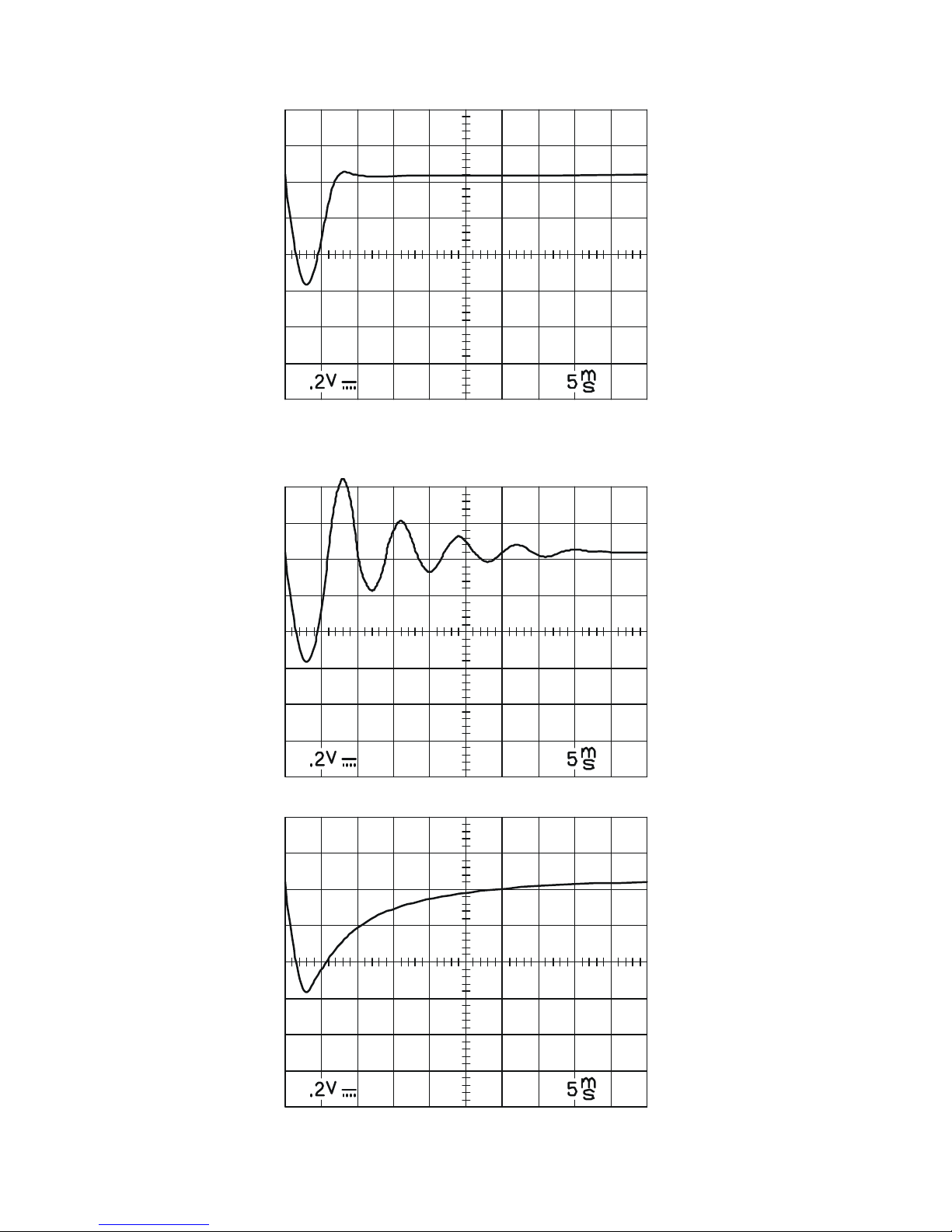
look like Figure 12 on page 26.
If the oscilloscope display looks more like Figure 13, the servo-loop needs more damping.
Either turn the Damping Trimpot slightly clockwise or turn the Gain Trimpot counterclockwise until the display most closely matches Figure 12.
Turning the Damping Trimpot up will increase rate at which the motor will “hunt” when it is
stopped, increasing motor heating and audible noise when stopped. Turning the Gain Trimpot
down will decrease loop “stiffness” or its ability to closely track the commanded speed. This
shows up on the display as a slight waviness of the rest of the sweep after the initial blip.
Either way the loop is stable.
If the oscilloscope display looks more like Figure 14, the servo-loop needs less damping.
Either turn the Damping Trimpot down or turn the Gain Trimpot up until the oscilloscope
display matches Figure 12.
The tuning setup is now complete. The Current Trimpot may now be adjusted to a lower
level if desired. The Damping Trimpot and Gain Trimpot settings may need to be changed if
the motor’s load moment of inertia changes significantly.
25
Page 30
CN0182 PULSE INCREMENTAL SERVO DRIVE
Figure 12 - optimum damping
Figure 13 – under-damping
Figure 14 – over-damping
26
Page 31

CENTENT COMPANY
INTERPRETING Figure 12 – Optimum Damping
Figure 12 - optimum damping, reveals considerable detail about the motor’s dynamic
response. In this example, a 1000-line encoder was used on a size 23 servo motor with no
load attached. The power supply was 28 VDC and the Step generator frequency was 20.0
kHz for a motor speed of five revolutions per second.
By changing the direction while keeping the step rate constant, the motor is being asked to
reverse instantly. This is a physical impossibility.
The motor responds by decelerating as rapidly as it can, reversing direction, and then
accelerating in the new direction until it approaches the moving command position. It then
decelerates until its speed and position exactly matches the moving command position in the
new direction.
In this example, the time to go from five revolutions per second in one direction to five
revolutions per second in the opposite direction takes just three milliseconds. At this point,
the motor is 5.4 degrees behind the moving command position. In
Figure 12 this is the
bottom of the Position Error notch ((0.6 volt amplitude
÷ .01 volts per increment of motion)
x .09° per encoder count = 5.4°).
From 3 mS to 7 mS the motor catches up to the moving command position. In Figure 12 this
is the upward slope from the bottom of the notch until it crosses the 1.25 volt level.
From 7 mS to 10 mS the motor slightly overshoots (by .36 degrees) and then returns to match
the moving command position. From then on the motor’s speed and position matches the
moving command position within .09 degrees. This outperforms a step motor by a
considerable margin.
PICKING A MOTOR
It can be a challenge to pick the right motor for an application. This process can be made
easier if a few fundamentals are observed.
The first requirement is to determine how much power will be needed to drive the load. First
measure or calculate the maximum torque required, in ounce-inches, and the maximum
speed, in revolutions per minute (RPM), at which the motor must deliver this torque. Use
Equation 2 to calculate the power in Watts necessary to accomplish this.
8.1351
INOZRPM
WATTS
TS
P
−
×
=
Equation 2
Next, select a motor voltage rating, typically 24 VDC or 48 VDC. Use Equation 3 to pick the
Stall Current, in amps, of the smallest possible motor to drive this load.
27
Page 32

CN0182 PULSE INCREMENTAL SERVO DRIVE
MOTOR
WATTS
STALL
V
P
I
×
=
4
Equation 3
the terminal resistance is preferred as a means of selecting the motor instead of the stall If
current, use Equation 4.
STALL
MOTOR
TERMINAL
I
V
R =
Equation 4
inally, select a motor with a no-load speed that is at least twice the maximum speed
s an example, let’s say a 24 VDC motor is to drive a load that requires 125 oz-in of torque
• Power = 161.8 Watts = [(Equation 2): (1750) x (125) / 1351.8]
ps =
his choice works well if the peak torque (125 oz-in) is required for short time periods, such
OTOR FUNDAMENTALS:
et’s start by describing an ideal DC brush type motor and then adding what makes it a real
An ideal motor behaves very differently than a real motor, and the difference is due to the
ab
F
necessary to drive the load.
A
at 1750 RPM. Using the given equations, we calculate the following:
• Stall Current = 26.97 Am [(Equation 3): 4 (161.8) / 24]
• Terminal Resistance = 0.89 Ohms = [(Equation 4): 24 / 26.97]
• No-Load Speed = 3500 RPM = [2 x (1750)]
T
as acceleration or deceleration. While this motor is delivering 161.8 Watts to the load, it is
also dissipating the same amount as heat. A motor this size would soon overheat if it were
required to deliver this power continuously. The continuous torque rating of the motor must
be observed, which typically will be 1/5 of the peak torque value, or 25 oz-in (125 oz-in / 5 =
25 oz-in).
M
L
motor. An ideal motor has zero ohms terminal resistance. Like a real motor, it has a speed
proportional to the power supply voltage and will draw current from the supply proportional
to the load torque. As with a real motor, output power is torque multiplied by speed and can
be expressed as horsepower or watts.
sence of terminal resistance. As an example, let’s say our ideal motor has a speed constant
of 100 RPM per volt and a torque constant of 13.52 oz.-in. per amp, which are also
reasonable values for a real motor. In our example a 10 VDC power supply is applied to the
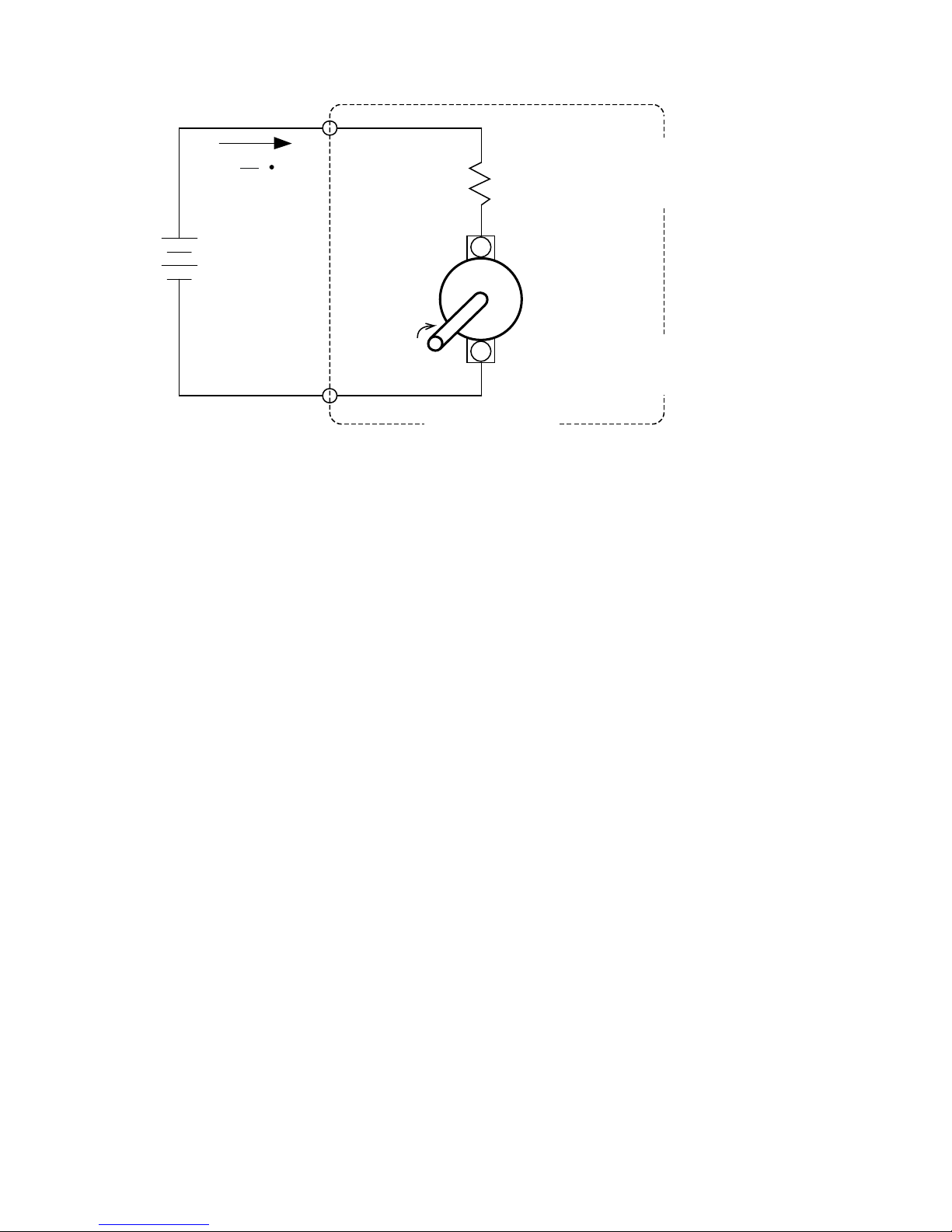
motor in Figure 15.
28
Page 33
CENTENT COMPANY
IDEAL MOTOR
+
-
R
1
T
K
TI =
LOAD
TORQUE
POWER
SUPPLY
V=IxR
resistor
REAL MOTOR
R = TERMINAL RESISTANCE
K = 13.52 OZ-IN/AMP
K=100RPM/VOLT
TORQUE
SPEED
motor supply resistor
V=V -V
RPM = K x V
vmotor
-
+
Figure 15
The ideal motor turns at 1000 RPM with a 10 VDC power supply and its speed does not
change at all with load. It can drive an unlimited load, drawing unlimited current, and as long
as the power supply maintains voltage, the speed will remain at 1000 RPM. The motor
efficiency is 100% regardless of load simply because zero ohms dissipates no power. All
electrical power going into the motor is converted to mechanical power with perfect
efficiency. In short, speed is completely unrelated to torque, both are unlimited and
conversion efficiency is 100%.
A real-word motor differs from an ideal motor because it has electrical resistance. In fact, a
real motor can be modeled as an ideal motor in series with a resistor.
If we take our previously described ideal motor and add a 1 ohm resistor (a reasonable value)
in series, it now very closely resembles a real motor. It will still draw a current proportional
to torque, but now the current passes through this resistor as well. The maximum current the
motor can draw is now limited by Ohm’s law to 10 amps, and is called the stall current.
Motor torque is also limited to the stall current times the torque constant, and is called the
stall torque.
The current passing through this resistor has three consequences. The resistance develops a
voltage drop across it (V = I R ), it dissipates power (W = I
2
R ) and it limits the motor’s
power output for a given power supply voltage.
The voltage drop subtracts from the power supply voltage, leaving less voltage across the
ideal motor. The motor now runs more slowly. At stall current, all the voltage is across the
resistor leaving nothing for the ideal motor. Since the ideal motor’s speed is proportional to
voltage, by definition the motor speed at stall is zero.
The power dissipated is subtracted from the total power going into the motor, leaving the
balance to be converted to mechanical power. This means efficiency becomes less than 100%
at any applied load and the motor generates heat.
29
Page 34
CN0182 PULSE INCREMENTAL SERVO DRIVE
POWER SUPPLY = 10 VD
C
TERMINAL RESISTANCE = 1 OHM
TORQUE CONSTANT = 13.52 OZ-IN/AMP
SPEED CONSTANT = 100 RPM/VOLT
SPEED
1000 RPM
500 RPM
SPEED
TORQUE
67.6 OZ-IN 135.2 OZ-IN
MECHANICAL
PEAK POWER
25 WATTS
CURRENT
10 AMPS
5 AMPS
CURRENT
Figure 16
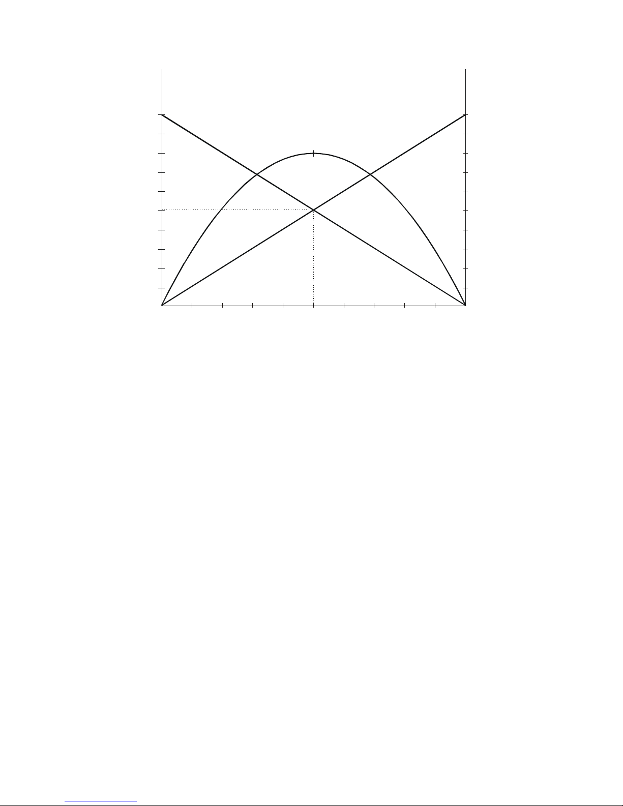
Mechanical power is the product of speed times torque. A motor running at its no-load speed
is producing zero power since torque applied is zero. At the other extreme, a stalled motor is
producing zero power as well, since its speed is zero. Therefore, it can be inferred that output
power must increase from zero, reach a peak, and then fall back to zero again as applied
torque goes from zero to stall. In fact the power versus torque curve is parabolic and peaks at
½ of stall torque (Figure 16).
Motor efficiency is the percentage of electrical power delivered to the motor that is converted
to mechanical power; the rest is dissipated as heat. As seen above, the motor delivers
maximum output power at one half of its stall current. At this point the series resistor has half
of the power supply voltage across it, leaving the other half for the ideal motor. Since the
same current flows through both, half the power is converted to heat. This means the real
motor efficiency cannot be more than 50% at peak power output.
If there were no friction in the motor, efficiency would be 100% for an infinitesimal torque
load, decreasing linearly with load to 0% at stall torque.
The continuous rated torque is typically one tenth of the motor’s stall torque. Because motor
heating goes up with the square of the current (W= I
2
R), peak heat dissipation in a ty pical
motor is 100 times higher than what the motor can dissipate continuously. Heat dissipation at
peak motor power output is 25 times the motor’s continuous dissipation. Be careful what
percentage of time the motor must operate above its continuous rated torque!
30
Page 35

CENTENT COMPANY
SPECIFICATIONS
MIN MAX UNITS
ELECTRICAL
Supply Voltage 18 80 VOLT (DC)
Current (continuous) -- 20 AMP
Step Pulse Frequency 0 1 MHz
Opto-isolator
current 10 10 mA
Encoder
Frequency 0 200 kHz
Servo Lock Range -128 +128 COUNTS
Signal Level
TTL encoder 0 5 VOLT (DC)
analog encoder -1 +1 VOLT (DC)
Supply Current
+5 Volt Supply -- 100 mA
-5 Volt Supply -- 50 mA
ENVIRONMENTAL
Operating temperature -20 75 °C
-4 167 °F
Humidity 0 100 %
Shock -- 100 G
MECHANICAL
Weight 17 19 ounce
482 539 gram
Terminal Screw Torque 4.5 lb/in
Size (LxWxH) 4.75 x 4.00 x 0.85 inch
121 x 102 x 22 millimeter
Mounting hole centers 3.625 x 3.625 inch
92 x 92 millimeter
Mounting screw size 6 8 #
31
Page 36
CN0182 PULSE INCREMENTAL SERVO DRIVE
32
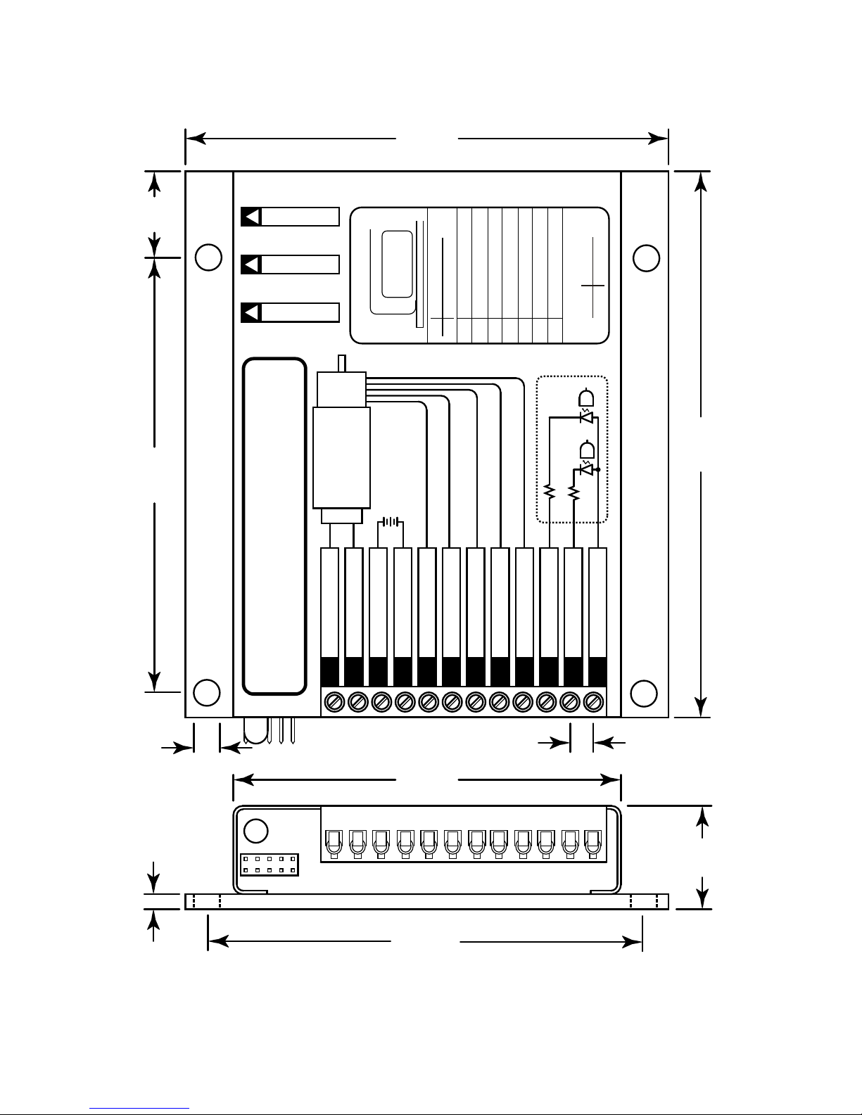
FULL SCALE DRAWING
+ MOTOR
-MOTOR
SUPPLY GROUND
+18 to 80 VO LTS DC
ENCODER - 5 V DC
ENCODER GROUND
CHANNEL A
CHANNEL B
ENCODER +5 VDC
DIRECTION
STEP PULSE
+5 VOLTS DC
CENTENT CN0182
PULSE INCREMENTAL SERVO DRIVE
123456789101112
3.625”
92.1mm
4.0”
101.6mm
4.5”
114.3mm
3.625”
92.1mm
0.85”
21.5mm
0.125”
3.2mm
3.25”
82.6mm
0.186”
4.7mm
0.20”
5.1mm
0.7”
17.8mm
330
330
(INTERNAL)
+
MAX. 115% OF
MOTOR RATED
VOLTAGE
(50 mA MAX. )
BRUSH TYPE
DC SERVO
MOTOR
(100 mA MAX.)
D
A
M
P
I
N
G
G
A
I
N
CUR
REN
T
OPTION HEADER
1
2
3
4
5
6
7
8
9
10
1-2
3-4
2356789
9-10
ON
OFF
ANALOG
DIGITAL
HIGH INERTIA
LOW I NERT IA
POSITION ERROR
+2.5V REFERENCE
CURRENT MONITOR
FAULT OU TPUT
RESET INPUT
+12 VOLTTEST
GROUND
ENCODE R J UMPER
Figure17
 Loading...