

Page 1
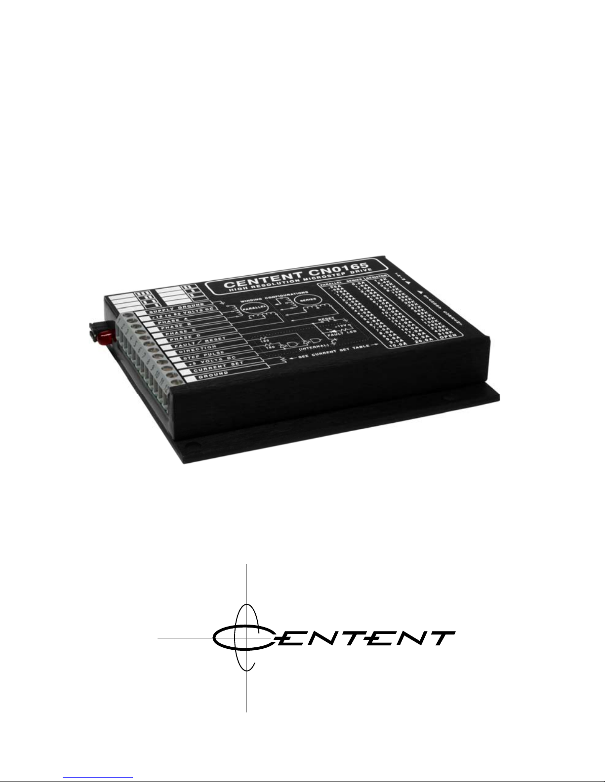
CN0165
OPERATING MANUAL
HIGH RESOLUTION MICROSTEP DRIVE
3879 SOUTH MAIN STREET 714-979-6491
SANTAANA, CALIFORNIA 92707-5710 U.S.A.
0 M P A N Y
Page 2

This manual contains information for installing and operating the following
Centent Company product:
CN0165 Microstep Drive
Centent and the Centent Company logo are trademarks of Centent Company.
Other trademarks, tradenames, and service marks owned or registered by any other
company and used in this manual are the property of their respective companies.
Copyright © 2019 Centent Company
3879 South Main Street
Santa Ana, CA 97207
All Rights Reserved
Page 3

GENERAL DESCRIPTION...............................................................................1
LOCATION OF COMPONENTS......................................................................2
INSTALLATION
Heat Sinking .................................................................................................3
Power Supply................................................................................................ 4
Motor lead color codes................................................................................. 8
Fault/Reset....................................................................................................9
Direction..................................................................................................... 10
Step Pulse ...................................................................................................10
+5 VDC ......................................................................................................10
Current Set.................................................................................................. 11
Current Set Table........................................................................................13
Option Header............................................................................................14
OPERATION
Standby Current Trimpot............................................................................ 15
Offset Trimpot.............................................................................................15
Fault Led .................................................................................................... 16
Power-On Reset.......................................................................................... 16
Under-Voltage Lockout ..............................................................................16
PERFORMANCE
Microstepping............................................................................................. 16
Anti-resonance............................................................................................17
Torque and Power...................................................................................... 18
Motor Winding Configuration....................................................................19
Power Supply Voltage ................................................................................22
Power Supply Current................................................................................22
Motor and Drive Heating ...........................................................................23
ACCURACY
Motor Tolerances .......................................................................................23
Motor Load.................................................................................................24
Motor Linearity...........................................................................................24
Current Profile Option ...............................................................................25
SPEED-TORQUE CURVES............................................................................25
FULL SCALE DRAWING ...............................................................................40
SPECIFICATIONS ..........................................................................................41
INDEX............................................................................................................... 42
Page 4

Page 5

1
GENERAL DESCRIPTION
The Centent CN0165 is a high resolution step motor drive designed for the operation of
hybrid PM step motors rated from 0.1 to 20 amps per phase. The CN0165 operates on a
supply voltage of 18-80 volts DC. Drive output current ranges from 0.1 to 10 amps per
phase. Maximum step input frequency is 1.5 MHz. The minimum on or off time for the
step input is 300 nanoseconds. Motor winding inductance as low as 0.5 millihenrys is
permitted.
The CN0165 features eight selectable microstep resolutions per drive. Available
resolutions range from full-step to 256 microsteps per full step. The step resolution is
selected by jumpering the option header located on the face of the drive.
The CN0165 is capable of delivering up to 1.5 million microsteps per second to the step
motor. The pin-out of the CN0165 is compatible with other Centent step motor drives.
The design of the CN0165 is a combination of recirculating current and non-recirculating
current type chopper drives. It features electronic viscous damping for control of motor
mid-band instability (anti--resonance) and a high-speed torque boost circuit. MOSFET
transistors are utilized in the 'H' bridge output circuit. Automatic current standby, easily
adjustable from zero to full current, reduces motor phase current while the motor is at
rest. The combination of these features results in an extremely efficient step motor drive
with minimum motor iron losses (heating).
The CN0165 uses high speed opto-isolators for the Step Pulse and the Direction inputs to
provide maximum noise immunity. The Step Pulse and Direction inputs are compatible
with TTL drivers and require no additional components.
Motor stepping occurs on the high to low transition of the Step Pulse Input. The
Direction Input hold time is one microsecond after the active edge of the Step Pulse
Input. The Direction Input can be updated simultaneously with the active transition of the
Step Pulse Input.
Over-current conditions like winding shorts, overheating conditions such as insufficient
heat sinking, and under-voltage conditions like power supply failure are sensed by the
CN0165. When any of these conditions occur the CN0165 shuts down, activating the
Fault Output and lighting the Fault LED located on the face of the drive.
The Centent CN0165 High Resolution Microstep Drive is compact; measuring 4.75
inches x 4.00 inches x 0.85 inches (121mm x 102mm x 22mm). It comes encapsulated in
a heat conductive epoxy and encased in an anodized aluminum cover. This results in a
rugged package that resists abuse and contamination, suitable for harsh environments.
Page 6
CENTENT CN0165 MICROSTEP DRIVE
2
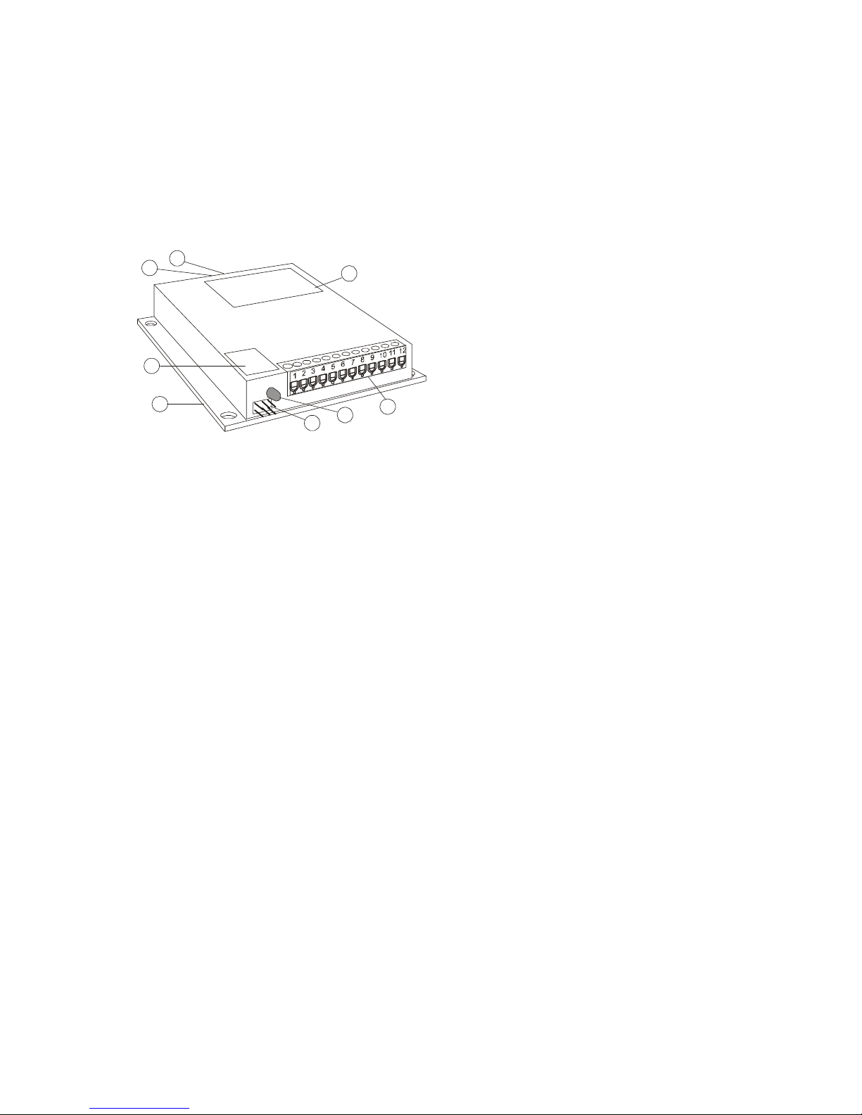
LOCATION OF COMPONENTS
(1) MOUNTING PLATE
The base plate also serves as a heat sink, although additional heat sinking may be
required. The temperature of the drive must never exceed +70°C (+158°F). Four
mounting holes on 3.625 inch (92 mm) centers are provided to secure the drive to the
heat sink or the user’s equipment.
(2) OPTION HEADER
A six pin header selects the active
microstep resolution or current profile.
The user jumpers the desired pins with the
shorting bars supplied with the drive.
Eight resolutions or current profiles are
available in each drive. The value for each
selection is printed in the Resolution
Table (see Page
X14X). There are 21
microstep resolutions available for the
CN0165 Microstep Drive.
Figure 1 - Component location
(3) FAULT LED
This light emitting diode turns on when the CN0165 is in a fault mode. The fault status is
also available on the Fault/Reset Terminal of the connector (see page
X9X). A fault
condition is cleared by shorting the Fault/Reset Terminal to ground potential or by
recycling the power supply (power off, power on).
(4) TERMINAL CONNECTOR
A 12 position terminal strip provides the connections for the power supply, the motor, the
Current Set and the indexer interface (Step Pulse and Direction inputs). Care must be
taken not to over-torque the terminal screws to prevent damage to the connector.
(5) RESOLUTION TABLE
The Resolution Table provides a diagram of each Option Header configuration, and the
resolution associated with it. A maximum of eight of the twenty-one possible step
resolutions are available in each CN0165.
(6) CURRENT SET TABLE
This table provides the user with standard 5% values for the Current Set Resistor
connected between terminals 11 and 12 of the Terminal Connector. Values are given for
Parallel and Series operation from 0.25 to 20 amps per phase.
(7) OFFSET TRIMPOT
This is a fine-tuning adjustment for high microstep resolutions. It is used to optimize
operation at resolutions of sixteen microsteps or greater.
(8) STANDBY TRIMPOT
This trimpot sets the current level of the CN0165 during periods of motor inactivity.
Standby current may be set from 0% to 100% of operating current.
1
3
2
4
7
6
8
5
Page 7
INSTALLATION
3
SECURING AND WIRING THE DRIVE
The mounting holes in the corners of the drive provide the means of mounting the drive
to the system chassis or bulkhead. It is desirable to mount the drive close to the motor
and to make the motor phase wiring as short as possible. This will help to minimize
noise generated from this source. Although the drive is impervious to dirt and grease,
the connector must be protected from contamination.
A major factor in choosing the mounting location is heat sinking. An aluminum chassis
will extract heat from the drive while a steel one will not. Dirty or painted surfaces are
poor heat conductors. Clean the mating surfaces between drive and chassis before
assembly. Use of a commercial transistor heat sink compound enhances the dissipation
of heat from the CN0165 drive.
The protection provided by the internal temperature sensor of the CN0165 is not
designed as a substitute for adequate heat sinking. Repeatedly tripping the Fault Output
by allowing the drive to overheat causes thermal stress that will eventually lead to
permanent damage.
If this occurs it will be necessary to provide additional heat sinking. As a practical
guide, additional heat sinking will be necessary for the CN0165 if it is operated at three
amps or more. A fan to force air circulation through the heat sink may also be required.
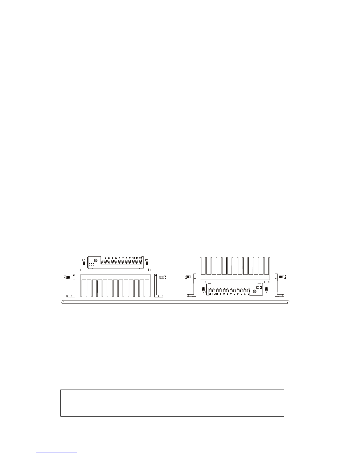
The optional HSK heat sink kit for Centent drives consists of heat sink, side rails and
screws to secure the drive and side rails. The side rails are reversible, allowing the two
mounting configurations shown in
XFigure 2X. Contact Centent Company to order the
HSK heat sink kit.
Figure 2 - HSK heat sink kit
No additional connectors are required when wiring to the Terminal Connector of the
CN0165. Either stranded or solid conductor wire may be used. A wire size of 16-22
gauge is recommended. The insulation should be stripped back 0.25 inches (7 mm) for
insertion into the terminal block. Care must be taken when tightening the screws in the
terminal block. Use a torque limiting driver if possible, to avoid damage to the
terminals.
CAUTION: DO NOT OVER-TORQUE THE TERMINAL CONNECTOR
SCREWS. MAXIMUM TORQUE ON THE TERMINALS IS 4.5 LB. - IN.
Page 8
CENTENT CN0165 MICROSTEP DRIVE
4
POWER SUPPLY INPUTS
Terminal 2 connects to the positive output from the power supply. The voltage range is
+18 to +80 VDC. The power supply may be unregulated. Limit the ripple voltage
(unregulated supplies) to a maximum of 10% of the DC output voltage. Terminal 1 is
the ground connection. Do not use Terminal 12 for power supply ground; it is the return
connection for the Current Set resistor.
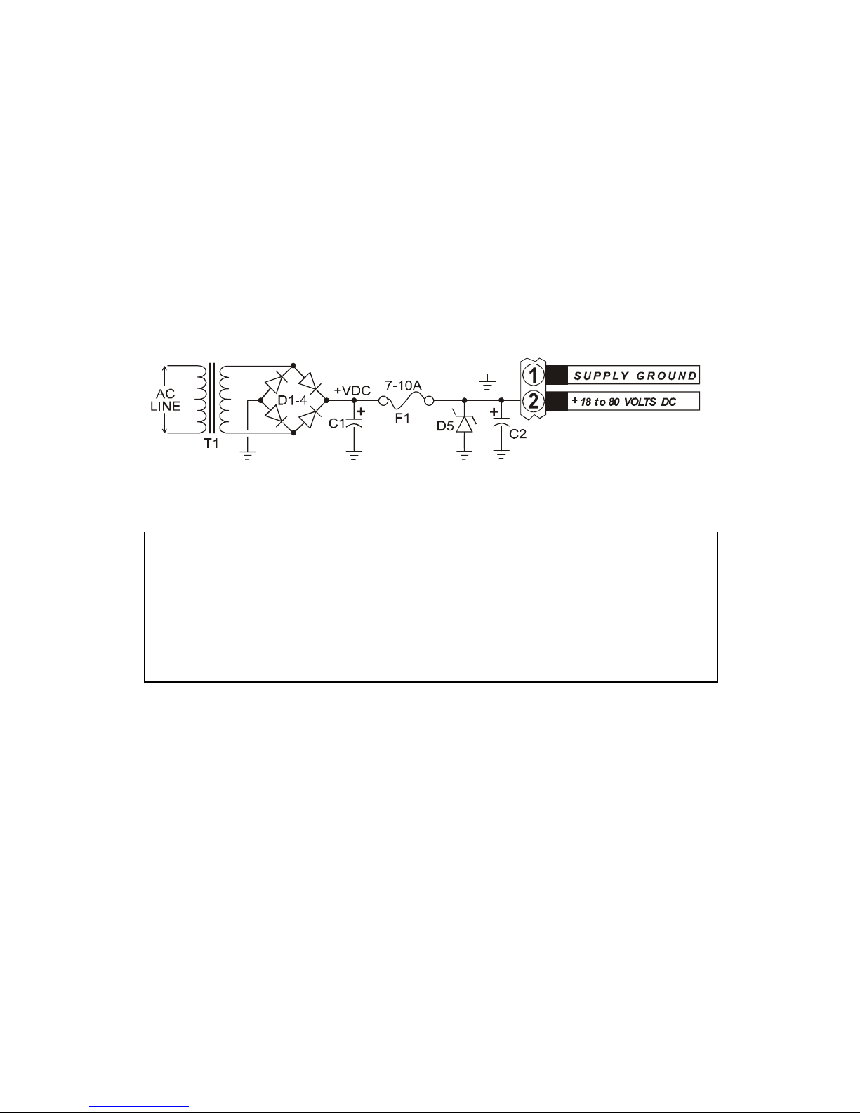
For those users that wish to build their own power supply,
XFigure 3X shows a suggested
circuit. Because of the electrical noise generated by these drives, it is not recommended
that the supply be shared with low level logic circuitry.
Figure 3 - Power Supply
The power supply terminals should have a capacitor of 470µf or greater
connected across them. This is particularly important for regulated power
supplies since they usually have little output capacitance. Locate the
capacitor as close to Terminals 1 & 2 of the CN0165 as possible (see
XFigure 3X, C2). Be sure the voltage rating for the capacitor is higher than
the drive’s supply voltage.
During rapid deceleration of large inertial loads from high speeds, step motors become
generators of considerable electrical power. This is returned to the power supply by the
step motor drive. If the supply cannot absorb this power, the voltage generated may
exceed the 80 volt limit of the CN0165, thus damaging the drive and power supply.
To protect the drive and power supply, the user may connect an external zener diode
from Terminal 2 to ground (see
XFigure 3X, D5). This diode will protect the drive from
over-voltage conditions. Recommended diodes are 1N4762 (one watt) or 1N5375 (five
watt). Note the 7-10 amp fuse (F1) placed in series with Terminal 2 and the power
supply. Be sure this fuse is located between the power supply and the zener diode. In
case of an over-voltage condition, the zener diode and fuse may be destroyed, but the
CN0165 and the power supply will be protected from damage.
The power supply current required depends on the motor being used and whether the
configuration is for parallel or series operation. See Motor Winding Configuration in
the Performance section of this manual on page
X19X for a complete explanation of motor
wiring options.
Page 9

INSTALLATION
5
Parallel operation requires a maximum of
two thirds of the motor's rated per phase
current.
Series operation requires a maximum of one
third the motor's rated per phase current.
Use the manufacturer's phase current rating for the motor and the motor wiring
configuration (high or low performance) to estimate the size of power supply required.
As an example, a six lead motor rated by the manufacturer at four amps per phase is
connected in the full winding (series) configuration. To calculate the current required
from the power supply use Equation 2. Assume a transformer with a 25 volt RMS
secondary is used. After rectification the transformer will produce a 37 VDC power
supply voltage. To calculate the size of the filter capacitor (C1) use the following
equation:
()()()
(
)
ff
V
I
C
SUPPLY
SUPPLY
μμ
300048.2995
37
33.1333,83333,83
1 ≈===
Equation 3 - Power Supply filter capacitor
C2 (XFigure 3X, page X4X) is the 470 µf capacitor located close to the CN0165’s power
supply terminals. C1 may be made smaller by that amount if desired. Both capacitors
must have a voltage rating safely in excess of the power supply voltage, 50 VDC in this
example.
More than one CN0165 may be run from a common power supply if the filter capacitor
is large enough to handle the combined load of the drives. Each CN0165 must have
separate power leads to the supply. Do not daisy-chain power leads from supply to
driver to driver.
I
SUPPLY
= 2/3 x I
PHASE
Equation 1 - Drive Current (Parallel)
I
SUPPLY
= 1/3 x I
PHASE
Equation 2 - Drive Current (Series)
Page 10
CENTENT CN0165 MICROSTEP DRIVE
6
MOTOR PHASE OUTPUTS
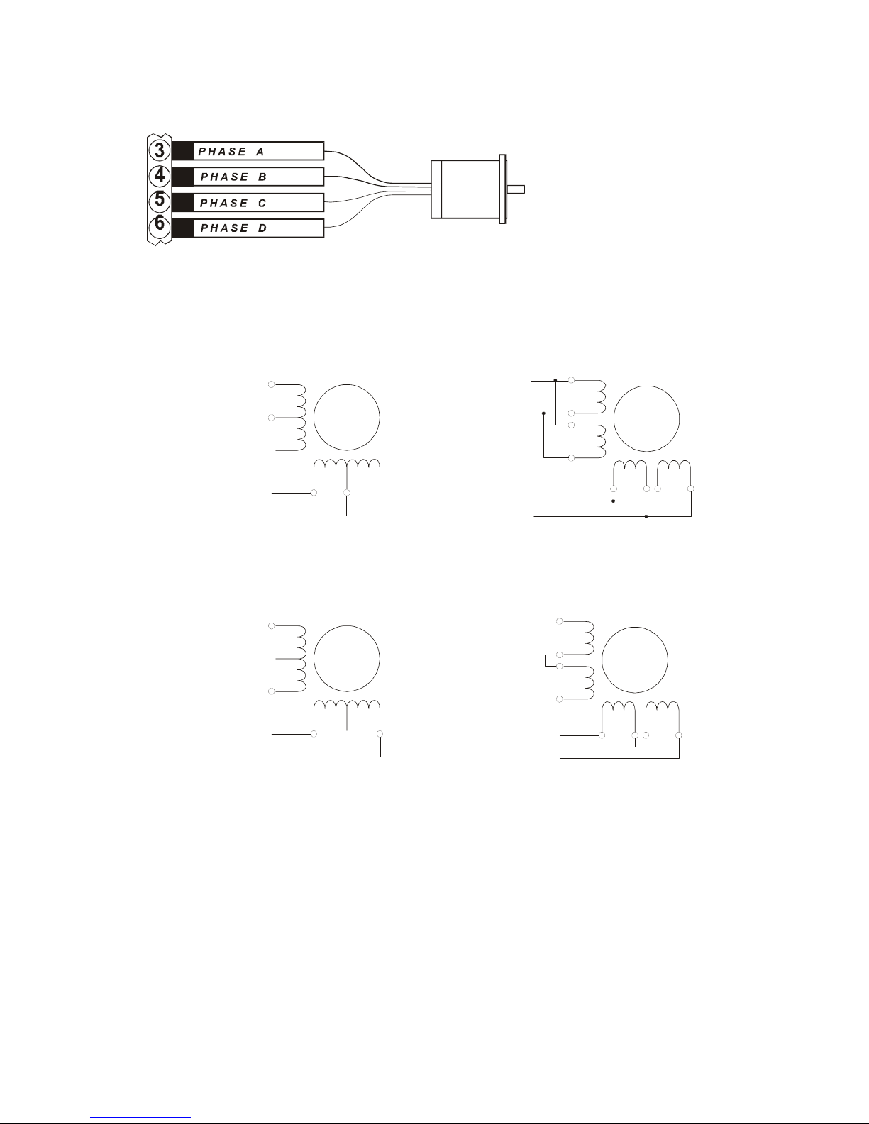
These are the drive’s
outputs to the step motor
phase windings. One motor
winding pair goes to
Terminals 3 & 4 and the
other motor winding pair
goes to Terminals 5 & 6.
The CN0165 is designed to drive four, six and eight lead step motors. With six or eight
lead motors, there are two options for connecting the motor to the drive. They are Series
and Parallel, as shown in
XFigure 4X and XFigure 5X.
Figure 4 - Parallel configuration
Figure 5 - Series configuration
Since a four lead motor has only one possible wiring configuration, consider it to be
connected in the Parallel configuration. See Motor Winding Configuration in the
Performance section of this manual (page
X19X) to determine the best wiring configuration
for the application.
The CN0165 is a high frequency switching type drive. Because of the rapid rate of
voltage and current change inherent with this type of drive, considerable RFI is
generated. The following precautions will prevent noise from coupling back to the
inputs and causing erratic operation.
n.c.
n.c.
6 LEAD
MOTOR
PHASE A
PHASE C
PHASE B
PHASE D
8 LEAD
MOTOR
PHASE A
PHASE C
PHASE B
PHASE D
n.c.
n.c.
6 LEAD
MOTOR
PHASE A
PHASE C
PHASE B
PHASE D
8 LEAD
MOTOR
PHASE A
PHASE C
PHASE B
PHASE D
Page 11

INSTALLATION
7
The Parallel configuration in a six lead motor uses the center-tap and one end to form a
winding. The other lead of each phase pair is not connected. For an eight lead motor,
the phases are connected as two pairs of parallel windings. See
Figure 4
X for details.
The Series configuration in a six lead motor uses the end leads of each phase to
constitute a winding. The center-taps are not used. For an eight lead motor the phases
are connected as a pair of series windings. See Figure 5 for details.
1. Never run the motor leads in the same cable or wiring harness as
the Step Pulse, Direction or +5 VDC input lines.
2. Keep power supply leads as short as possible. If the length exceeds
12 inches, use a 0.1 µf capacitor across Terminals 1 & 2 at the
drive.
3. Never wire capacitors, inductors or any other components to the
motor output terminals.
4. Ground the CN0165 case.
5. Ground the step motor case.
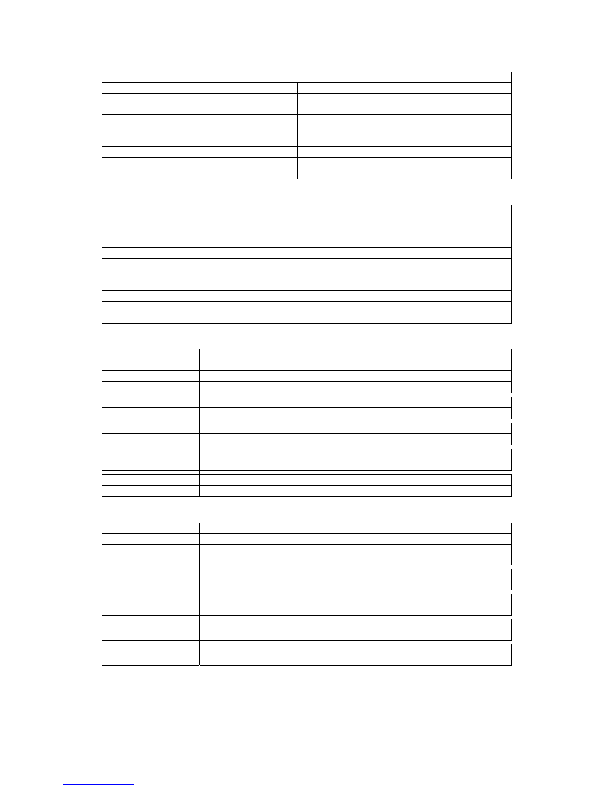
Tables 1 & 2, page
X8X, show various manufacturers’ color codes for six lead motors and
the connections to the CN0165 for half winding and full winding operation. Tables 3 &
4 show how to connect various manufacturers’ eight lead motors for series and parallel
operation.
Note that the leads connected together for series operation do not connect to a terminal
on the CN0165. These leads should not be left exposed; insulate them with electrical
tape or heat-shrink tubing.
Consult the motor manufacturer's catalog for motors not listed in tables 1 through 4.
Page 12
CENTENT CN0165 MICROSTEP DRIVE
8
CN0165 TERMINAL
MANUFACTURER 3 4 5 6
SUPERIOR ELECTRIC GREEN/WHITE GREEN RED/WHITE RED
RAPIDSYN GREEN/WHITE GREEN RED/WHITE RED
IMC GREEN/WHITE GREEN RED/WHITE RED
EASTERN AIR DEV. GREEN/WHITE GREEN RED/WHITE RED
PACIFIC SCIENTIFIC BLACK ORANGE RED YELLOW
WARNER ELECTRIC BROWN ORANGE RED YELLOW
VEXTA BLUE RED BLACK GREEN
JAPAN SERVO BLUE RED YELLOW GREEN
Table 1 - Full Winding Operation
CN0165 TERMINAL
MANUFACTURER 3 4 5 6
SUPERIOR ELECTRIC WHITE GREEN BLACK RED
RAPIDSYN WHITE GREEN BLACK RED
IMC WHITE GREEN BLACK RED
EASTERN AIR DEV. WHITE GREEN BLACK RED
PACIFIC SCIENTIFIC BLACK ORG./BLACK RED RED/YEL.
WARNER ELECTRIC BLACK ORANGE RED WHITE
VEXTA BLUE WHITE YELLOW GREEN
JAPAN SERVO BLUE
WHITE• WHITE•
GREEN
White leads are NOT interchangeable. Use ohm meter to find White-Blue & White-Green pairs.
Table 2 - Half Winding Operation
CN0165 TERMINAL
MANUFACTURER 3 4 5 6
SUPERIOR RED RED/WHITE GREEN GRN./WHT.
ELECTRIC
BLACK ∋ WHITE ORANGE ∋ BLACK/WHITE
PACIFIC BLACK ORANGE RED YELLOW
SCIENTIFIC
BLACK/WHITE ∋ ORANGE/WHITE RED/WHITE ∋ YEL./WHITE
BODINE BROWN ORANGE RED YELLOW
BRN./WHITE ∋ ORANGE/WHITE RED/WHITE ∋ YEL./WHITE
PORTESCAP BROWN ORG./WHITE RED YEL./WHITE
BROWN/WHITE ∋ ORANGE RED/WHITE ∋ YELLOW
DIGITAL MOTOR BLACK ORANGE RED YELLOW
BLACK/WHITE ∋ ORANGE/WHITE RED/WHITE ∋ YEL./WHITE
Table 3 - Series Winding Operation
CN0165 TERMINAL
MANUFACTURER 3 4 5 6
SUPERIOR
ELECTRIC
RED
WHITE
BLACK
RED/WHITE
GREEN
BLACK/WHITE
ORANGE
GRN./WHITE
PACIFIC
SCIENTIFIC
BLACK
ORANGE/WHITE
BLACK/WHITE
ORANGE
RED
YEL./WHITE
RED/WHITE
YELLOW
BODINE BROWN
ORG./WHITE
BRN./WHITE
ORANGE
RED/WHITE
YELLOW
RED
YEL./WHITE
PORTESCAP BROWN
ORANGE
BRN./WHITE
ORG./WHITE
RED
YELLOW
RED/WHITE
YEL./WHITE
DIGITAL MOTOR BLACK
ORANGE/WHITE
BLACK/WHITE
ORANGE
RED
YEL./WHITE
RED /WHITE
YELLOW
Table 4 - Parallel Winding Operation
Page 13
INSTALLATION
9
FAULT / RESET
(INPUT/OUTPUT)
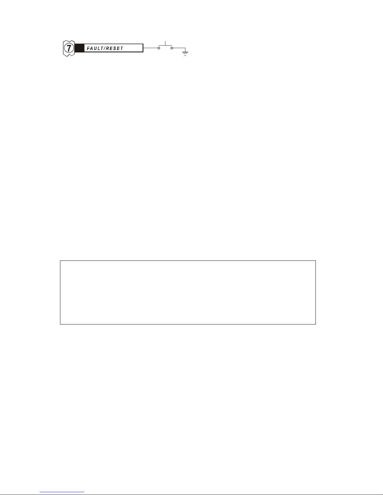
Terminal 7 is the Fault/Reset Terminal. This serves both as an output, to indicate when
a fault has occurred; and as an input, to reset the drive.
The CN0165 has protection circuitry to shut down the drive when potentially damaging
conditions exist. The state of the protection circuitry is available on the Fault/Reset
Terminal. The Fault LED (light emitting diode) provides visual indication of the fault
condition.
The Fault Output latches low and the LED stays on for either of the following fault
conditions:
• A short circuit of the motor windings (or motor lead wiring)
•
Overheating: temperature of CN0165 exceeds 70°C
A short circuit reset is distinguished from an overheating reset by observing the case
temperature of the CN0165. A short-circuit reset will shut down the drive before it
reaches a high temperature. If the case temperature is low immediately after a reset
occurs, the cause is a short circuit.
Do not continue to operate the CN0165 if it is resetting due to overheating. Heat sinking
must be provided to prevent the drive from repeatedly entering thermal shutdown.
The Fault Output goes low (LED on), but does not latch, if the power supply voltage
drops below 18 volts DC. When no fault condition exists, the Fault Output is pulled up
to 12 volts DC by an internal 470 ohm resistor and the LED is turned off. The Fault
Output is capable of sinking up to 20 milliamps of current.
While the Fault Output is low, the internal counters reset to microstep zero and the
phase outputs are held low. The CN0165 ceases all switching activity and the motor
phase current goes to zero. A latched fault condition is cleared by a Reset (take
Terminal 7 to ground) or by recycling the power supply to the drive (power off, power
on).
Terminal 7 also functions as a Reset input. By taking the Fault/Reset Terminal to
ground, the motor phase currents are shut off and the internal counters are reset. When
Terminal 7 is released from ground the motor is located at microstep zero. A current of
20 milliamps will flow from the Fault/Reset Terminal when it is shorted to ground.
THE PROTECTION PROVIDED BY THE INTERNAL TEMPERATURE
SENSOR OF THE CN0165 IS NOT A SUBSTITUTE FOR ADEQUATE
HEAT SINKING. REPEATEDLY TRIPPING THE FAULT OUTPUT BY
ALLOWING THE DRIVE TO OVERHEAT CAUSES THERMAL STRESS
THAT WILL EVENTUALLY LEAD TO FAILURE OF THE DRIVE.
Page 14
CENTENT CN0165 MICROSTEP DRIVE
10
DIRECTION INPUT
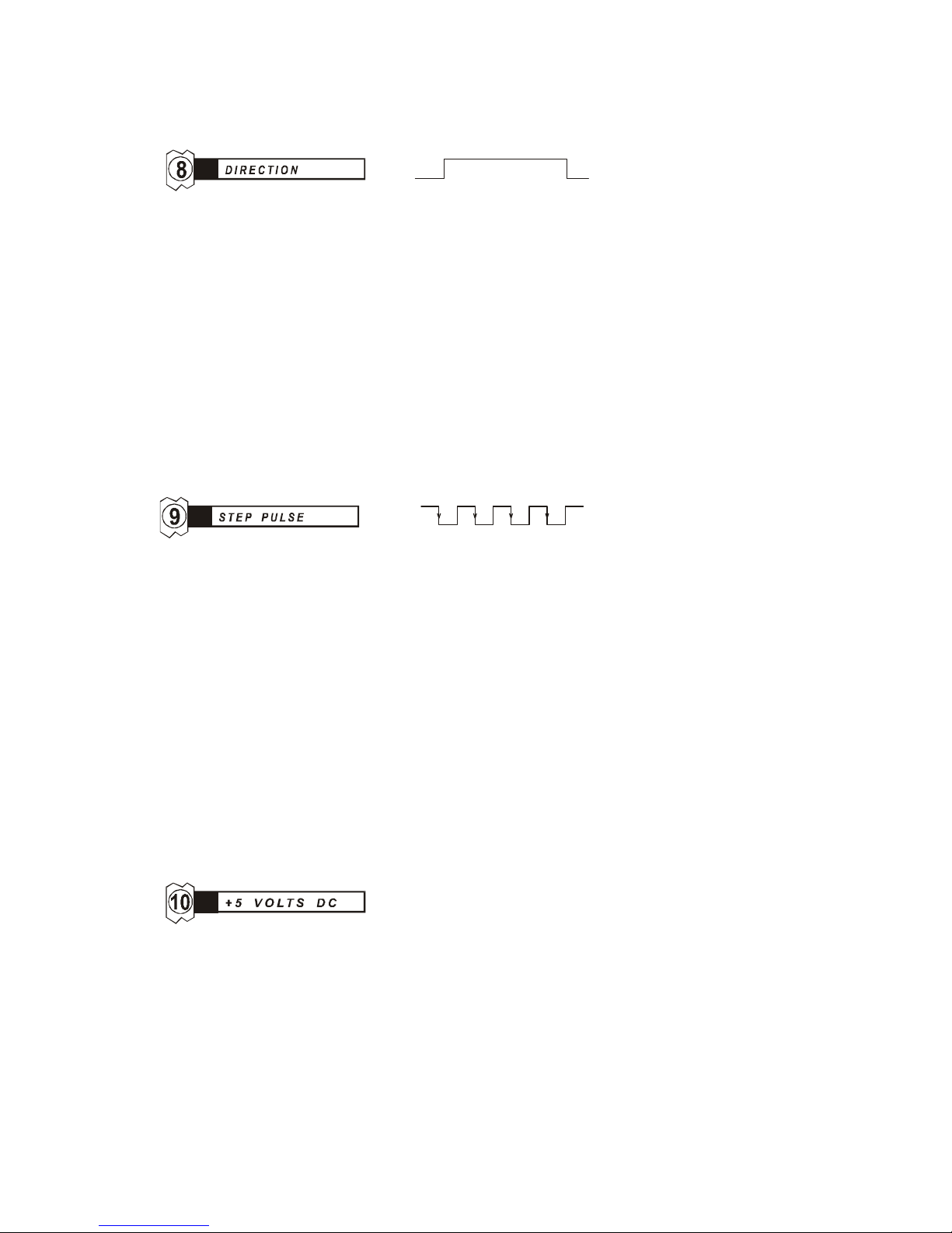
Terminal 8 is the Direction Input. This input is sampled by the CN0165 on every step
pulse input to determine which direction the step motor will move.
The state of the Direction Input must be held one microsecond after the active edge of
the Step Pulse Input to insure correct direction. The Direction Input can be updated
simultaneously with the active (high to low) transition of the Step Pulse Input.
The CN0165 uses a high speed opto-isolator for the Direction Input. The purpose of the
opto-isolator is to isolate the Direction Input from the driver's power supply. The user
must provide a +5 VDC supply to operate the opto-isolator. This permits the use of
current sink drivers, such as TTL logic or open collector transistors, to operate the
input. The minimum current required to operate the opto-isolator is 3.5 milliamps.
STEP PULSE INPUT
Microstepping in the CN0165 occurs on the high to low transition of the step pulse
input.
The CN0165 employs a high speed opto-isolator to isolate the Step Pulse Input from the
driver's power supply. The user must provide a +5 VDC supply (shared with the
Direction Input) to operate the opto-isolator circuitry. This permits the use of current
sink drivers, such as TTL logic or open collector transistors, to operate the input.
The minimum current required to operate the opto-isolator is 5 milliamps. The
maximum Step Pulse rate is 1.5 MHz. The minimum on or off time is 50 nanoseconds.
+5 VDC INPUT
This input is connected internally to the anodes of the Step Pulse and the Direction
opto-isolator LEDs. The external +5 VDC supply provides the source of LED current
for the Step Pulse and Direction inputs. A minimum of 10 mA is required (Step and
Direction both 'on' @ 5 mA per opto-isolator).
Power supply voltages higher than 5 VDC may be used for this input. Both the Step
Pulse and the Direction Input will require external resistors to limit the current to the
opto-isolators if the operating voltage is higher than five volts. The following equation
determines the value for these resistors and limits the supply current to the opto-isolator
LEDs to approximately five milliamps.
Page 15
INSTALLATION
11
01.
)5(R−
=
V
Equation 4 - External Opto-isolator resistor
For example, if a +12 volt supply is to be used:
Ω≈=
−
= 680007
.01
)5(12
R
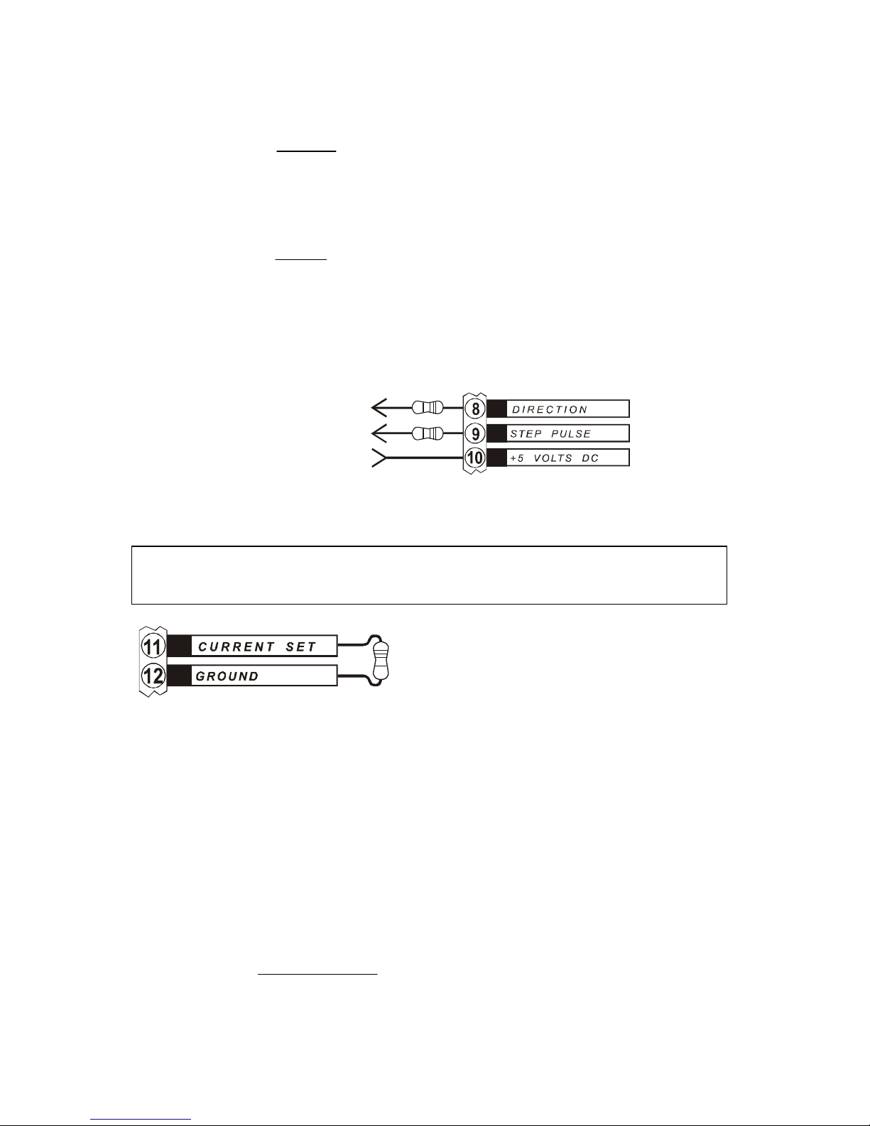
Place 680 ohm resistors between Terminal 8 and the Direction source and between
Terminal 9 and the Step Pulse source.
to direction source
to step pulse source
from power source
Figure 6 - External Opto-isolator resistors
IMPORTANT: DO NOT PUT A RESISTOR IN SERIES WITH THE +5 VDC TERMINAL.
CURRENT SET
The Current Set Input determines the magnitude of the motor phase currents. This is
done by connecting a
¼ watt resistor between terminals 11 & 12. Terminal 11 is the
Current Set Input and Terminal 12 is the ground reference.
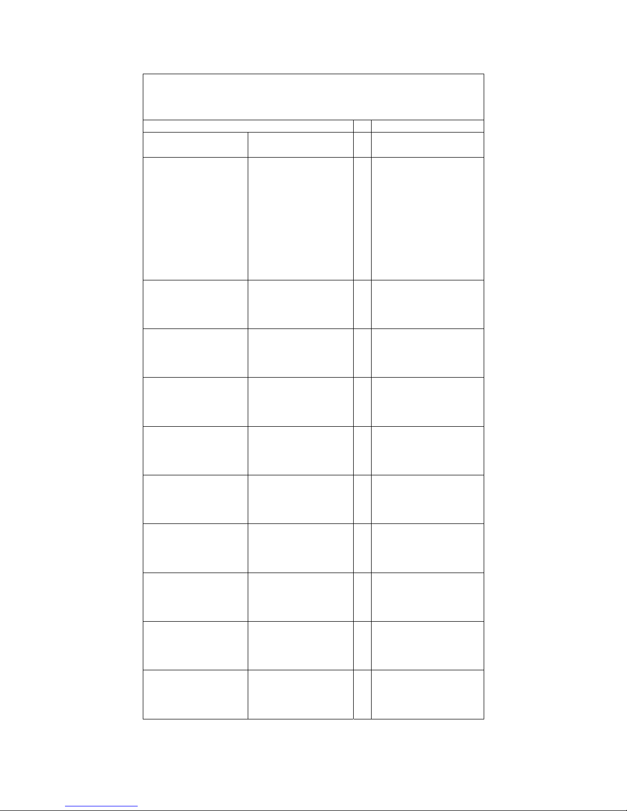
Table 5, page
X13X, lists resistors to the nearest 5% standard value, for both parallel (half
winding) and series (full winding) operation. An abbreviated table is printed on the case
of the CN0165 for user convenience. Use the parallel values for operating four lead
motors.
The resistor values in Table 5 and on the case of the CN0165 are derived by using the
following equation:
SET
SET
SET
I
I
R
−
=
10
))(47000(
Where:
R
SET =
current set resistor
I
SET =
desired current.
Equation 5 - Current Set resistor
Page 16

CENTENT CN0165 MICROSTEP DRIVE
12
Zero operating current is obtained by shorting terminals 11 & 12 together.
The maximum phase current of 10 amps is obtained with no resistor installed across the
terminals. Be sure the motor is large enough, and the drive heat sinking is adequate to
handle the current if Terminal 11 is left unconnected.
For best low speed smoothness, the motor phase current should not differ from the
manufacturer's suggested phase current rating by more than ± 20%. Currents above or
below this level may affect microstep accuracy and increase low speed vibration.
The Current Set Input is used in conjunction with the Standby Current Trimpot (see
page
X15X) to set the current levels for active (motor moving) and standby (motor idle)
conditions.
The Current Set Input may also be driven by external circuitry such as an operational
amplifier or a digital to analog converter from a programmable controller.
Motor phase current is a linear function of the voltage on Terminal 11. The voltage
applied to Terminal 11 should range from zero (phase current = zero amps) to 2.5 volts
(phase current = 10 amps). Do not apply voltages higher than 2.5 volts to Terminal 11
as it may result in permanent damage to the drive.
DO NOT USE TERMINAL 12 FOR POWER SUPPLY GROUND.
TERMINAL 12 IS FOR CURRENT REFERENCE ONLY.
TERMINAL 1 IS THE POWER SUPPLY GROUND.
Page 17
INSTALLATION
13
CURRENT SET TABLE
MODE OF OPERATION RESISTOR
HALF WINDING
(PARALLEL)
FULL WINDING
(SERIES)
STANDARD ±5%
(OHMS)
0.1 A
0.2 A
0.3 A
0.4 A
0.5 A
0.6 A
0.7 A
0.8 A
0.9 A
1.0 A
0.2 A
0.4 A
0.6 A
0.8 A
1.0 A
1.2 A
1.4 A
1.6 A
1.8 A
2.0 A
470Ω
1.0 K
1.5 K
2.0 K
2.4 K
3.0 K
3.6 K
3.9 K
4.7 K
5.1 K
1.25A
1.50 A
1.75 A
2.00 A
2.50 A
3.00 A
3.50 A
4.00 A
6.8 K
8.2 K
10 K
12 K
2.25A
2.50 A
2.75 A
3.00 A
4.50 A
5.00 A
5.50 A
6.00 A
13 K
16 K
18 K
20 K
3.25A
3.50 A
3.75 A
4.00 A
6.50 A
7.00 A
7.50 A
8.00 A
22 K
24 K
27 K
30 K
4.25A
4.50 A
4.75 A
5.00 A
8.50 A
9.00 A
9.50 A
10.00 A
36 K
39 K
43 K
47 K
5.25A
5.50 A
5.75 A
6.00 A
10.50 A
11.00 A
11.50 A
12.00 A
51 K
56 K
62 K
68 K
6.25A
6.50 A
6.75 A
7.00 A
12.50 A
13.00 A
13.50 A
14.00 A
75 K
91 K
100 K
110 K
7.25A
7.50 A
7.75 A
8.00 A
14.50 A
15.00 A
15.50 A
16.00 A
120 K
150 K
160 K
180 K
8.25A
8.50 A
8.75 A
9.00 A
16.50 A
17.00 A
17.50 A
18.00 A
220 K
270 K
330 K
430 K
9.25A
9.50 A
9.75 A
10.00 A
18.50 A
19.00 A
19.50 A
20.00 A
560 K
910 K
1.8 M
OPEN
Table 5 - Current Set
Page 18
CENTENT CN0165 MICROSTEP DRIVE
14
OPTION HEADER: RESOLUTION SELECTION
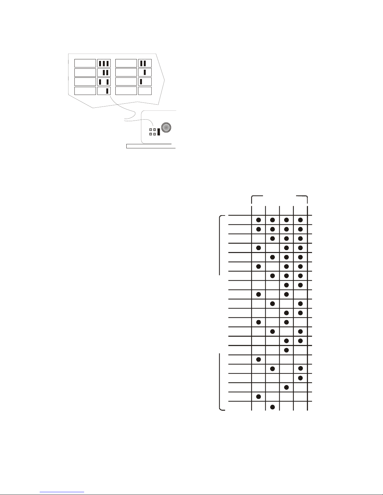
The Option Header selects a microstep
resolution from the eight available in the drive.
The header is located on the face of the drive,
next to the Fault LED.
The jumper configuration for each of the eight
selections is printed on the cover of the
CN0165 adjacent to the Option Header. The
step rate for each selection is shown. To select
a resolution, install the jumper(s) as indicated
for the desired microstep.
Figure 7 - Resolution Header
There are twenty-one different microstep
resolutions available in the CN0165. The
drive is supplied to the user with up to eight
of the twenty-one available. Not all
combinations of step resolutions are possible.
All eight step resolutions for a given CN0165
must come from a single option column (A,
B, C or D) of
XTable 6X.
It is permissible to switch the Option Header
selection dynamically. To accomplish this
the shorting bars are replaced with TTL
compatible drivers. No damage will occur if
the microstep resolution or current profile is
changed while the motor is running.
Switching must occur at the full step location
to maintain accurate step position.
As well as choosing between microstep
resolutions, the Option Header may be used
to select different phase current profiles. Any
combination of microstep resolutions and
phase current profiles may be specified,
provided all step resolutions come from the
same column of
XTable 6X. For more
information on current profiles, see Current
Profile Option on page
X25X.
Table 6 - Resolution options
125
250
5
125
10
CONFIGURED FOR
10 MICROSTEPS
IN THIS EXAMPLE
250
256
250
200
160
128
125
100
80
64
50
40
32
25
20
16
10
8
5
4
half
full
ABCD
STEP RESOLUTION
OPTION
Page 19
INSTALLATION
15
STANDBY CURRENT TRIMPOT
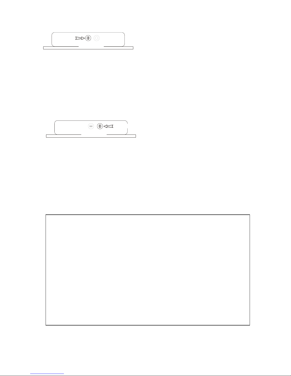
The Standby Trimpot sets the current level of the CN0165 when the motor is not
stepping. Turning the potentiometer to the full clockwise position disables Current
Standby. The full counter-clockwise position results in 100% Current Standby
(freewheeling). The halfway position (screwdriver slot vertical) results in a Standby
current of 50% of operating current. Current Standby becomes active one second after
the last step pulse is received. Motor phase current is restored to its normal level two
milliseconds after the first step pulse in the next motor move is received.
OFFSET TRIMPOT
The offset trimpot provides compensation for the distortion that occurs to microstep size
near the half-step location. Residual full step cyclic errors, a function of power supply
voltage, motor phase inductance and phase current magnitude, can cause an uneven
microstep size. These errors can be compensated by adjusting the Offset Trimpot.
The magnitude of the untrimmed error is on the order of one sixteenth of a full step, so it
is unlikely to be noticeable at resolutions less than 16 microsteps. Trimming is certainly
unnecessary at resolutions below 10 microsteps. Compensation is disabled at the
half-scale position (screwdriver slot vertical) of the trimpot.
To adjust the CN0165 for optimum microstep compensation:
1. Disable the microstep compensation by positioning the screwdriver slot of the
Offset Trimpot vertical.
2. Connect the motor and power supply to the CN0165.
3. Connect a pulse source to the Step Pulse Input and set to 2-3 full steps/sec.
(a function generator set to
±
5 volt levels is suitable for this purpose)
4. Apply power to the motor and drive.
5. Adjust the Offset Trimpot for minimum vibration by turning clockwise or
counter-clockwise.
ST AND B Y
(REAR VIEW)
(REAR VIEW)
OFFSET
Page 20

CENTENT CN0165 MICROSTEP DRIVE
16
FAULT LED
The CN0165 has protection circuitry to shut down the drive when potentially damaging
conditions exist. The state of the protection circuit is available on the Fault LED as well
as the Fault/Reset Terminal. See Fault/Reset, Terminal 7, on page
X9X for details on fault
conditions.
POWER ON RESET
The Power-on Reset circuitry of the CN0165 insures that the drive turns on in an
organized manner. The motor phase outputs are held low (ground) and the internal
counters are held to microstep zero until the power supply voltage rises to the minimum
operating voltage level of the drive.
The minimum voltage for operation is 18 VDC. Power-on Reset releases when the power
supply voltage reaches this voltage threshold. The motor phase outputs become active,
carrying a 20 kHz signal equal in voltage to that of the power supply. The drive is now
ready to receive step pulses.
UNDER-VOLTAGE LOCKOUT
Under-voltage Lockout protects the CN0165's output transistors from damage resulting
from low power supply voltage. This feature activates when the power supply voltage
drops below 18 volts. Below this voltage, the Phase outputs (Terminals 3, 4, 5 & 6) are
pulled low. Supply current is removed from the output transistors and the motor stops
positioning. When the power supply voltage falls below five volts, the Phase outputs go
to an open circuit (floating) condition.
While the CN0165 remains in an under-voltage condition, the drive is held in the reset
state. Once the power supply voltage rises above 18 volts and all internal voltages have
stabilized to their proper levels, the Power-on Reset is automatically executed.
MICROSTEPPING
Microstepping is a technique that electronically multiplies the number of steps a motor
takes per revolution. This is useful because it increases motor angular resolution and
decreases motor vibration. A 200 step per revolution motor, operated at 100 microstep
resolution, will take 20,000 microsteps to complete one revolution of the motor shaft.
Microstepping is normally accomplished by driving the motor windings with sine and
cosine weighted currents. A 90° electrical angle change in these currents results in a
mechanical angle movement of 1.8° (full step) in a 200 step-per-revolution motor. The
sine-cosine values may be replaced with values compensated for a specific motor type or
characteristics. See Current Profile Option, page
X25X, for further information on
compensated current profiles.
Low speed vibration is the result of the start-stop pulsing motion of the motor. This
incremental input generates periodic acceleration and deceleration reaction torque at the
Page 21
PERFORMANCE
17
given step rate. When the step rate matches, or is a sub-harmonic of the mechanical
resonant frequency of the motor, the vibrations become severe.
Microstepping divides full step positioning into 'microsteps'; decreasing the magnitude of
the reaction torque generated. This results in a decrease in resonant vibration.
Another benefit of microstepping is an increase in the number of resolvable angular
positions. However, there are a number of factors that limit the achievable open-loop
accuracy of these positions. See the topics under Accuracy, beginning on page
X23X for
further details.
ANTI-RESONANCE
Most step motors are prone to parametric instability or resonance when rotating at a rate
of 4 to 15 revolutions (800 to 3000 full steps) per second. The CN0165 incorporates a
mid-band anti-resonance compensation circuit to close the loop on this instability and
damp it out electronically.
Called mid-band instability or resonance, this phenomenon appears as a torsional
oscillation of 50 to 150 Hz while the motor is running in this speed range. The torsional
oscillation has a tendency to increase in amplitude with time until it reaches a peak equal
to the step angle of the motor. When this happens, the motor loses synchronization and
stalls.
Generally, the amplitude buildup takes from tens of cycles to hundreds of cycles to reach
this level. Several seconds may elapse from the start of the oscillation until the motor
actually stalls. Usually this is long enough to allow the motor to accelerate through this
region. Continuous operation in this speed band is impossible.
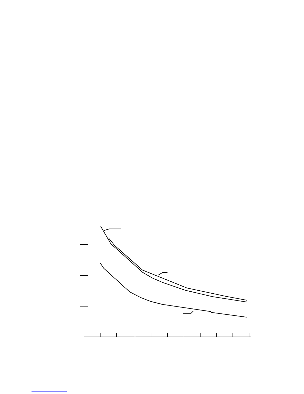
SUPERIOR M062-FD04
RAPIDSYN 34D-9208A
SIGMA 20-2350-28175
0
50Hz
100Hz
150Hz
5KHZ 10KHz
1.8 DEGREE STEP RA T E
RESONANT FREQUENCY
Figure 8 - Resonance
Page 22

CENTENT CN0165 MICROSTEP DRIVE
18
Above and below this range of speeds, the oscillation amplitude may not be sufficient to
stall the motor but it is still present. The graph in
XFigure 8X shows the parametric
resonance frequency versus motor step rate for three different step motors. In all three
cases resonance breaks out at 1000-1400 (full) steps per second and is most severe at the
higher torsional frequencies (lowest step rates).
Because any torsional oscillation implies the acceleration and deceleration of a mass,
torque that otherwise would have been available for useful work is wasted to sustain this
oscillation. The CN0165’s anti-resonance compensation circuit closes the loop on this
instability and dampens it out electronically. Since the motor will not sustain oscillation,
torque previously wasted is now available to the application.
With anti-resonance circuitry the motor may be run continuously at speeds where
de-synchronization would otherwise occur. The motor no longer exhibits 'forbidden'
regions where continuous-operation cannot be sustained. Moreover, there is more torque
available over the entire operating range of the drive.
The operation of the anti-resonance circuit is transparent to the user; no special
provisions have to be taken to accommodate it.
TORQUE AND POWER
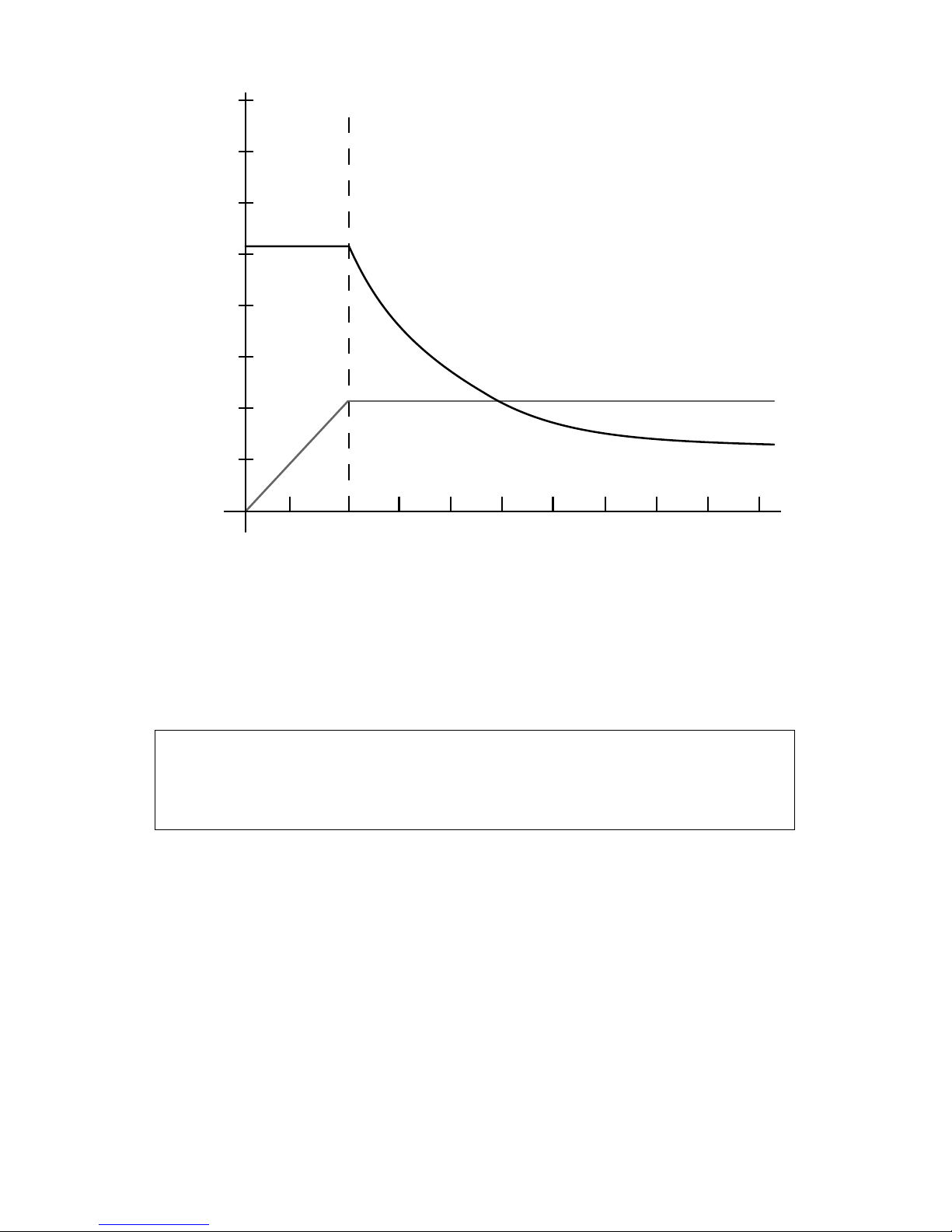
Step motor performance curves exhibit two distinct regions with respect to speed, as
shown in
XFigure 9X, page X19X. In Region 1, from 0-2000 full steps/second, motor torque is
constant with speed while motor shaft power is proportional to speed. In Region 2, from
2000 full steps/second to maximum speed, motor torque decreases as the inverse of the
speed while motor shaft power remains constant.
The value of the current set resistor determines motor torque in Region 1. Motor torque is
held constant by controlling the magnitude of the motor phase current. The step rate in
Region 1 is low enough to permit motor phase current to reach the desired value. In
Region 1 motor torque is nearly proportional to motor current and remains constant.
In Region 2 torque is no longer dependent on the value of the current set resistor. As the
motor enters Region 2, torque begins to drop off as the inverse of the speed. Motor
winding inductance limits the rate of current rise, and as speed increases, progressively
less current can be forced into the windings. Because motor torque is proportional to
phase current, and current (in Region 2) is proportional to the step period, torque
decreases as the inverse of the step rate. Torque in Region 2 may be approximated with
the equation:
T
kV
f
L
=
where: T = torque
k = motor constant
V = power supply voltage
f = steps per second
L = motor inductance
Equation 6 - Motor torque
Page 23
PERFORMANCE
19
0
1K 2K 3K 4K 5K 6K 7K 8K 9K 10K
50
100
150
200
250
300
350
400
REGION 1 REGION 2
TORQUE
POWER
FULL STEPS PER SECON D
TORQUE
(OZ/IN)
POWER
(WATTS)
Figure 9 - Torque & Power vs. Speed
Power is the product of speed and torque. Power remains constant in Region 2 in an ideal
step motor. In a real step motor there are speed related power losses (e.g., friction,
magnetic losses, windage) that result in a slope to the power curve. The intersection of
this slope and the speed axis determines the maximum speed of the motor.
THE CENTENT CN0165 DRIVE IS CAPABLE OF RUNNING STEP
MOTORS AT SPEEDS HIGH ENOUGH TO CAUSE DAMAGE TO
MOTOR SHAFT BEARINGS.
MOTOR WINDING CONFIGURATION
The customer has the option with six or eight lead motors of connecting the windings in
parallel or series configuration. For six lead motors, the series and parallel configurations
are also referred to as “full winding” and “half winding” respectively. Since there are no
configuration options for a four lead motor, it is considered to be in the parallel
configuration.
Parallel operation has twice the maximum motor power output of serial operation. The
speed to which constant torque is maintained is also doubled. This performance comes at
the expense of greater motor and drive heating. The performance of a six lead motor will
match that of an eight lead motor in the same winding configuration, assuming the
current ratings of the motors are the same.
Page 24

CENTENT CN0165 MICROSTEP DRIVE
20
If a motor is used in the series configuration, the supply current will not exceed one third
of the motor's rated per phase current. The current draw of a motor in the parallel
configuration will not exceed two thirds of the motor's per phase current rating.
Motor torque is approximately proportional to motor current multiplied by the number of
winding turns that carry the current. In series operation, twice the number of turns carry
current as in parallel operation; thus only half the current is needed to generate a given
level of torque. Unfortunately, series operation also quadruples the effective winding
inductance. In Region 2 (see
XFigure 9X, page X19X) motor power is proportional to the
inverse of the square root of the winding inductance.
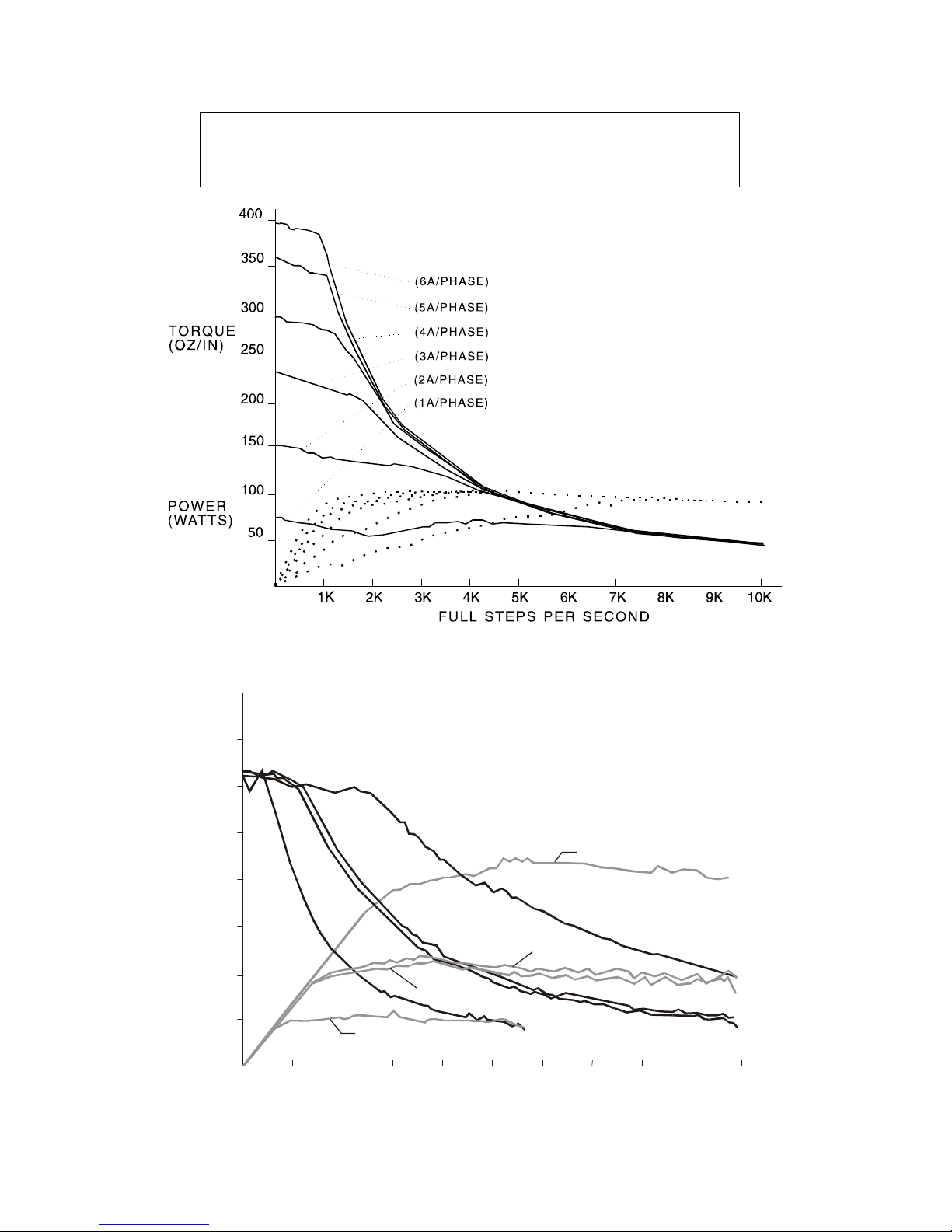
The effect of various winding currents on motor performance is illustrated in
XFigure 10X,
page
X21X. The data was acquired using a four amp per phase motor, driven from one to six
amps in one amp increments.
Note that when the motor in
XFigure 10X is operated in excess of 4000 steps per second, the
current set resistor value makes no difference in performance. What is significant is the
reduction in low speed heating of the motor and drive evident at the lower current
setting.
The effect of series versus parallel operation at low and high power supply voltages is
illustrated in Figure 11, page
X21X. Note that series operation at 54 VDC yields
performance virtually identical to parallel operation at 27 VDC.
Series configuration is preferred for Region 1 operation, and is suitable for Region 2 if
the power available is sufficient. The benefits are lower motor and drive heating and
lower power supply current requirements. For series operation the phase current level of
the CN0165 is set to one-half the motor's nameplate phase current rating.
The parallel configuration doubles high speed torque. Motor phase currents are twice
those in a series connected motor. This doubles power supply requirements and thus
results in higher motor and drive temperatures. For parallel operation the phase current
level of the CN0165 is set to the motor's nameplate phase current rating.
Page 25
PERFORMANCE
21
Holding torque and low speed torque are the same
in parallel and series configurations.
Figure 10 - Winding current vs. Torque
200
175
150
125
100
75
50
25
10K
1K 2K 3K
4K
5K 6K 7K 8K 9K
FULL STEPS PER SECOND
TORQU E
(OZ/IN)
POWER
(WATTS)
P4 (105W)
P1 (25W)
P3 (50W)
P2 (53W)
T1 T2 T3
T4
T1,P1 = 27 volts, full-winding
T2,P2 = 54 volts, full-winding
T3,P3 = 27 volts, half-winding
T4,P4 = 54 volts, half-winding
Figure 11 - Parallel vs. Series operation
Page 26

CENTENT CN0165 MICROSTEP DRIVE
22
POWER SUPPLY VOLTAGE
The CN0165 step motor drive has a power supply range from 18 to 80 VDC. The
magnitude of the power supply voltage affects the power a step motor generates in
Region 2. See
XFigure 9 - Torque & Power vs. SpeedX on page X19X. The speed to which
constant torque is maintained is proportional to power supply voltage. Consequently,
maximum motor power is also proportional to the power supply voltage.
Increasing power supply voltage increases motor heating. Considering this, the power
supply voltage should be just high enough to meet the application's power requirements
and no higher. Excessively high supply voltage will result in unwanted motor and drive
heating. To prevent damage to the drive or motor the power supply voltage must not
exceed twenty-five times (25:1) the motor's nameplate voltage rating.
POWER SUPPLY CURRENT
Power supply current is determined by the load applied to the motor, the speed the motor
is running and the value of the current set resistor. The power supply current for a series
configured motor will not exceed one third of the rated per phase current of the motor. A
parallel configured motor will require no more than two thirds of
the rated per phase
current.
The power supply current for a two amp per phase motor in the parallel configuration is
shown in
XFigure 12X. The solid line curve represents fully loaded motor operation. The
dotted line curve represents the motor during unloaded operation.
Figure 12 - Power supply current
Page 27

PERFORMANCE
23
MOTOR AND DRIVE HEATING
Motor and drive heating is equivalent to the difference between the electrical power input
to the system and the motor's mechanical power output. The ratio of output to input
power defines the system efficiency. The power losses that lower efficiency are
dependent on motor speed, load and winding configuration, the power supply voltage,
current set value, drive losses and other factors. The power losses in the drive are
primarily resistive and easy to calculate. Each channel of the drive is equivalent to a 0.55
ohm resistor.
Motor drive current dissipation in Region 1 (
XFigure 9X, page X19X) is always considerably
higher than in Region 2. In Region 1, motor phase currents, and therefore drive channel
currents are sinusoidal. The peak amplitude is equal to the rated per phase current for
parallel operation and half of that for serial operation. In Region 1, power dissipation
may be calculated as follows.
R1
Parallel
:
(
)
2
55.0
φω
I=
Equation 7 - Region 1 Current dissipation,
Parallel operation
R1
Series
:
2
2
55.0
⎟
⎠
⎞
⎜
⎝
⎛
=
φ
ω
I
Equation 8 - Region 1 Current dissipation,
Series operation
Note that the power dissipation is four times higher for the parallel configuration. In
Region 2 power dissipation may be calculated as follows.
R2
Parallel
:
2
3
55.0
⎟
⎠
⎞
⎜
⎝
⎛
=
φ
ω
I
Equation 9 - Region 2 Current dissipation,
Parallel operation
R2
Series
:
2
6
55.0
⎟
⎠
⎞
⎜
⎝
⎛
=
φ
ω
I
Equation 10 - Region 2 Current dissipation,
Series operation
Region 1 power dissipation is 4.5 times greater than Region 2 power dissipation. If the
motor will spend most of its time stopped or in Region 1, use Region 1 power dissipation
equations to determine the size of the heat sink. Utilizing the Standby Current Trimpot to
lower power dissipation while the motor is idle will minimize heat sink requirements.
MOTOR TOLERANCES
Most step motors are specified as having a ±5 percent non-accumulative step tolerance.
This implies that a 200 step per revolution motor will have an absolute accuracy of one
part out of 2000. If the motor is run open loop (as most step motors are), the user cannot
expect to position a motor accurately at anything greater than a 10 microstep resolution.
Using a higher microstep resolution, in an open-loop application, will contribute to motor
smoothness but will not increase resolution.
Page 28
CENTENT CN0165 MICROSTEP DRIVE
24
MOTOR LOAD
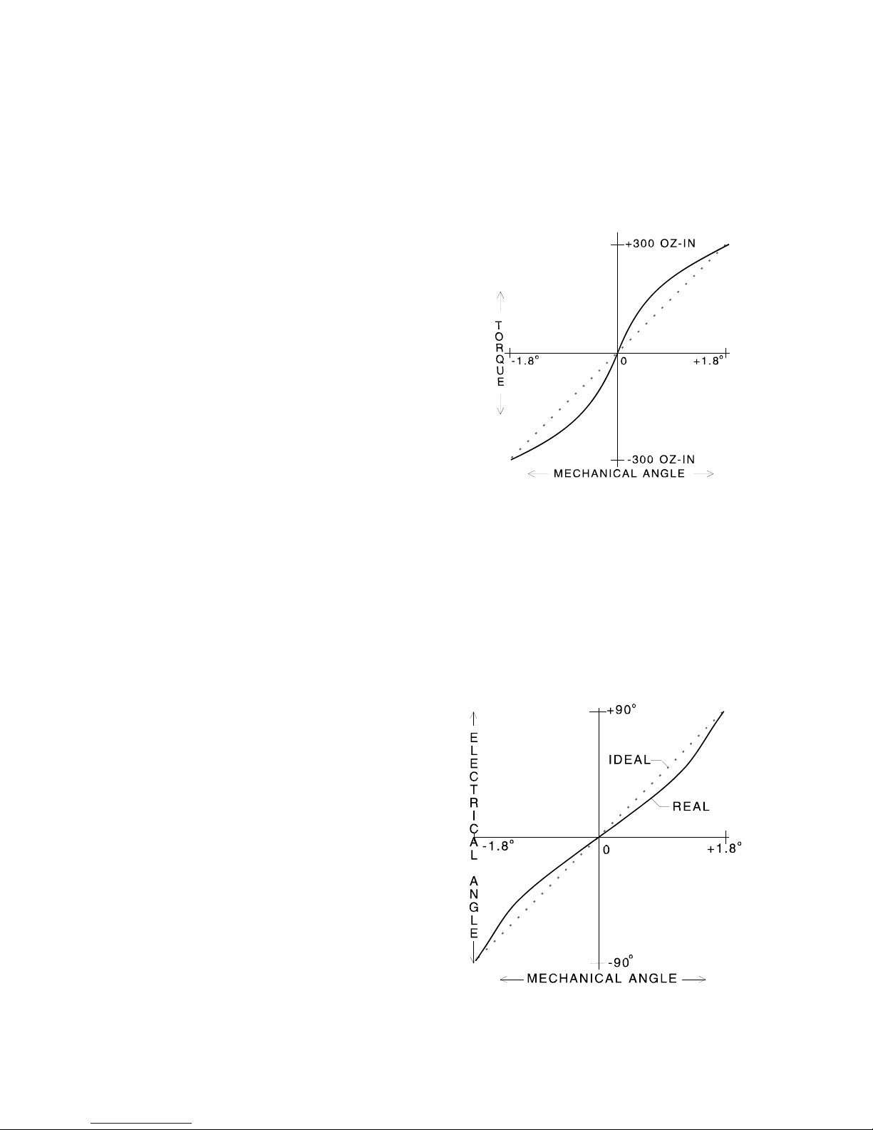
Motor load is the most significant contributor to microstep positioning error. A step
motor only generates torque when an error angle in rotor position exists. The relationship
between rotor displacement angle and restoring torque for a typical motor is shown in
XFigure 13X.
The function that relates error angle to torque
is approximately sinusoidal. An error angle
equal to one microstep occurs when the
motor load equals the holding torque divided
by the microstep resolution.
If the motor load is transient, the rotor error
will decrease to a residual level upon
removal of the transient load. This applies to
the load induced by the acceleration and
deceleration of the step motor during the
course of a normal move.
Figure 13 - Torque vs. rotor angle
MOTOR LINEARITY
Motor linearity is the relationship between the mechanical angle of shaft rotation and the
electrical angle of the winding currents. In an ideal motor this is directly proportional; the
application of sine-cosine currents produces uniform shaft rotation and equally spaced
microsteps.
Real motors exhibit distortion as represented
in
XFigure 14 - Motor linearityX. Varying the
value of the current set resistor may help trim
the error.
Should this method be inadequate, the motor
winding currents may be distorted to
compensate for the non-linearity. Centent can
provide a 3rd Harmonic profile or generate a
compensated profile for motors of a like
model number or type. These custom profiles
are 'programmed' into the customer's CN0165
as a Current Profile Option, as described in
the next section.
Figure 14 - Motor linearity
Page 29

ACCURACY
25
CURRENT PROFILE OPTION
The options described in this section apply to a very small percentage of applications and
should not be specified unless required. The standard Sine-Cosine profile will provide
the best performance for most motors and applications.
The non-linear microstep size of a step motor can be offset by distorting the current
profile to compensate for the mechanical characteristics of the motor. Two options are
offered for step motors that cannot be adequately compensated or applications requiring
exceptional smoothness.
The first option is the 3rd Harmonic profile. This provides improvement for step motor
designs that exhibit distortions that are 3rd harmonic in nature. Centent Company will
assist in evaluating a motor for this option.
The second option is the Compensated Current Profile. A specific model of step motor is
run on a dynamometer to empirically generate the current profile necessary for even
microstep size. This provides maximum smoothness and accuracy but will not work well
with another model of step motor.
The CN0165 may be ordered with different current profiles in the same drive. The eight
selections (see Option Header, page
X14X) may be any combination of current profiles and
step resolutions, provided the step resolutions are all selected from the same column of
the Resolution Options Table on page
X14X.
MOTOR SPEED-TORQUE CURVES
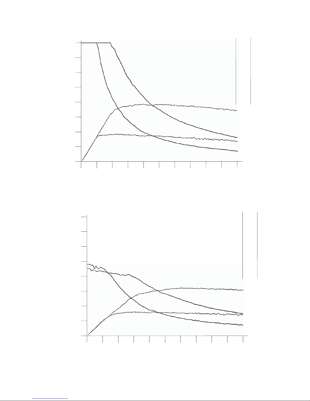
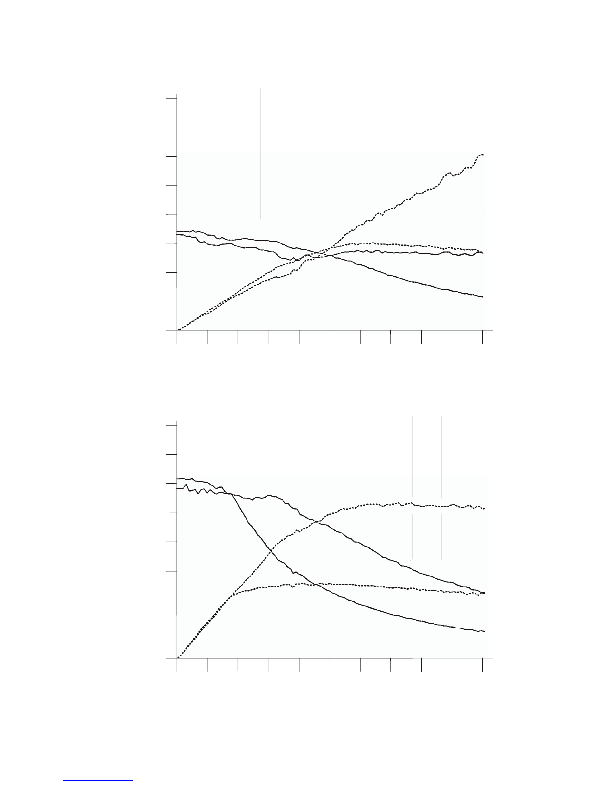
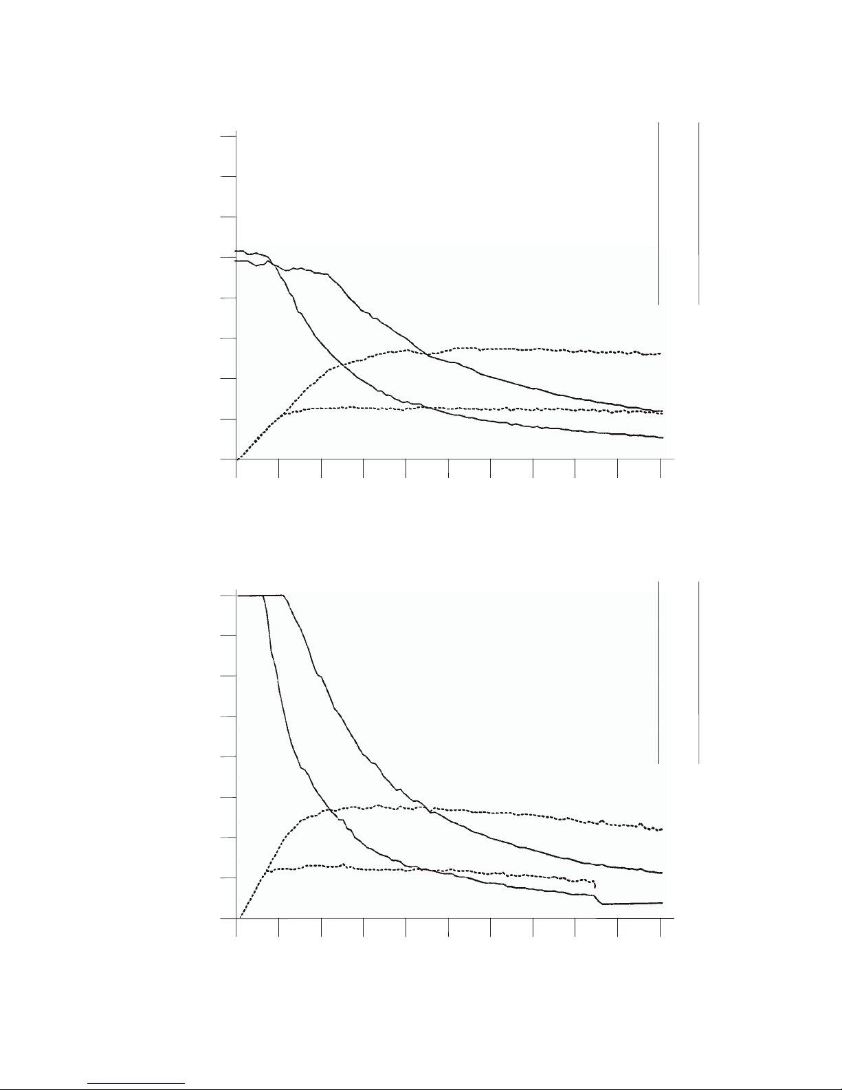
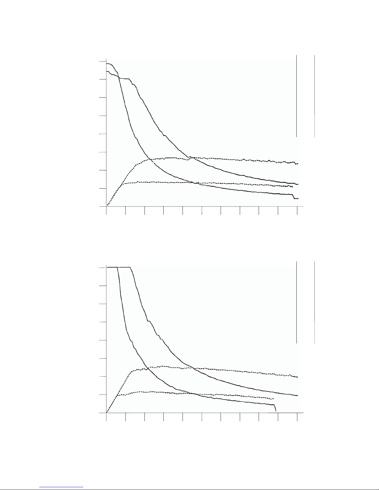
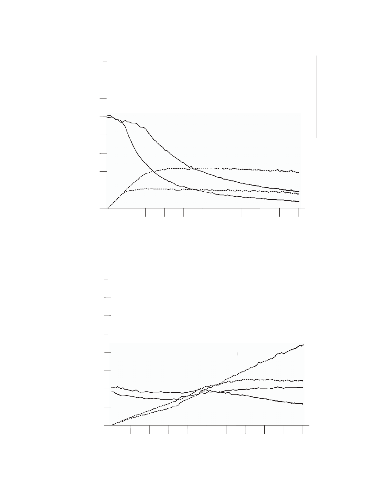
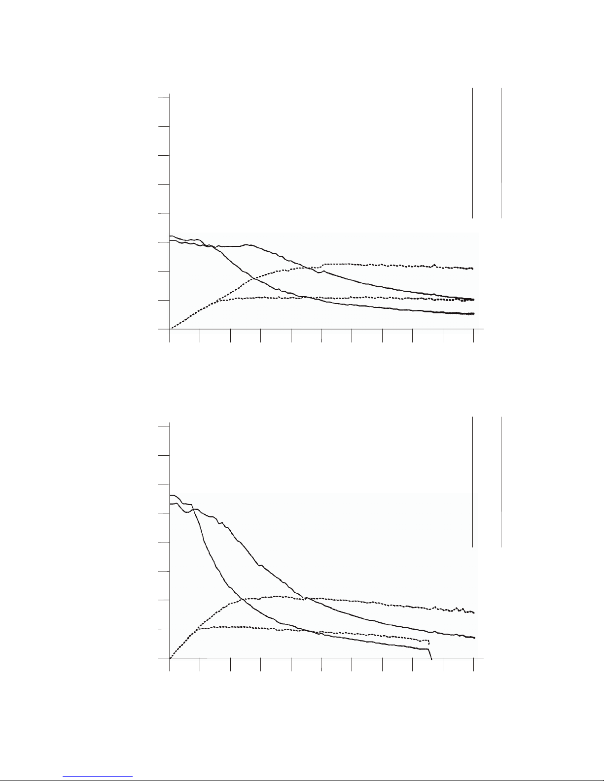
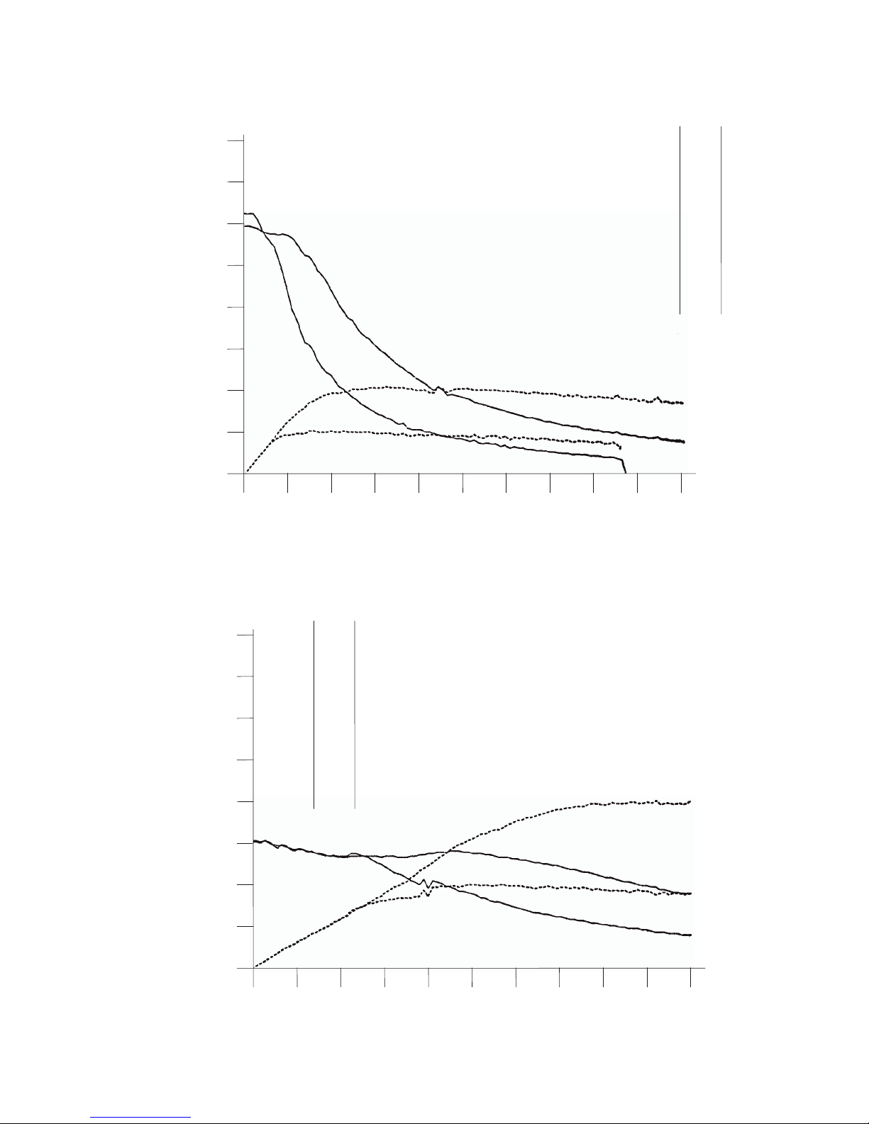
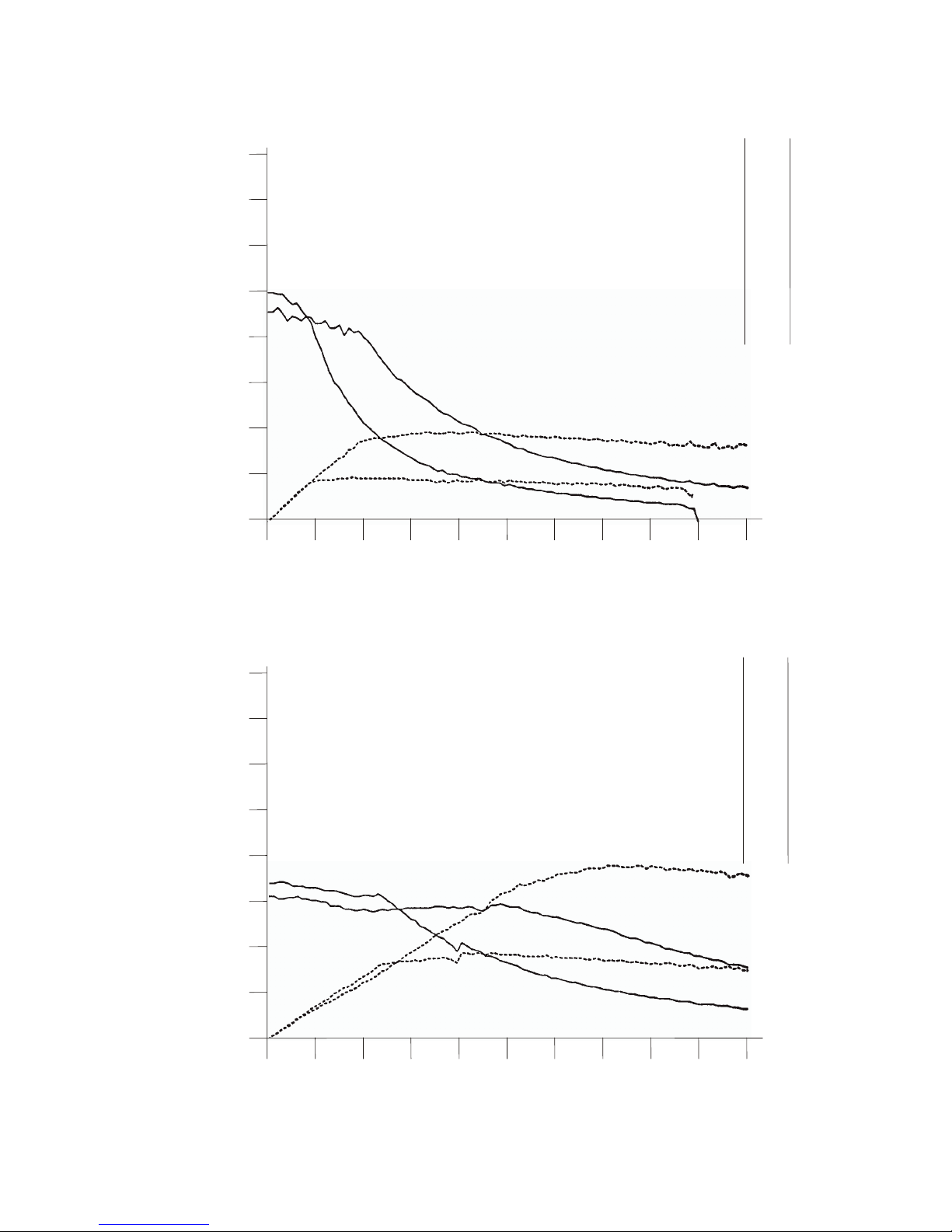
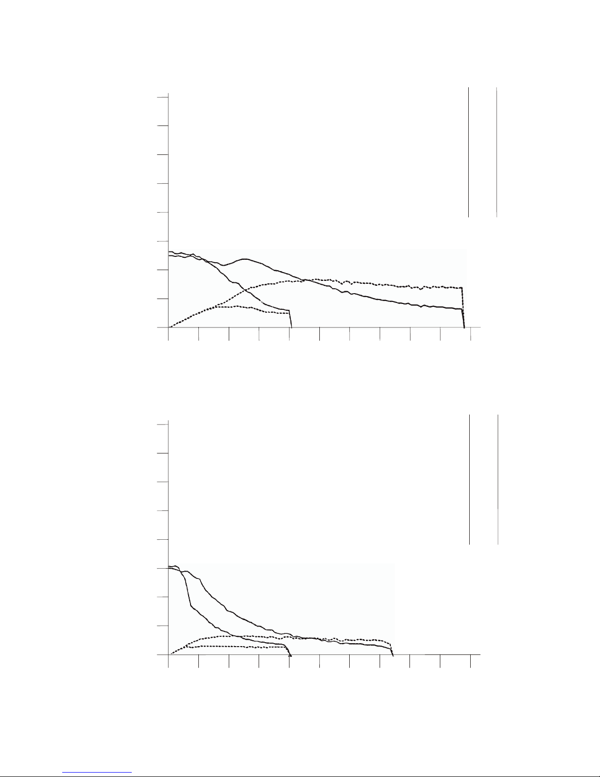
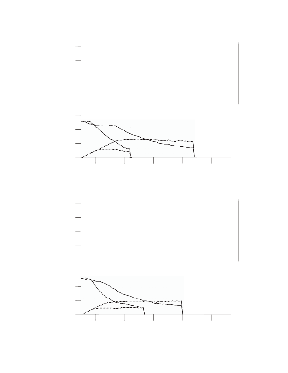
The following speed-torque and speed-power curves were plotted using a Centent
CN0165 and various manufacturers' motors. Two sets of curves are plotted per motor.
One set was taken with a 54 VDC power supply voltage, the other with a 27 VDC power
supply voltage. The dynamometer’s moment of inertia was adjusted to be equivalent to
the motor’s moment of inertia. The test data was collected at 100 points between zero
and 10,000 full steps per second. The CN0165 was set to 10 microstep resolution and the
motors configured for high performance (parallel) operation.
The data set for 27 volts DC power supply is also representative of a series configured
motor run at 54 volts DC power supply. The solid line graph is the motor torque,
measured in ounce/inches. The dotted line graph is the mechanical power output of the
motor, measured in watts.
Page 30
CENTENT CN0165 MICROSTEP DRIVE
26
Figure 15 - SUPERIOR M093-FD14
Figure 16 - RAPIDSYN 34D-9214R
50
1K
0K
1K
2K
3K
4K
5K
6K
7K
8K
9K
10K
397
397
380
279
215
171
140
117
99
85
74
0
88
168
185
190
190
186
181
176
171
165
2K 3K
FULL STEPS PER
SUPERIOR M093-FD14
TORQUE
(OZ/IN)
POWER
(WATTS)
4K 5K 6K 7K 8K 9K 10K
100
150
200
250
300
350
400
50
1K
0K
1K
2K
3K
4K
5K
6K
7K
8K
9K
10K
224
213
204
195
163
137
118
99
87
76
67
0
47
90
129
145
152
157
154
154
152
148
2K 3K
FULL STEPS PER
RAPIDSYN 34D-9214R
TORQUE
(OZ/IN)
POWER
(WATTS)
4K 5K 6K 7K 8K 9K 10K
100
150
200
250
300
350
400
Page 31
SPEED-TORQUE CURVES
27
Figure 17 - WARNER SM-200-0125-BC
Figure 18 - MAE MY200-2240-460A8
25
1K
0K
1K
2K
3K
4K
5K
6K
7K
8K
9K
10K
81
73
71
67
60
65
69
66
67
67
68
0
16
31
45
53
72
92
106
126
133
152
2K 3K
FULL STEPS PER
WARNER SM-200-0125-BC
TORQUE
(OZ/IN)
POWER
(WATTS)
4K 5K 6K 7K 8K 9K 10K
50
75
100
125
150
175
200
25
1K
0K
1K
2K
3K
4K
5K
6K
7K
8K
9K
10K
145
144
138
139
124
113
99
86
74
67
59
0
31
61
92
109
125
132
134
132
133
131
2K 3K
FULL STEPS PER
MAE MY200-2240-460A8
TORQUE
(OZ/IN)
POWER
(WATTS)
4K 5K 6K 7K 8K 9K 10K
50
75
100
125
150
175
200
Page 32
CENTENT CN0165 MICROSTEP DRIVE
28
Figure 19 - MAE MY200-3437-400A8
Figure 20 - SUPERIOR M093-FD11
50
1K
0K
1K
2K
3K
4K
5K
6K
7K
8K
9K
10K
224
238
229
184
151
120
101
85
73
65
57
0
52
101
122
134
133
134
133
129
130
127
2K 3K
FULL STEPS PER
MAE MY200-3437-400A8
TORQUE
(OZ/IN)
POWER
(WATTS)
4K 5K 6K 7K 8K 9K 10K
100
150
200
250
300
350
400
50
1K
0K
1K
2K
3K
4K
5K
6K
7K
8K
9K
10K
397
397
294
199
149
117
93
78
63
53
45
0
88
130
132
132
129
124
120
113
105
100
2K 3K
FULL STEPS PER
SUPERIOR M093-FD11
TORQUE
(OZ/IN)
POWER
(WATTS)
4K 5K 6K 7K 8K 9K 10K
100
150
200
250
300
350
400
Page 33
SPEED-TORQUE CURVES
29
Figure 21 - BODINE 34T3 2005
Figure 22 - JAPAN SERVO KP88M2-001
50
1K
0K
1K
2K
3K
4K
5K
6K
7K
8K
9K
10K
368
346
277
188
141
113
93
76
65
56
48
0
76
123
125
125
126
124
118
116
111
107
2K 3K
FULL STEPS PER
BODINE 34T3 2005
TORQUE
(OZ/IN)
POWER
(WATTS)
4K 5K 6K 7K 8K 9K 10K
100
150
200
250
300
350
400
50
1K
0K
1K
2K
3K
4K
5K
6K
7K
8K
9K
10K
397
397
269
188
135
107
87
73
60
51
43
0
88
119
125
120
119
116
113
107
102
96
2K 3K
FULL STEPS PER
JAPAN SERVO KP88M2-001
TORQUE
(OZ/IN)
POWER
(WATTS)
4K 5K 6K 7K 8K 9K 10K
100
150
200
250
300
350
400
Page 34
CENTENT CN0165 MICROSTEP DRIVE
30
Figure 23 - RAPIDSYN 34D-9206A
Figure 24 - VEXTA PH265-05
50
1K
0K
1K
2K
3K
4K
5K
6K
7K
8K
9K
10K
246
234
213
156
121
98
81
67
57
49
43
0
51
94
103
107
108
107
104
102
99
96
2K 3K
FULL STEPS PER
RAPIDSYN 34D-9206A
TORQUE
(OZ/IN)
POWER
(WATTS)
4K 5K 6K 7K 8K 9K 10K
100
150
200
250
300
350
400
25
1K
0K
1K
2K
3K
4K
5K
6K
7K
8K
9K
10K
46
39
36
35
39
43
46
47
49
48
49
0
8
16
23
35
48
62
73
87
96
108
2K 3K
FULL STEPS PER
VEXTA PH265-05
TORQUE
(OZ/IN)
POWER
(WATTS)
4K 5K 6K 7K 8K 9K 10K
50
75
100
125
150
175
200
Page 35
SPEED-TORQUE CURVES
31
Figure 25 - VEXTA PH296-01
Figure 26 - BODINE 34T2 2104
50
1K
0K
1K
2K
3K
4K
5K
6K
7K
8K
9K
10K
151
141
140
135
113
93
81
68
57
49
43
0
31
62
90
100
103
107
106
102
99
96
2K 3K
FULL STEPS PER
VE
X
TA PH296-01
TORQUE
(
OZ/IN)
POWER
(WATTS)
4K 5K 6K 7K 8K 9K 10K
100
150
200
250
300
350
400
50
1K
0K
1K
2K
3K
4K
5K
6K
7K
8K
9K
10K
262
248
213
159
118
93
74
60
49
42
35
0
54
94
105
105
103
99
94
88
83
79
2K 3K
FULL STEPS PER
BODINE 34T2 2104
TORQUE
(OZ/IN)
POWER
(WATTS)
4K 5K 6K 7K 8K 9K 10K
100
150
200
250
300
350
400
Page 36
CENTENT CN0165 MICROSTEP DRIVE
32
Figure 27 - SUPERIOR M092-FD08
Figure 28 - SUPERIOR ME61FD-80083
50
1K
0K
1K
2K
3K
4K
5K
6K
7K
8K
9K
10K
294
283
219
156
113
92
74
62
51
43
37
0
62
97
103
100
101
99
96
91
87
82
2K 3K
FULL STEPS PER
SUPERIOR M092-FD08
TORQUE
(OZ/IN)
POWER
(WATTS)
4K 5K 6K 7K 8K 9K 10K
100
150
200
250
300
350
400
25
1K
0K
1K
2K
3K
4K
5K
6K
7K
8K
9K
10K
74
70
65
65
67
68
64
60
54
49
44
0
15
29
43
59
76
86
94
96
97
98
2K 3K
FULL STEPS PER
SUPERIOR ME61FD-80083
TORQUE
(OZ/IN)
POWER
(WATTS)
4K 5K 6K 7K 8K 9K 10K
50
75
100
125
150
175
200
Page 37
SPEED-TORQUE CURVES
33
Figure 29 - JAPAN SERVO KPM8AM2-001
Figure 30 - VEXTA PH268-05
50
1K
0K
1K
2K
3K
4K
5K
6K
7K
8K
9K
10K
224
212
198
143
109
85
70
57
48
42
37
0
47
87
95
96
95
93
89
85
83
82
2K 3K
FULL STEPS PER
JAPAN SERVO KPM8AM2-
TORQUE
(OZ/IN)
POWER
(WATTS)
4K 5K 6K 7K 8K 9K 10K
100
150
200
250
300
350
400
25
1K
0K
1K
2K
3K
4K
5K
6K
7K
8K
9K
10K
78
75
70
71
71
73
67
60
53
46
40
0
16
31
47
63
81
89
94
95
93
89
2K 3K
FULL STEPS PER
VEXTA PH268-05
TORQUE
(OZ/IN)
POWER
(WATTS)
4K 5K 6K 7K 8K 9K 10K
50
75
100
125
150
175
200
Page 38
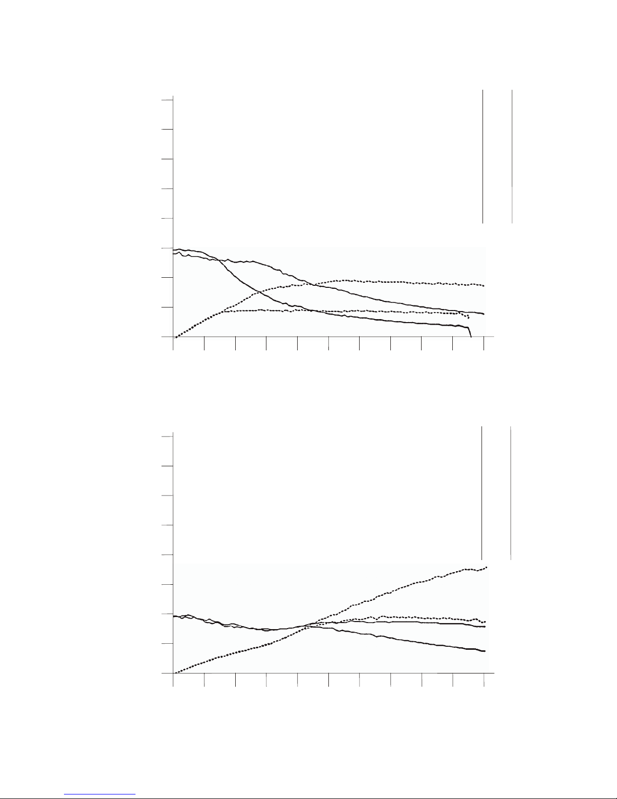
CENTENT CN0165 MICROSTEP DRIVE
34
Figure 31 - SUPERIOR M091-FD09
Figure 32 - SUPERIOR M061-FD08
50
1K
0K
1K
2K
3K
4K
5K
6K
7K
8K
9K
10K
137
129
123
118
98
82
70
59
49
43
37
0
28
54
78
87
91
93
91
88
87
82
2K 3K
FULL STEPS PER
SUPERIOR M091-FD09
TORQUE
(OZ/IN)
POWER
(WATTS)
4K 5K 6K 7K 8K 9K 10K
100
150
200
250
300
350
400
25
1K
0K
1K
2K
3K
4K
5K
6K
7K
8K
9K
10K
48
44
39
36
39
43
44
43
43
42
40
0
9
17
24
35
48
59
67
77
85
89
2K 3K
FULL STEPS PER
SUPERIOR M061-FD08
TORQUE
(OZ/IN)
POWER
(WATTS)
4K 5K 6K 7K 8K 9K 10K
50
75
100
125
150
175
200
Page 39
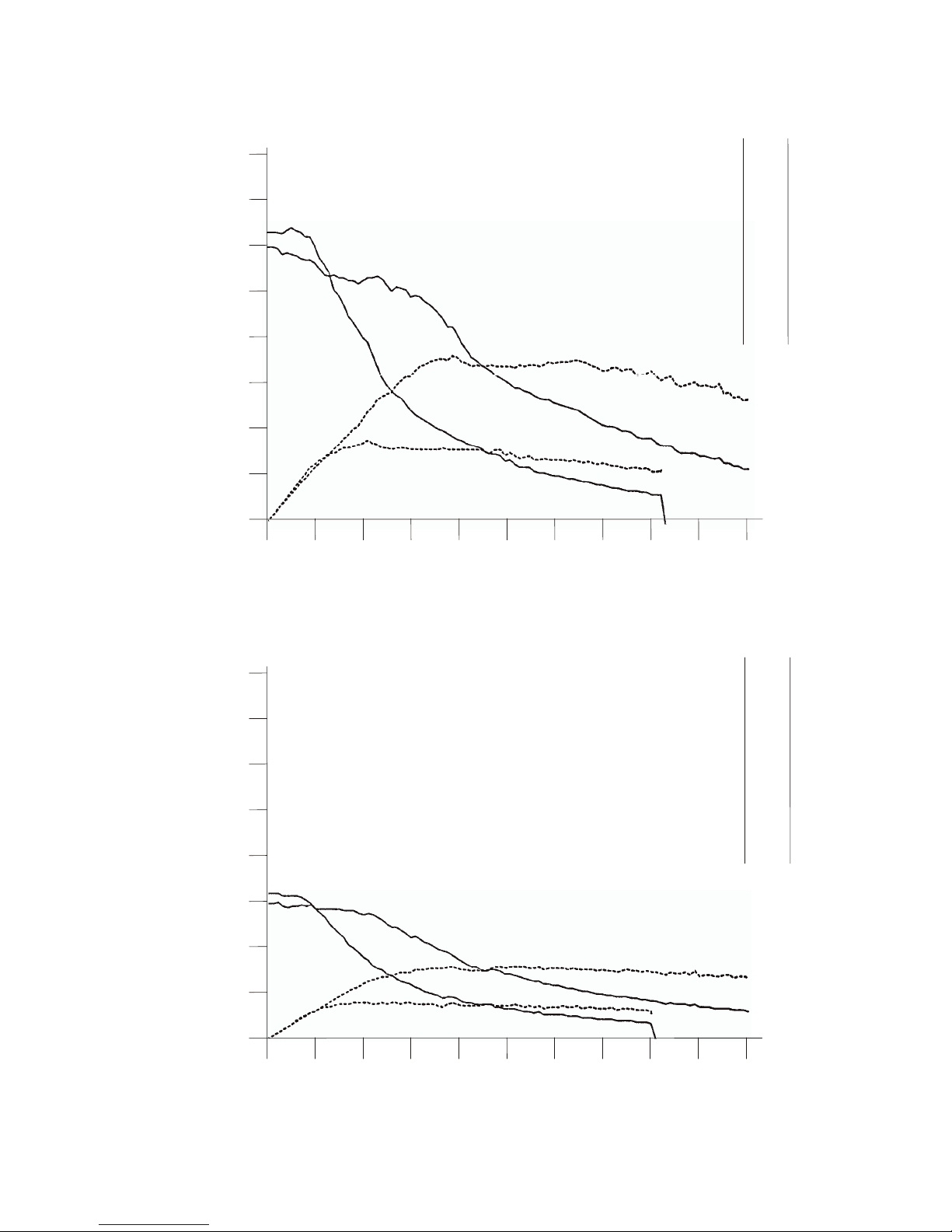
SPEED-TORQUE CURVES
35
Figure 33 - RAPIDSYN 23D-6306
Figure 34 - RAPIDSYN 34-9601A
25
1K
0K
1K
2K
3K
4K
5K
6K
7K
8K
9K
10K
147
138
129
120
101
77
65
53
46
37
30
0
30
57
80
89
85
87
83
82
74
67
2K 3K
FULL STEPS PER
RAPIDSYN 23D-6306
TORQUE
(OZ/IN)
POWER
(WATTS)
4K 5K 6K 7K 8K 9K 10K
50
75
100
125
150
175
200
50
1K
0K
1K
2K
3K
4K
5K
6K
7K
8K
9K
10K
146
140
134
109
87
70
57
48
40
34
29
0
31
59
72
77
77
76
74
71
68
65
2K 3K
FULL STEPS PER
RAPIDSYN 34-9601A
TORQUE
(OZ/IN)
POWER
(WATTS)
4K 5K 6K 7K 8K 9K 10K
100
150
200
250
300
350
400
Page 40
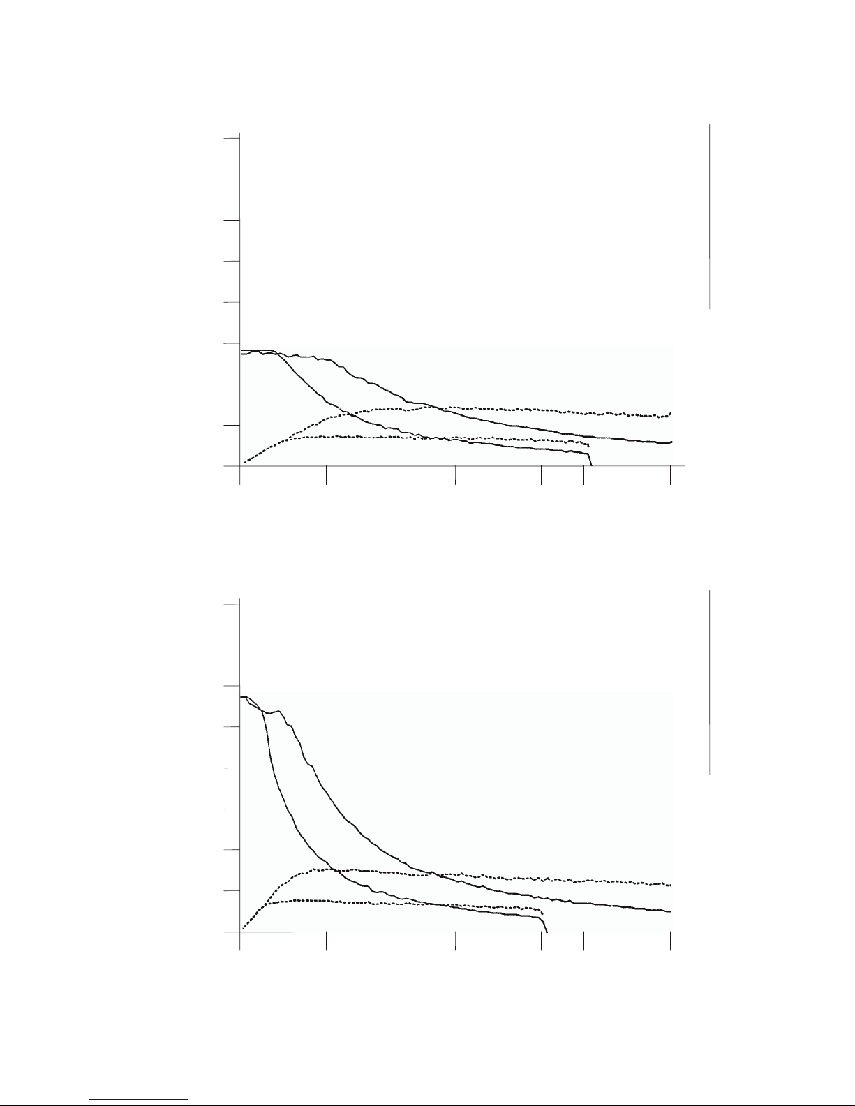
CENTENT CN0165 MICROSTEP DRIVE
36
Figure 35 - SUPERIOR M091-FD-6006
Figure 36 - VEXTA PH299-01
50
1K
0K
1K
2K
3K
4K
5K
6K
7K
8K
9K
10K
135
131
124
98
76
63
51
43
35
31
29
0
29
55
65
67
70
68
67
63
62
65
2K 3K
FULL STEPS PER
SUPERIOR M091-FD-6006
TORQUE
(OZ/IN)
POWER
(WATTS)
4K 5K 6K 7K 8K 9K 10K
100
150
200
250
300
350
400
50
1K
0K
1K
2K
3K
4K
5K
6K
7K
8K
9K
10K
283
260
170
112
78
63
49
43
35
31
26
0
57
75
74
69
70
66
67
63
62
58
2K 3K
FULL STEPS PER
VEXTA PH299-01
TORQUE
(OZ/IN)
POWER
(WATTS)
4K 5K 6K 7K 8K 9K 10K
100
150
200
250
300
350
400
Page 41
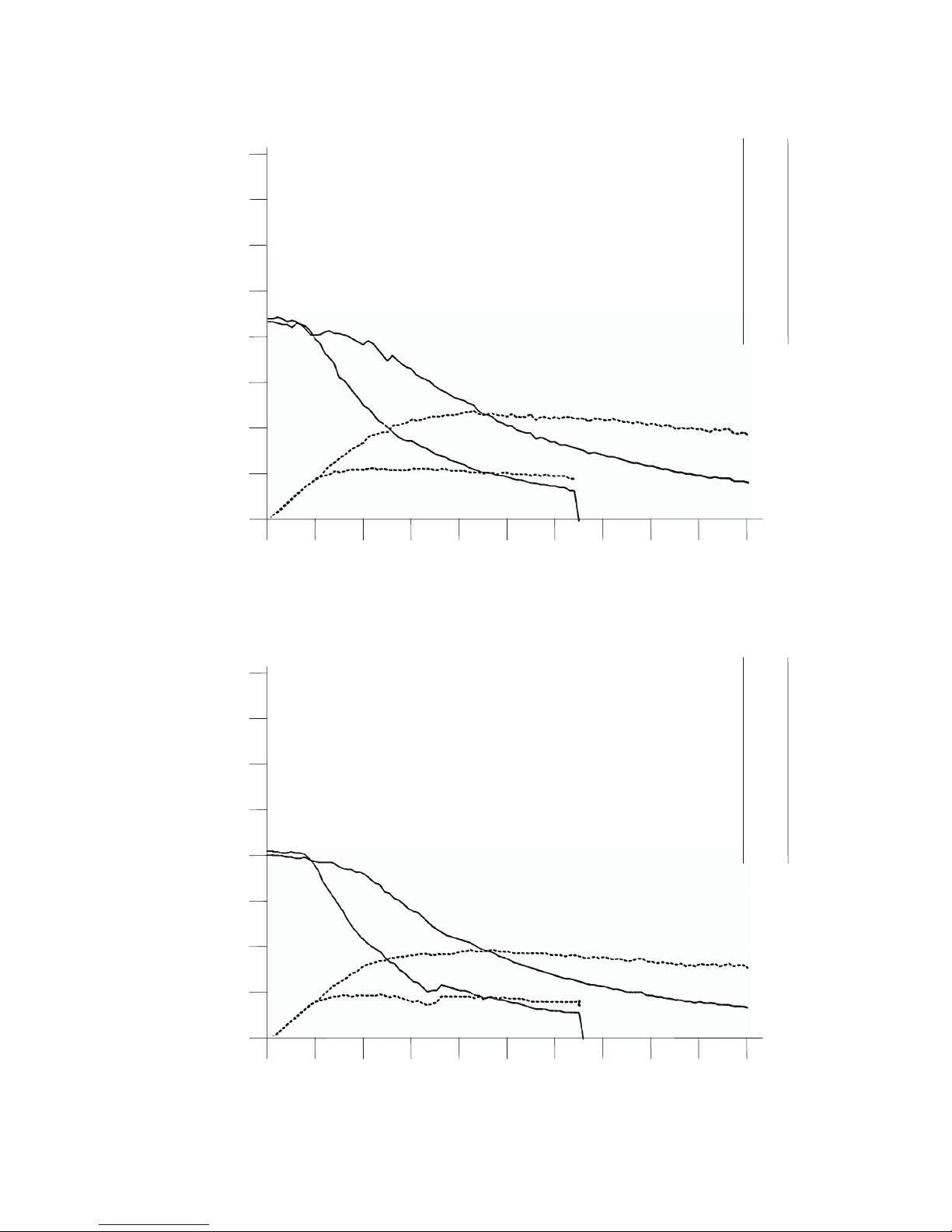
SPEED-TORQUE CURVES
37
Figure 37 - RAPIDSYN 23D-6204
Figure 38 - SUPERIOR M062-FD04
25
1K
0K
1K
2K
3K
4K
5K
6K
7K
8K
9K
10K
106
99
93
81
64
50
42
35
29
24
21
0
21
41
53
57
56
55
54
52
49
46
2K 3K
FULL STEPS PER
RAPIDSYN 23D-6204
TORQUE
(OZ/IN)
POWER
(WATTS)
4K 5K 6K 7K 8K 9K 10K
50
75
100
125
150
175
200
25
1K
0K
1K
2K
3K
4K
5K
6K
7K
8K
9K
10K
99
95
88
67
53
42
34
28
24
21
17
0
21
39
45
46
47
45
44
42
41
39
2K 3K
FULL STEPS PER
SUPERIOR M062-FD04
TORQUE
(OZ/IN)
POWER
(WATTS)
4K 5K 6K 7K 8K 9K 10K
50
75
100
125
150
175
200
Page 42
CENTENT CN0165 MICROSTEP DRIVE
38
Figure 39 - WARNER SM-200-0080-B8
Figure 40 - SUPERIOR M091-FD03
25
1K
0K
1K
2K
3K
4K
5K
6K
7K
8K
9K
10K
59
56
53
53
44
36
28
23
19
17
0
0
12
23
35
39
40
37
36
34
34
0
2K 3K
FULL STEPS PER
TORQUE
(OZ/IN)
POWER
(WATTS)
4K 5K 6K 7K 8K 9K 10K
50
75
100
125
150
175
200
WARNER SM-200-0080-B8
50
1K
0K
1K
2K
3K
4K
5K
6K
7K
8K
9K
10K
149
131
76
51
37
26
21
17
0
0
0
0
29
33
34
33
29
29
26
0
0
0
2K 3K
FULL STEPS PER
SUPERIOR M091-FD03
TORQUE
(OZ/IN)
POWER
(WATTS)
4K 5K 6K 7K 8K 9K 10K
100
150
200
250
300
350
400
Page 43
SPEED-TORQUE CURVES
39
Figure 41 - RAPIDSYN 23D-6102
Figure 42 - SUPERIOR M061-FD02
25
1K
0K
1K
2K
3K
4K
5K
6K
7K
8K
9K
10K
63
56
55
47
36
28
22
18
0
0
0
0
12
24
31
32
31
30
29
0
0
0
2K 3K
FULL STEPS PER
RAPIDSYN 23D-6102
TORQUE
(OZ/IN)
POWER
(WATTS)
4K 5K 6K 7K 8K 9K 10K
50
75
100
125
150
175
200
25
1K
0K
1K
2K
3K
4K
5K
6K
7K
8K
9K
10K
63
59
50
35
28
21
17
0
0
0
0
0
13
22
23
24
23
23
0
0
0
0
2K 3K
FULL STEPS PER
SUPERIOR M061-FD02
TORQUE
(OZ/IN)
POWER
(WATTS)
4K 5K 6K 7K 8K 9K 10K
50
75
100
125
150
175
200
Page 44
CENTENT CN0165 MICROSTEP DRIVE
40
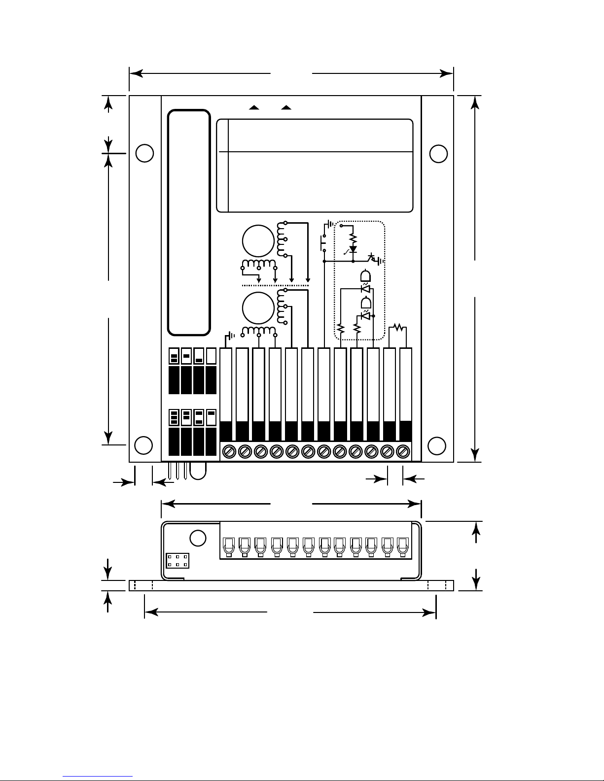
Figure 43 - CN0165 FULL SCALE DRAWING
SUPPLY GROUND
+18 to 80 VOLTS DC
PHASE A
PHASE B
PHASE C
PHASE D
FAULT/RESET
DIRECTION
STEP PULSE
+5 VOLTS DC
CURRENT SET
GROUND
CENTENT CN0165
HIGH RESOLUTION MICROSTEP DRIVE
123456789101112
3.625”
92.1mm
4.0”
101.6mm
4.5”
114.3mm
3.625”
92.1mm
0.85”
21.5mm
0.125”
3.2mm
3.25”
82.6mm
0.186”
4.7mm
0.20”
5.1mm
0.7”
17.8mm
PARALLEL
SERIES
WINDING CONFIGURATIONS
180
180
(INTERNAL)
RESET
FAULT LE D
+12V
SEE CURRENT SET TABLE
PARALLEL SERIES
.25A
.50A
.75A
1.0A
1.5A
2.0A
2.5A
3.0A
3.5A
4.0A
4.5A
5.0A
5.5A
6.0A
6.5A
7.0A
7.5A
8.0A
8.5A
9.0A
9.5A
10.0A
0.5A
1.0A
1.5A
2.0A
3.0A
4.0A
5.0A
6.0A
7.0A
8.0A
9.0A
10.0A
11.0A
12.0A
13.0A
14.0A
15.0A
16.0A
17.0A
18.0A
19.0A
20.0A
1.2K
2.4K
3.9K
5.1K
8.2K
12K
16K
20K
24K
30K
39K
47K
56K
68K
91K
110K
150K
180K
270K
430K
910K
OPEN
RESISTOR
T
R
I
M
S
T
A
NDBYCUR
REN
T
Page 45

CENTENT CN0165 MICROSTEP DRIVE
41
CN0165 SPECIFICATION
MIN MAX UNITS
ELECTRICAL
Resolution 1 256 µStep
Supply voltage 18 80 VDC
Current (no motor) 50 60 mA
Motor phase current 0.1 10 A
Motor phase inductance 0.5 -- mH
Step Pulse Input
Logic '1' voltage 1.8 5.0 VDC
Logic '0' current 3 20 mA
Pulse width 'high' 500 -- nSec
Pulse width 'low' 500 -- nSec
Rise time -- -- --
Fall time -- -- - Frequency -- 1.0 MHz
Direction Input
Logic '1' voltage 1.8 5.0 VDC
Logic '0' current 3 20 mA
MIN MAX UNITS
ENVIRONMENTAL
Operating temperature -20 +75 °C
-4 +167 °F
Humidity 0 100 %
Shock -- 100 G
MIN MAX UNITS
MECHANICAL
Weight 17 19 oz.
482 539 gram
Mounting screw size 6 8 #
Terminal Screw Torque 4.5 lb/in
Size (L x W x H)
4.75
× 4.00 × 0.85
in.
121
× 102 × 21.5
mm
Mounting hole centers
3.625
× 3.625
in.
92
× 92
mm
Table 7 - Specification
Page 46

CENTENT CN0165 MICROSTEP DRIVE
42
A
acceleration............16, 17, 18, 24
accuracy.................12, 17, 23, 25
amplifier...................................12
amplitude .....................17, 18, 23
angular resolution ....................16
anode........................................ 10
anti-resonance................1, 17, 18
automatic current standby..........1
B
Bodine 34T2 2104 ...................31
Bodine 34T3 2005 ...................29
brackets......................................3
bridge.........................................1
C
center-tap ...................................7
chassis........................................3
chopper ......................................1
current
profile...................2, 14, 16, 25
set resistor.4, 11, 18, 20, 22, 24
set table.............................2, 13
standby .............................1, 15
current profile ..........2, 14, 16, 25
current set resistor4, 11, 18, 20, 22,
24
current set table....................2, 13
current standby.....................1, 15
D
damage...........2, 4, 12, 14, 16, 19
damping .....................................1
deceleration..............4, 16, 18, 24
diode ..................................2, 4, 9
direction...................................10
Direction Input...............1, 10, 41
distortion............................15, 24
dynamometer ...........................25
E
electrical angle...................16, 24
electrical tape..............................7
epoxy..........................................1
erratic operation..........................6
error angle ................................24
external resistors .......................10
F
fan...............................................3
fault
led .......................1, 2, 9, 14, 16
output..............................1, 3, 9
status.......................................2
terminal.................................16
terminal.........................2, 9, 16
fault led.....................................14
fault LED....................................9
Fault LED.........................1, 2, 16
filter capacitor.............................5
friction......................................19
full step
location .................................14
full step location.................14, 17
function generator ....................15
fuse.............................................4
H
heat sink..................1, 2, 3, 12, 23
heat sink compound....................3
heat sink kit ................................3
heating................1, 19, 20, 22, 23
high frequency............................6
HSK............................................3
I
ideal motor................................24
immunity (noise) ........................1
inactivity (motor)..................2, 15
inductance...........1, 15, 18, 20, 41
instability (midband) ......1, 17, 18
insulation....................................3
internal counters...................9, 16
iron losses...................................1
Page 47

INDEX
43
J
Japan Servo KP88M2-001....... 29
Japan Servo KPM8AM2-001 ..33
jumper...................................... 14
L
light emitting diode................2, 9
linearity........................14, 24, 25
load ..........................5, 22, 23, 24
M
MAE MY200-2240-460A8 .....27
MAE MY200-3437-400A8 .....28
mechanical angle................16, 24
microstep resolution..1, 2, 14, 16,
23, 24, 25
microstepping ..........................17
MOSFET....................................1
motor
leads......................................7
nameplate .......................20, 22
performance....................18, 20
phase outputs....................... 6
smoothness...........................23
speed.....................................23
mounting plate........................... 2
N
noise...................................1, 4, 6
O
offset trimpot .......................2, 15
operational amplifiers.............. 12
option header .............1, 2, 14, 25
opto-isolator......................... 1, 10
overheating ............................1, 9
P
parallel .......................................4
parallel operation. 6, 7, 19, 20, 23
power1, 2, 4, 5, 7, 9, 10, 15, 16, 18,
19, 20, 22, 23, 25
power dissipation.....................23
power supply1, 2, 4, 5, 7, 9, 10, 15,
16, 18, 20, 22, 23, 25
power supply failure...................1
R
Rapidsyn 23D-6102..................39
Rapidsyn 23D-6204..................37
Rapidsyn 23D-6306..................35
Rapidsyn 34-9601A..................35
Rapidsyn 34D-9206A...............30
Rapidsyn 34D-9214R...............26
reset ......................................9, 16
resolution table...........................2
RFI..............................................6
S
series...........................................4
series operation.....6, 7, 19, 20, 23
shorting bars.........................2, 14
speed-power curves..................25
speed-torque curves..................25
standby trimpot.....................2, 15
step pulse......................10, 15, 16
Step Pulse Input........1, 10, 15, 41
Superior M061-FD02...............39
Superior M061-FD08...............34
Superior M062-FD04...............37
Superior M091-FD03...............38
Superior M091-FD09...............34
Superior M091-FD-6006..........36
Superior M092-FD08...............32
Superior M093-FD11...............28
Superior M093-FD14...............26
Superior ME61FD-80083.........32
T
temperature...................2, 3, 9, 41
terminal connector......................2
torque.1, 2, 16, 17, 18, 19, 20, 21,
22, 24, 25
boost circuit ............................1
reaction ...........................16, 17
transistors .......................1, 10, 16
TTL.................................1, 10, 14
U
under-voltage..................1, 16, 17
Page 48

CENTENT CN0165 MICROSTEP DRIVE
44
V
Vexta PH265-05 ......................30
Vexta PH268-05 ......................33
Vexta PH296-01 ......................31
Vexta PH299-01 ......................36
vibration.................12, 15, 16, 17
viscous .......................................1
W
Warner SM-200-0080-B8 ........38
Warner SM-200-0125-BC........27
winding configuration ........19, 23
wire gauge..................................3
Z
zener diode .................................4
 Loading...