

Page 1
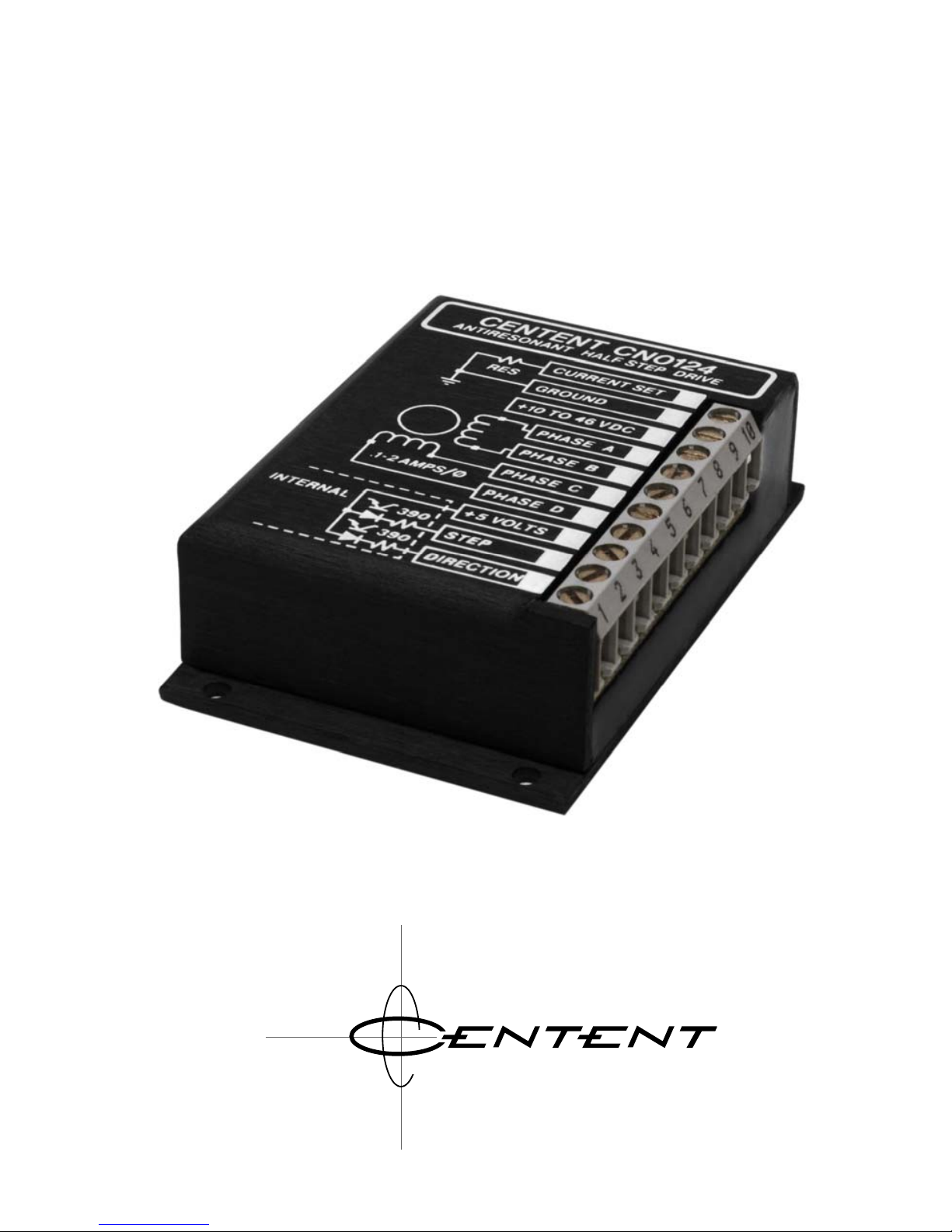
CN0124
STEP MOTOR DRIVE
OPERATING MANUAL
3879 SOUTH MAIN STREET 714-979-6491
SANTAANA, CALIFORNIA 92707-5710 U.S.A.
0 M P A N Y
Page 2

This manual contains information for installing and operating the
following Centent Company product:
CN0124 Half-Step Drive
Centent and the Centent Company logo are trademarks of Centent
Company. Other trademarks, tradenames, and service marks
owned or registered by any other company and used in this
manual are the property of their respective companies.
Copyright
© 2019 Centent Company
3879 South Main Street
Santa Ana, CA 97207
All Rights Reserved
Page 3

GENERAL DESCRIPTION
The Centent CN0124 is a small high frequency chopper type half-step drive
for use with 4, 6, and 8 wire PM hybrid step motors rated from .1 to 2
amps per phase. It incorporates a dual 'H' bridge output and features
anti-resonance circuitry that eliminates mid-band instability. The CN0124
has opto-isolated step and direction inputs that can either be driven
directly by TTL gates or by open collector transistor outputs. The power
supply voltage can range from 10 VDC to 46 VDC and may be unregulated.
The control measures only 2" x 3" x .8", and weighs approximately 5.5
ounces. It is encapsulated in a heat conductive epoxy that makes it
suitable for use in harsh environments.
Centent Company also manufactures full/half-step drives and high
resolution microstep drives designed to run step motors rated up to 20
amps per phase.
INSTALLATION
The CN0124 generates 10 watts of heat per amp of motor current. The
drive must be adequately heat sunk at current set values greater than .5
amps. Maximum case temperature must not exceed 70°C (158°F).
No terminals or connectors are required on the wiring to the CN0124 drive.
A wire size of 16-22 gauge is recommended. Either stranded or solid
conductor wire may be used. The insulation should be stripped back .25
inches and the wire left untinned.
TERMINAL 1 DIRECTION
The DIRECTION input is sampled on every step pulse to determine which
direction the motor will move. A low level on the DIRECTION terminal will
result in clockwise motion while a high level will cause counter-clockwise
motion. The input is TTL compatible and requires a current sink of 8 mA to
operate.
TERMINAL 2 STEP
Half-stepping of the motor occurs on the '1 to 0' logic transition of the
STEP input. The maximum step rate is 50 KHz when driven with a square
wave. The minimum allowable pulse 'on' or 'off' time is 10 microseconds.
The input is TTL compatible and requires a current sink of 8 mA to
operate.
1
Page 4
TERMINAL 3 +5 VOLTS
This input provides the power supply for the STEP and DIRECTION
opto-couplers. It must be supplied from the user's 5 volt logic power
supply. It provides power only to the anodes of the opto-coupler LEDs;
electrically isolating the STEP and DIRECTION inputs from the other
circuitry in the drive.
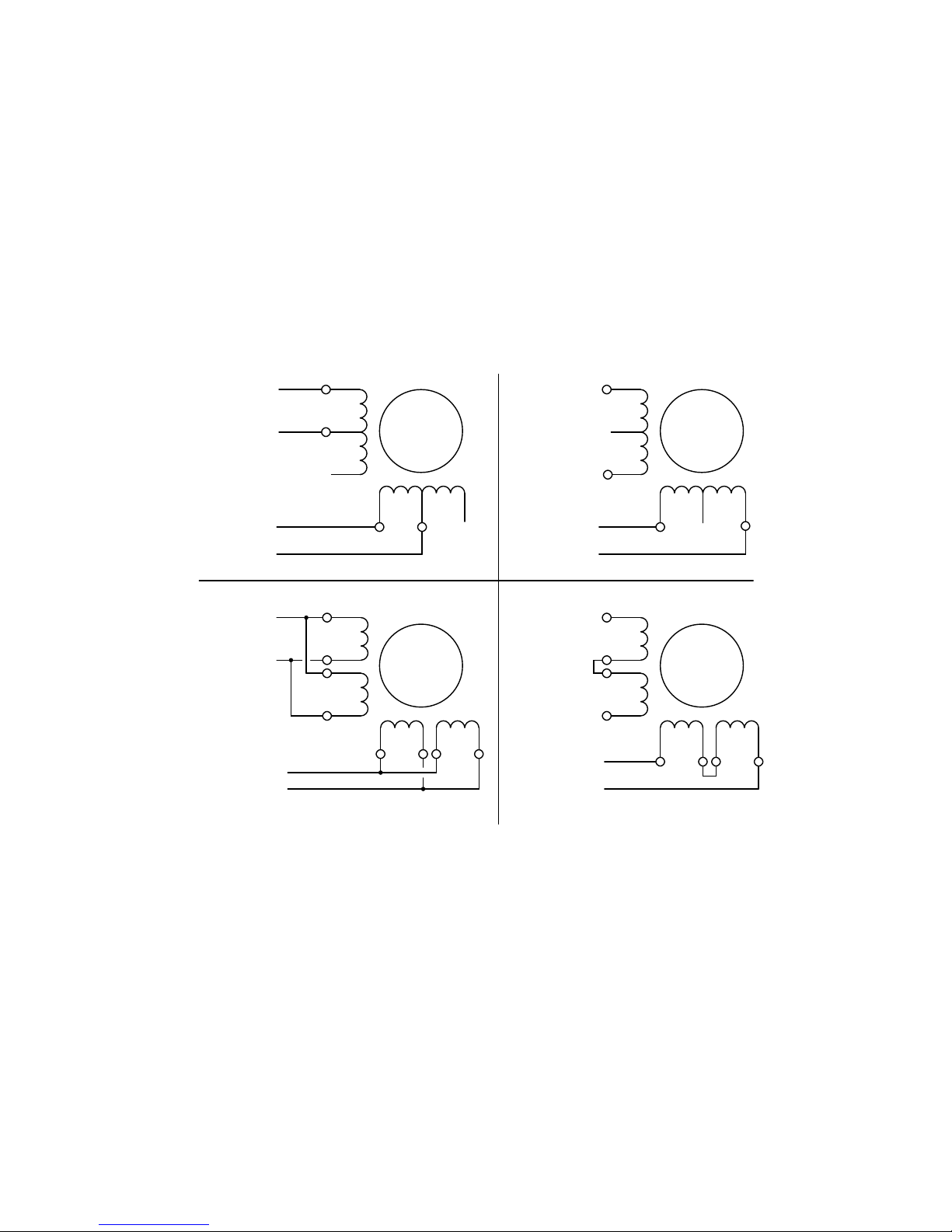
TERMINAL 4, 5, 6, 7 PHASE A, B & C, D
The motor output terminals are organized as pairs (PHASE A, B and
PHASE C, D) and drive the motor's phase windings. One motor winding
goes to PHASE A & PHASE B, the other goes to PHASE C & PHASE D.
n.c .
n.c .
PHASE A
PHASE C
PAR AL LE L SE R IE S
PHASE B
PHASE D
PHASE A
PHASE C
PHASE B
PHASE D
n.c .
n.c .
PHASE A
PHASE C
PHASE B
PHASE D
PHASE A
PHASE C
PHASE B
PHASE D
6
6
88
With 6 or 8 wire motors the user has the option of connecting the motor in
high performance (parallel) or low performance (series) configuration.
Parallel operation has twice the maximum motor power output, at the
expense of greater motor and drive heating. The diagrams show both
configurations for 6 and 8 wire motors. Unused wires should not be left
exposed; insulate them to prevent damage to the control or motor.
TERMINAL 8 +10 TO 46 VDC
This is the power supply input to the CN0124. The minimum voltage is
10 VDC; the maximum is 46 VDC. The power supply may be unregulated,
however the ripple voltage must be limited to a maximum of 10% of the DC
output voltage.
2
Page 5
TERMINAL 9 GROUND
This is the CN0124's power supply GROUND input. It also serves as the
return side of the current set resistor (Terminal 10).
TERMINAL 10 CURRENT SET
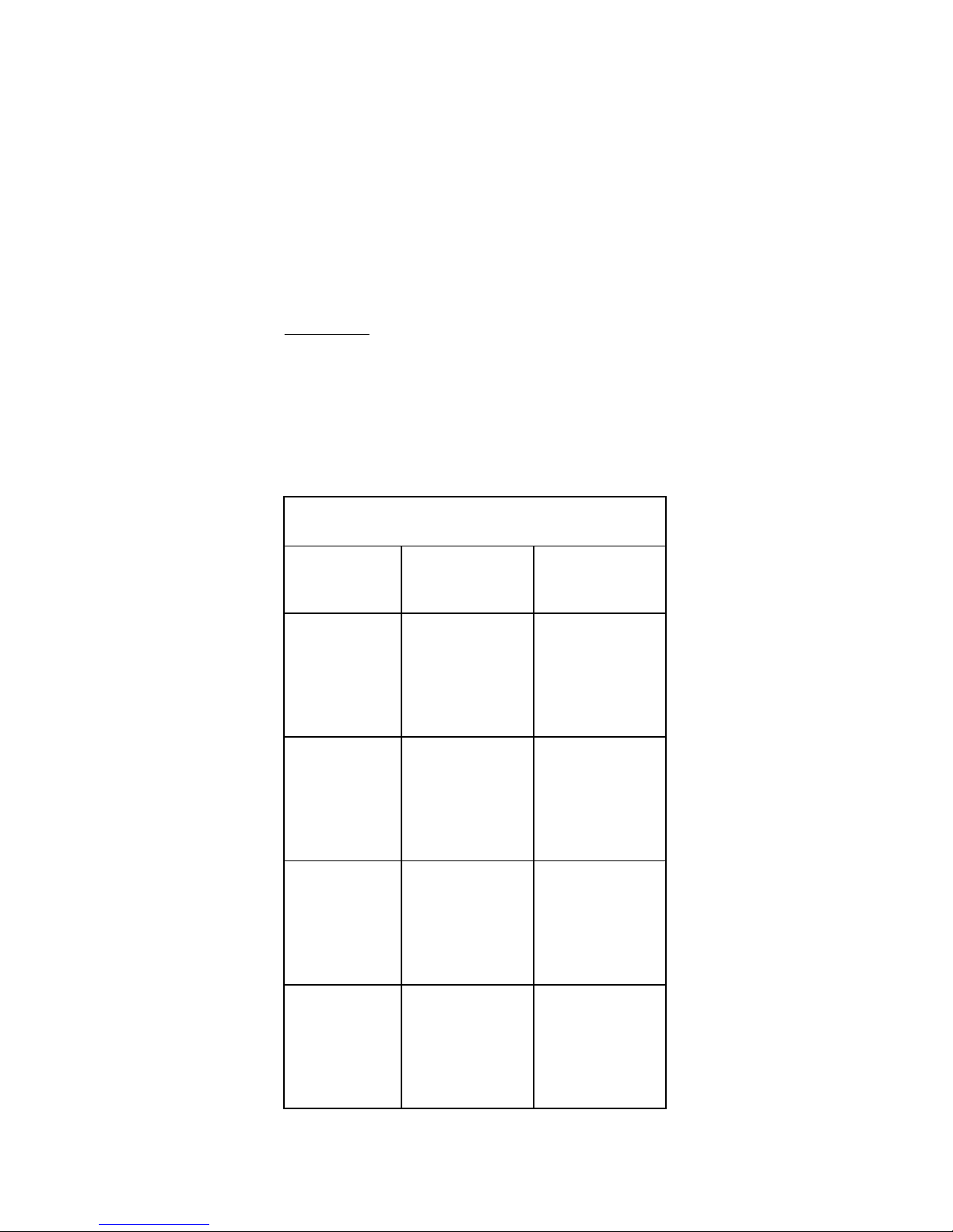
A resistor from the CURRENT SET pin to the GROUND pin sets the
operating phase current. The resistor value for a motor in the high
performance configuration is calculated from the following formula:
R =
780
I
(2-
I
)
SET
SET
Where R is the current set resistor
value in ohms and I
SET
is the desired
phase current in amperes (parallel)
The CURRENT SET TABLE lists resistor values for both parallel and series
operation. Use the high performance column in the table when selecting
phase current for 4 wire motors.
CURRENT SET TABLE
AMPERES
(SERIES)
AMPERES
(PARALLEL)
RESTISTOR
(OHMS)
.2
.4
.6
.8
1.0
.1
.2
.3
.4
.5
39
82
130
200
270
1.2
1.4
1.6
1.8
2.0
.6
.7
.8
.9
1.0
330
430
510
620
750
2.2
2.4
2.6
2.8
3.0
1.1
1.2
1.3
1.4
1.5
1.0 K
1.2 K
1.5 K
1.6 K
2.4 K
3.2
3.4
3.6
3.8
4.0
1.6
1.7
1.8
1.9
2.0
3.0 K
4.2 K
6.8 K
15 K
OPEN
3
Page 6
13 981076
5
42
3.0”
76.2mm
1.5”
38.1mm
0.125”
3.2mm
0.094”
2.4mm
0.2”
5.1mm
2.626”
66.7mm
2.8”
71.1mm
0.85”
21.6mm
2.0”
50.8mm
CURRENT SET
GROUND
+10 TO 46 VDC
PHASE A
PHASE B
PHASE C
PHASE D
+5 VOLTS
STEP
DIRECTION
CENTENT CN0124
ANTIRESO NANT HAL F S T EP DRIVE
390
390
INTERNAL
.1-2 AMPS /
ø
RES
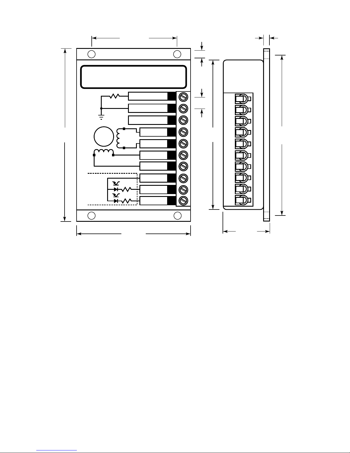
SPECIFICATIONS
MIN. MAX. UNITS
ELECTRICAL
Resolution
1
/2
1
/2 Step
Supply voltage 10 46 VDC
Motor phase current .1 2 A
STEP PULSE INPUT
Step rate -- 50 KHz
Logic '0' current 8 10 mA
Pulse width 10 --
μSec
ENVIRONMENTAL / MECHANICAL
Operating temperature -20 +70
°C
Weight 5 6 oz.
Mounting screw size 2 4 #
Terminal Screw Torque
4.5 lb/in
Size (L x W x H) 3 x 2 x .8 inches
Mounting hole centers 2.8 x 1.5 inches
4
 Loading...