

Page 1
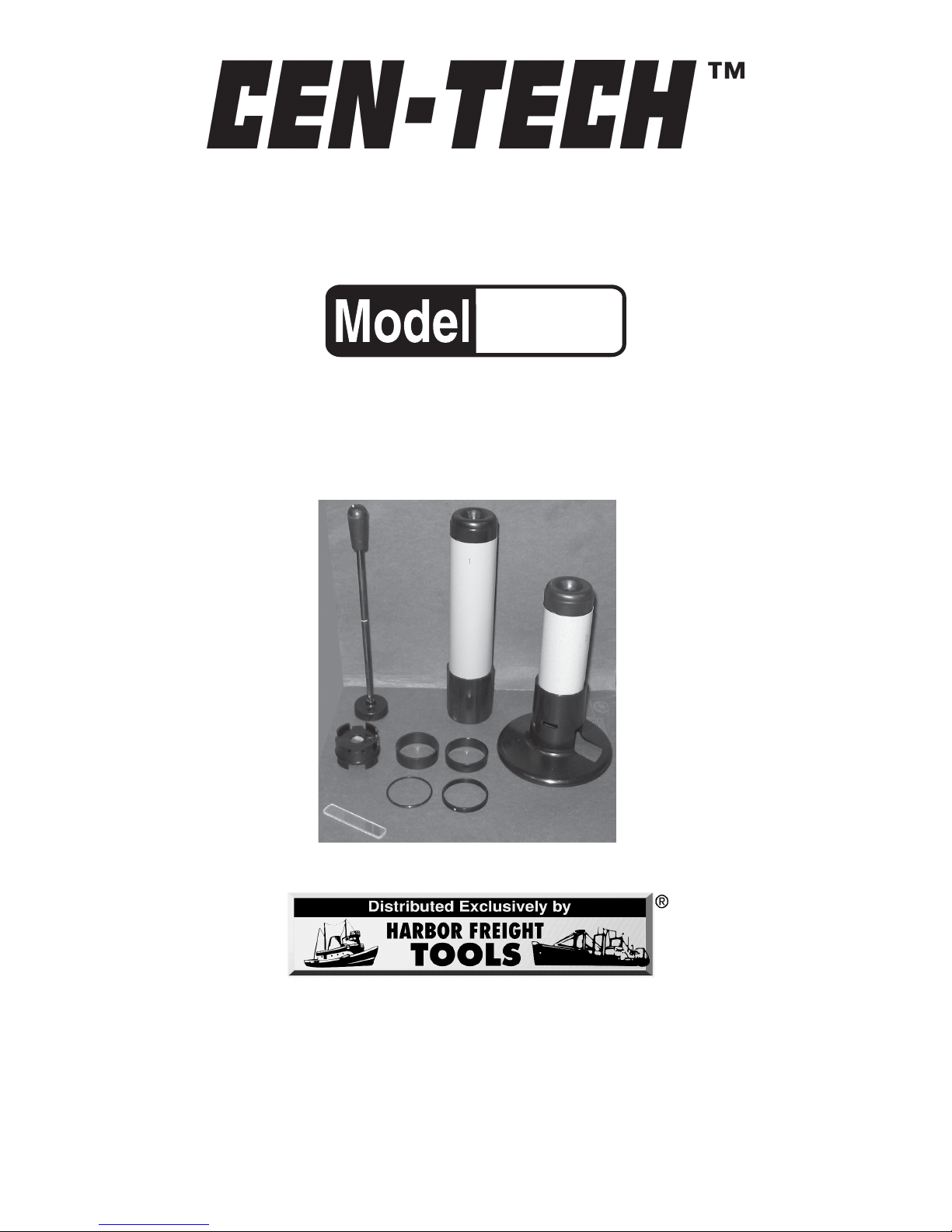
Junior Microscope KitJunior Microscope Kit
Junior Microscope KitJunior Microscope Kit
Junior Microscope Kit
ASSEMBLY AND OPERATING INSTRUCTIONS
3491 Mission Oaks Blvd., Camarillo, CA 93011
Visit our Web site at http://www.harborfreight.com
Copyright © 2005 by Harbor Freight Tools®. All rights reser ved. No por tion of this
manual or any artwork contained herein may be reproduced in any shape or form
without the express written consent of Harbor F reight Tools.
For technical questions and replacement parts, please call 1-800-444-3353
93233
Due to continuing improvements, actual product may differ slightly from the
product described herein.
Page 2
SKU 93233
For technical questions please call 1-800-444-3353
Page 2
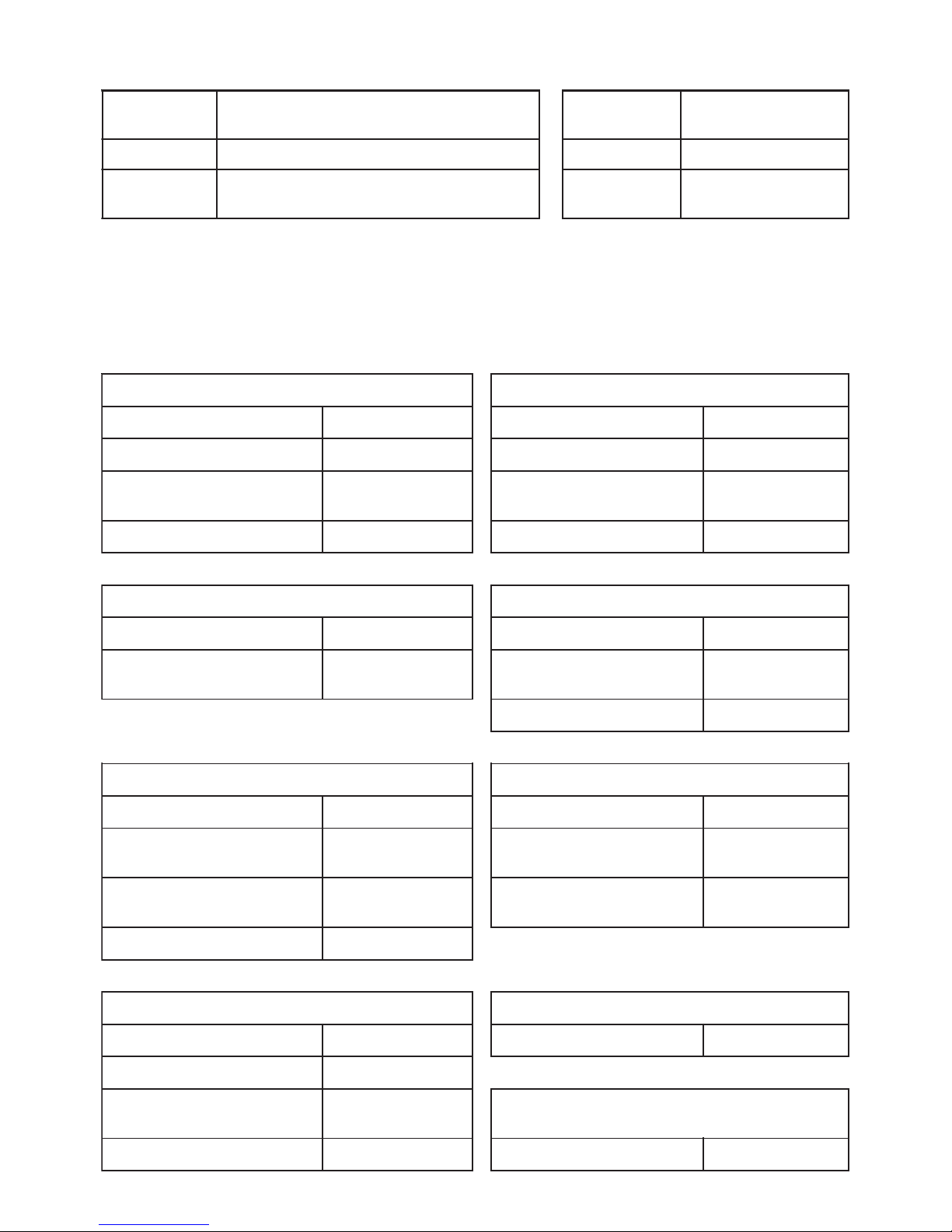
Specifications
* Close supervision by a responsible adult is required.
Applications
This instrument may be assembled in 9 different configurations, including Magnifiers,
T elescopes and Microscopes . Each configuration off ers different optic specifications.
:noitcurtsnoC
leetS,gnibuTmunimulA,scitsalpomrehT
sesneLssalGdnadoR
:noitacilppA
epocseleT,reifingaM
epocs
orciMdna
:ylbmessAsmroflarevesnidelbmessadnaH:rofelbatiuS*41-7deganerdlihC
GNINRAW
rehtoronuSehttayltceridk
ooltonoD
tnemurtsnisihthtiwsecruosthgilgnorts
:thgieWteN.SBL04.1
epocseleTnaelilaG1# epocseleTdnaHlairtserreT5#
:noitacifingaMX4:noitacifingaMX02
:weiVfoelgnA°4.3:weiVfoelgnA°
2
:snoisnemiDllarevO
mm34:retemaiDxaM
mm532:htgneL
:snoisnemiDllarevO
mm34:retemaiDxaM
mm543:htgneL
:thgieW.g
K541.0:thgieW.gK541.0
reifingaMcipocseleT2# epocsorciM6#
:noitacifingaMX2:noitacifingaMX71
:snoisnemiDllarevO
m
m34:retemaiDxaM
mm532:htgneL
:snoisnemiDllarevO
mm011:retemaiDxaM
mm091:htgneL
:thgieW.gK581.0
epocseleTrelp
eKlaimonortsA3# epocsorciM7#
:noitacifingaMX21:noitacifingaMX53
:weiVfoelgnA°4:snoisnemiDllarevO
mm011:retemai
DxaM
mm091:htgneL
:snoisnemiDllarevO
mm34:retemaiDxaM
mm532:htgneL
:thgieW.gK581.0
:thgieW.gK051.0
epocseleTdn
aHlairtserreT4# reifingaM8#
:noitacifingaMX01:noitacifingaMX71
:weiVfoelgnA°4
:snoisnemiDllarevO
mm34:retemaiD
xaM
mm543:htgneL
reifingaM9#
:thgieW.gK522.0:noitacifingaMX5
Page 3

SKU 93233
For technical questions please call 1-800-444-3353
Page 3
Save This Manual
You will need the manual for the saf ety warnings and precautions, assembly
instructions, operating and maintenance procedures, parts list and diagram. Keep
your invoice with this manual. Write the invoice number on the inside of the front
cover . K eep the manual and invoice in a saf e and dry place for future reference .
Safety Warnings and Precautions
W ARNING: When using this device, basic safety precautions should alwa ys be
followed to reduce the risk of personal injury and damage to equipment.
Read all instructions before using this instrument!
1. W ARNING! Do not look at the Sun or other strong light sour ces through
this instrument. Injury to eyes, even blindness may result. Do not use
this instrument to look at a Solar eclipse.
2. Observe work area conditions. Do not use tools or instruments in damp or
wet locations. Don’t expose to rain.
3. Store idle equipment. When not in use, tools and instruments must be
stored in a dry location to inhibit rust. They should be put away properly to
prevent loss of small parts or damage.
4. Maintain instruments with care. Keep tools and instruments maintained
and clean for better and safer performance. The various parts must be kept
clean, dry , and free from oil and g rease at all times. When cleaning lenses
use only clean lens paper and an approved lens cleaner .
5. Stay alert. Watch what you are doing and use common sense. Do not walk
or run with the instrument held to your eye. Do not look at bright lights through
the instrument.
6. Check for damaged parts. Before using any tool or instrument, any part
that appears damaged should be carefully checked to determine that it will
operate properly and perform its intended function. Check for alignment and
binding of moving parts; any broken parts or mounting fixtures; and any other
condition that may affect proper operation. Any part that is damaged should
be properly repaired or replaced by a qualified technician.
7. Replacement parts and accessories. When servicing, use only identical
replacement parts. Use of any other parts will void the warranty. Approved
accessories are available from Harbor F reight T ools.
Page 4
SKU 93233
For technical questions please call 1-800-444-3353
Page 4
Warning: The warnings, cautions, and instructions discussed in this instruction
manual cannot cover all possible conditions and situations that ma y occur. It
must be understood by the operator that common sense and caution are factors
which cannot be built into this product, b ut must be supplied by the operator .
Unpacking
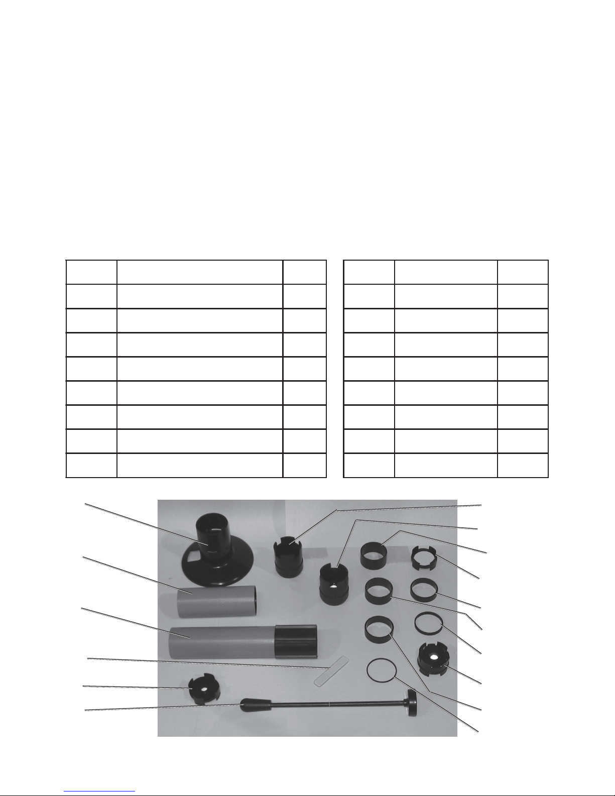
When unpacking, check to make sure that all accessories listed below are
included, and that the product is intact and undamaged.
If any parts are missing or broken, please call Harbor Freight Tools at the number
on the cover of this manual.
#traPnoitpircseD.YTQ#traPnoitpircseD.YTQ
10ydoB190recapSmm8.11
20ebutwarD101,recapSmm51
30esaBepocsorciM111recapSmm8.91
40sneL
gnitcelloC121recapSmm311
50sneLnoisrevnI231recapSmm2.611
60eceipeyEsneLnoisreviD141recapSmm121
70eceipeyEsneLcirtemmyS151e
dilSssalG1
80sneLevitcejbO161doRylbmessA1
03
02
01
15
05
16
07
06
14
08
11
13
10
04
12
09
Page 5
SKU 93233
For technical questions please call 1-800-444-3353
Page 5
About Telescopes and Microscopes
For thousands of years mankind has sought ways of looking farther to see
distant objects, or looking closer to better see small objects.
Phoenicians cooking on sand discovered glass around 3500 BCE, but it
took about 5,000 years more for glass to be shaped into a lens for the first telescope. A spectacle maker named Hans Lippershey (c1570-c1619) of Holland
looked at a church steeple through two lenses placed one in front of the other and
saw that the image was magnified. Lippershey is often credited with the invention of
the telescope, but he almost certainly was not the first to make one.
The telescope was introduced to astronomy in 1609 by the great Italian
scientist Galileo Galilei, who became the first man to see the craters of the moon,
and who went on to discover sunspots , the four large moons of J upiter , and the
rings of Saturn. Galileo’ s telescope had limited magnification and a narrow field of
view . Galileo could see no more than a quarter of the moon’s f ace without
repositioning his telescope.
Later, better telescopes using mirrors and v arious combinations of lenses
have been developed.
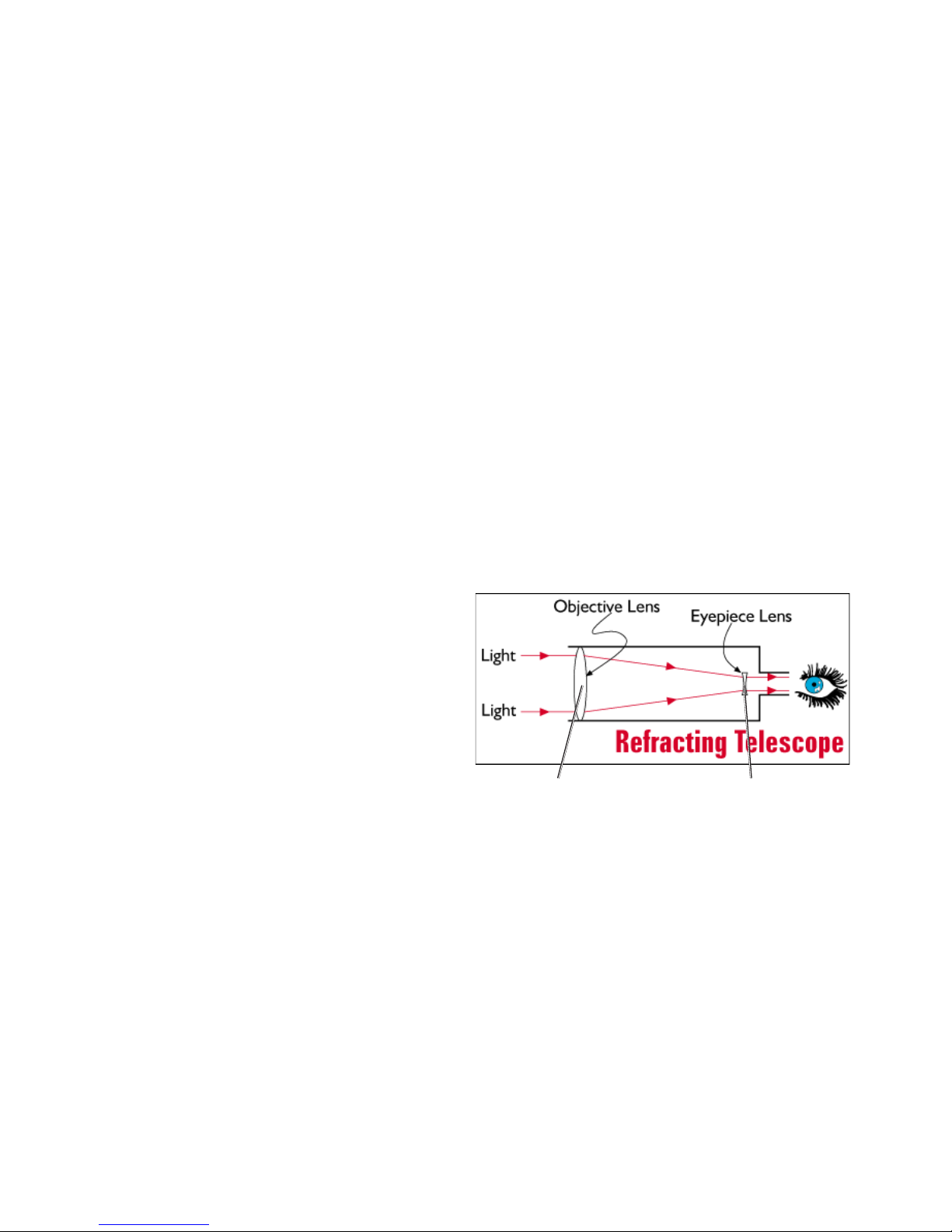
Refracting telescopes use
lenses to gather and bend light making
things seem larger . The lenses used in
refracting telescopes are called
concave and convex. Convex (curved
outward) lenses bend light inward,
making things bigger , but blurry .
Concave (curved inward) lenses bend
light outward, making things appear
small. A combination of these two
lenses can be used to adjust the
apparent size of objects, and make
them appear in focus.
This set contains lenses of different combinations of concave and convex
lenses. Some are individual lenses, and some are combinations of lenses
cemented together.
As you build and experiment with the various combinations of lenses,
think about how each one magnifies or reduces, bends or redirects light.
All lenses have an “Angle of View” which is a measure of the angle the
light is bent by the lens. This is also known as a “Focal Length” which is the
distance from the lens that the light bent by the lens comes back together in
focus. The Body, Drawtube, Ey epieces and Spacers included in this kit allo w y ou
to adjust for the Focal Length of any combination of lenses.
convex lens concave lens
Page 6

SKU 93233
For technical questions please call 1-800-444-3353
Page 6
Understanding the various parts in your kit
Before assembling any optical device, please read the instructions. The various
components work together in different ways to produce a specific instrument. After
you understand how each of these parts works, you may experiment to find new
wa ys to put them together .
Objective Lens #8 is a magnifying lens. It is made of two lenses cemented
together . A lens which is conv e x on both sides has a lens which is flat on one side
and concave on the other attached to it. The smaller flat/concave lens helps
sharpen the image seen through the double convex lens. When using Objective
Lens #8, the flat side is always pointed toward the object being observed. The
rounded, convex side is pointed toward the eyepiece.
Collecting Lens #4 is a combination of three lenses cemented together . A flat/
concave lens is nearest the objective. It is mounted onto a convex/flat lens which
has a flat/flat lens mounted on the inside nearest the eyepiece. Th is lens helps align
the image in the image plane, that means the image appears flat in front of the eye.
Inversion Lenses #5 are used to turn the image right side up. A curious effect of
convex lenses like #8 is that, in addition to enlarging the image, they flip them top
to bottom. Inversion lenses are used in “terrestrial” telescopes, which are used on
land. Without an inversion lens it might be confusing to see a bird on a branch
upside down. Inversion lenses are often not used in “astronomical” telescopes,
since stars and planets usually look about the same whether they are upside down
or not. Inversions in astronomical telescopes are confusing only when looking at
familiar objects like the moon. For that reason, some astronomical telescopes
include inversion lenses.
Eyepiece #6 is called a “diversion” lens because it bends light outward. It is a
concave lens that is used in combination with a convex magnifying lens like # 8.
Convex lenses bend light inward, and concave lenses bend light outward. When
used together at the proper focal length, they produce a magnified image with the
light in alignment again. This is the simple design that Gallileo used, and is the
basic refracting telescope illustrated on page 5.
Eyepiece #7 is a “symmetric” combination of lenses. This consists of two sets of
opposite design lenses mounted in opposition to each other. The effect of this lens
is to magnify the image without distortion.
The Body, Drawtube, Ey epieces and Spacers are all pro vided to adjust the f ocal
length of any instrument you assemble from this kit. It is necessary to adjust the
focal length to result in an image in the eyepiece which is in focus.
A note on magnification. Magnification is produced by the interaction of lenses of
various sizes and shapes positioned in a certain relation to each other. It is the
perception of an image being larger than it appears in nature. Magnification is
described as being so many times (“X”) its appearance with the unaided eye.
Page 7
SKU 93233
For technical questions please call 1-800-444-3353
Page 7
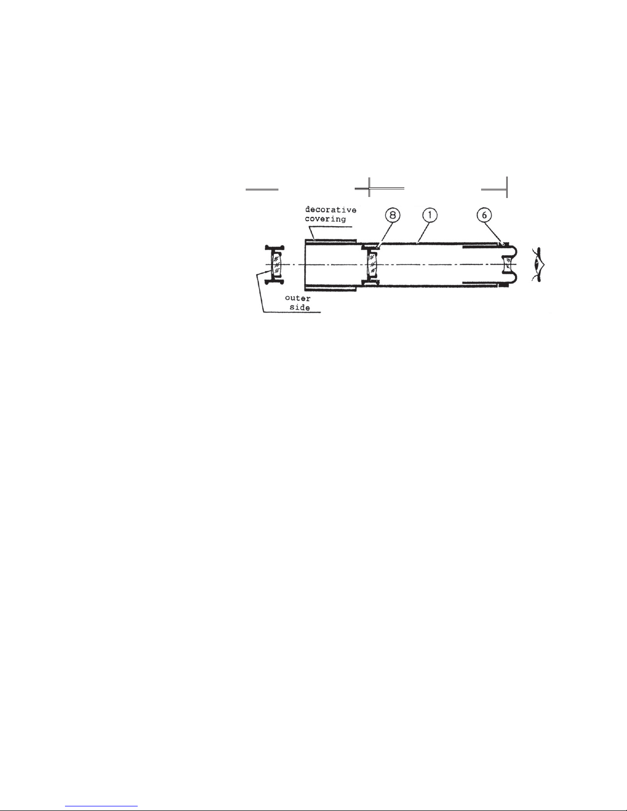
#1 Galilean Hand Telescope
The brilliant 17th century scientist Galileo Gallei designed this telescope
and first recorded using it in 1609. In addition to his many experiments with gravity
and various machines, Galileo wanted to determine if the Earth revolv ed around
the Sun, or the Sun revolv ed around the Earth. The answer to this question w as not
known in his day. His predecessor , Copernicus, had made mathematical
observations to show that the solar system is “heliocentric”, with the Sun at the
center. But he could not
prove it. Others claimed
that the solar system is
“terracentric” with the
Earth at the center. While
not accepted at the time,
Galileo was the first
Western scientist to prove
through observation with a
telescope like this one
that the solar system is
heliocentric.
This sort of telescope has the advantage of allowing in a lot of light, so it
can be used in dark conditions. Its disadvantage is that its field of view and
magnification are very small.
To assemble a Galilean Hand Telescope:
1. Place the Body (01) on a clean, flat work surface.
2. Fit the Objective Lens (08) into the opening near the decorative covering of the
Body (01). Be sure the flat part of the Objective Lens is facing out.
3. Press the Objective Lens (08) into the Body (01) using the Rod (16) until the
mark on the Rod aligns with the outer edge of the Body .
4. Remove the Rod and set it aside. Insert the Diversion Lens Eyepiece (06) into
the other end of the Body (01).
5. To focus this telescope, mov e the Ey epiece (06) slowly in and out.
6. If it is not possible to focus the telescope on a remote object, the Objective
Lens (08) may be in the wrong position, or may not be straight in the Body
(01). Disassemble the telescope, and reassemble correctly following the
above directions.
Galilean Hand T elescope
distance “d”
distance “D”
Page 8
SKU 93233
For technical questions please call 1-800-444-3353
Page 8
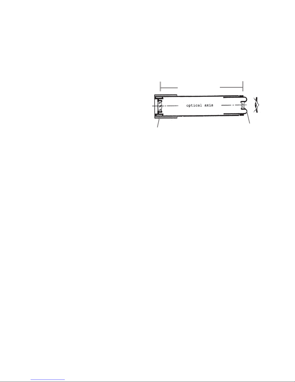
#2 A Telescopic Magnifier
If you set the position of the Objective Lens (08) using the mark on the Rod
(16) as discussed in step 3 on page 7, the telescope is set for a focal length
that will focus on astronomical objects. However , if y ou position the Objective
Lens (08) farther from the Diversion Lens Eyepiece (06), you will set the
telescope for a f ocal length that is much shorter.
To make a Telescopic
Magnifier
1. Insert the Objective Lens (08) into
the very end of the Body (01) at
the end with the decorative
covering.
2. Insert the Diversion Lens
Eyepiece (06) in the other end.
The Telescopic Magnifier is best suited f or looking at objects that are only 1/2
to 2 meters distant (approximately 1/2 to 6 feet).
The distances of the Objective Lens to the Eyepiece and the Objective Lens to
the observed object are “inversely proportional”. That means as one gets
larger , the other gets smaller in some mathematical relationship to each other.
When the Objective Lens was midway in the Body to make the Galilean
Telescope, we could call the small distance from the Objective Lens to the
Eyepiece distance “d”. We were able to focus on a distant object, like the
Moon. We can call that long distance to the Moon “D”.
With the Telescopic Magnifier , we increased the small distance “d” to the end
of the Body, so let’s call the new small distance “d+”. Now the distance to the
observed object is much smaller. Let’s call it distance “D-”.
So we learn that “d” and “D” are inverse to each other. As “d” became “d+”, “D”
became “D-”. Through observation, we can learn that they are also
proportional, that means the differences have a mathematical relationship.
This mathematical relationship shown by telescopes of various lengths and
objects of various distances opened the door for thinking about all sorts of
mathematical relationships in nature; and helped generations of inspired
thinkers create the foundations of modern science.
T elescopic Magnifier
distance “d+”
(08)
(06)
Page 9
SKU 93233
For technical questions please call 1-800-444-3353
Page 9
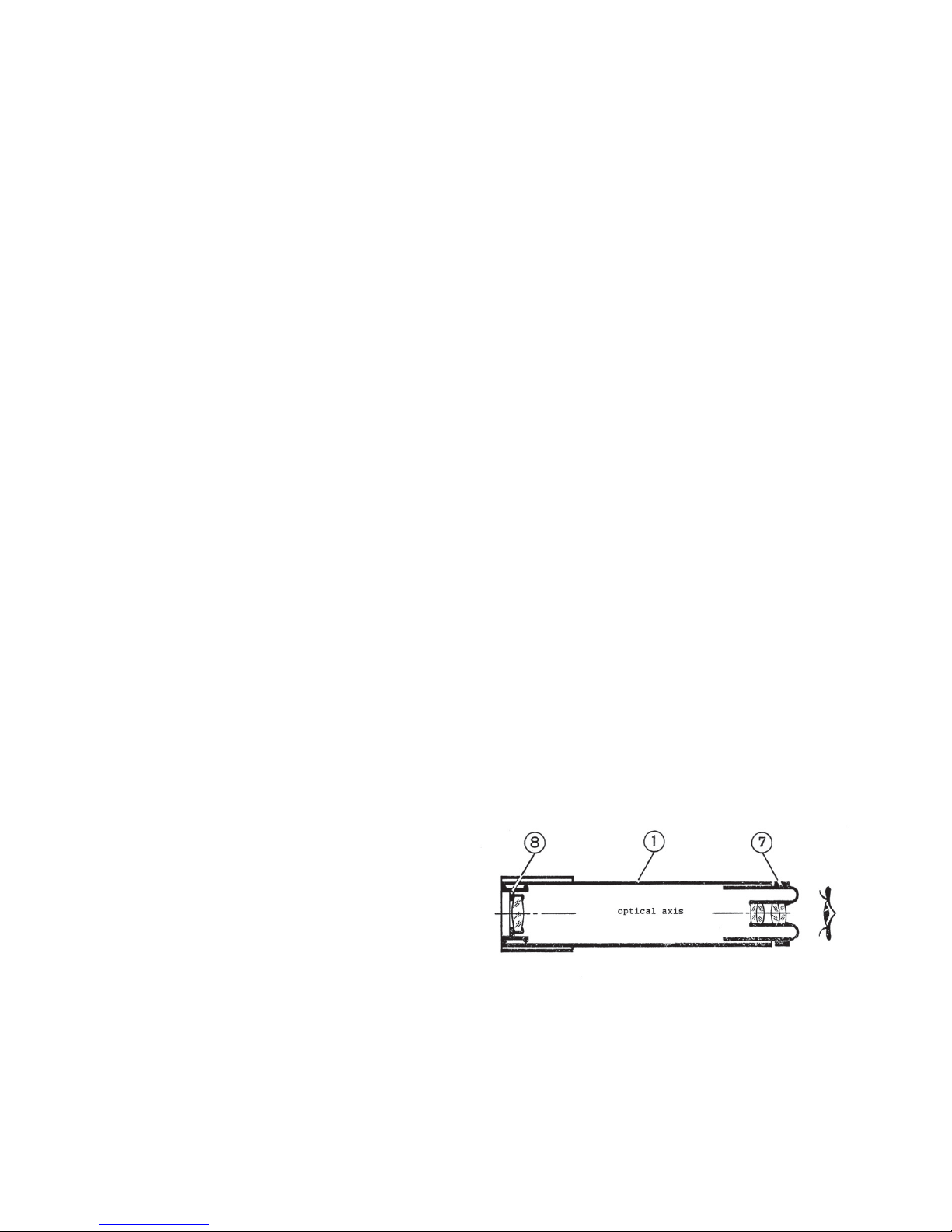
#3 Astronomical Kepler Telescope
Johannes Kepler (1570-1630) w as a German scientist who lived during and
after Galileo’s lifetime. Kepler was very interested in Galileo’s work, and continued
to improve the telescope. He is credited with developing the Symmetric Lens, which
he described in his book “Dioptrics” which w as published in 1611.
When you look at the cross section of the Symmetrical Lens Eyepiece
(07) in the diagram, notice that the space between the two opposite lenses is itself
shaped like a lens. Kepler is credited with recognizing that these “negative spaces”
can be as important in lens optics as lenses themselves.
In 1600 Kepler w as invited to become assistant to T yco Br ache,
mathematician at the court of Emperor Rudolph II of Prague. Brache’ s most
important contribution to modern science was not theory, but his e xtensiv e
observations of the movements of the planets , which K epler assisted him in
collecting.
The famous fictional 19th century sleuth Sherlock Holmes stated “ it is
useless to theorize ahead of the facts”. Brache refused to advance theory of
planetary motion until he had made numerous observations himself, using Kepler’s
improved telescopes. Every clear night for many years Brache carefully observed
and plotted the relative locations of the known planets and prominent stars. By the
time of his death, he had compiled the most accurate and extensive record of
planetary motion ever made. But he had not proposed any additional theories to
explain the facts he had observed.
At Brache’ s death, his e xtensive records were inherited b y Kepler. K epler then
postulated his 3 laws of planetary motion. Later Isaac Newton built upon Kepler’s
laws to form the basis of modern “Newtonian” physics.
T o assemble a Kepler’ s Hand Telescope
1. Insert the Objective Lens (08) into
the end of the Body (01) which has
the decorative covering as you did
to make the Telescopic Magnifier.
2. Insert the Symmetric Lens
Eyepiece (07) in the other end of
the Body.
3. Adjust the position of the
Eyepiece (07) to focus the
instrument.
NOTE: The complex lenses in Kepler’ s symmetrical ey epiece change the simple
“inverse proportion” calculations of focal length. Howev er, if y ou do the math, the
rules still apply. Also, the image seen in a Kepler’s telescope will be inverted.
Kepler’s telescope
Page 10
SKU 93233
For technical questions please call 1-800-444-3353
Page 10
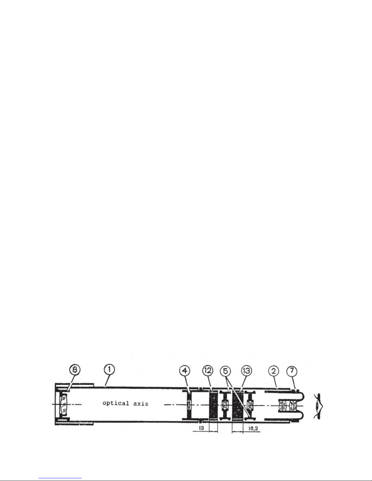
#4 A Terrestrial 10X Hand Telescope
Kepler’s telescope greatly improved on Galileo’s in terms of its magnification
and field of view . Howe ver , Kepler’ s telescope, like Galileo’ s produced an
inverted (upside down) image.
The inversion is caused by the convex sides of the magnifying lens directing
the light wav es past each other , top to bottom and side to side .
Inversion Lenses (05) used in pairs can be used to make the image appear
through the telescope as it does in nature.
The T errestrial 10X Hand T elescope is useful f or seeing things on earth, at a
distance greater than 10 meters (32-1/2 feet).
To assemble the Terrestrial 10X Telescope
1. Fit the Objective Lens (08) into the Body (01) at the end with the decorative
covering.
2. Fit the short end of Collecting Lens (04) into the end of the Drawtube (02).
3. From the other end of the Drawtube, insert 13mm Spacer (12) until it touches
the end of the Collecting Lens.
4. Next insert Inversion Lens (05) with the marking to ward Spacer (12).
5. Next insert 16.2mm Spacer (13)
6. Now insert the other Inversion Lens (05) with the marking “5” to the outside
facing away from 13mm Spacer (12).
7. Insert the Symmetric Eyepiece (07).
8. Insert the Collecting Lens (04) into the Body (01) to join the two parts of the
telescope together .
You can now focus the telescope on objects more than 10 meters a w a y by
adjusting the Eyepiece.
the T errestrial 10X T elescope
Page 11
SKU 93233
For technical questions please call 1-800-444-3353
Page 11
#5 The T errestrial 20X Telescope
This telescope has magnification double that of the 10X telescope. Howe ver ,
its angle of view is 2 times smaller . Consequently, it is useful for viewing
objects at least 20 meters (65 feet) aw a y.
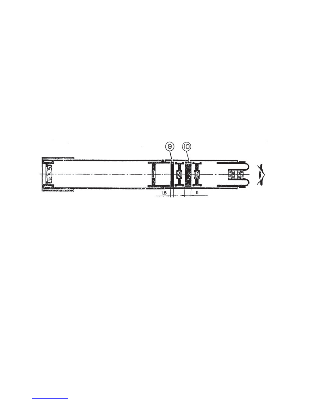
Build the 20X telescope the same way as you built the 10x with the following
changes:
In step 3 insert 1.8mm Spacer (09), instead of Spacer (12).
In step 5 insert 5mm Spacer (10) instead of Spacer (13).
NOTE: If you have difficulty f ocusing either Telescope 10X or 20X, recheck the
position of all parts. You may also adjust the position of Objective Lens (08)
slightly.
T errestrial 10X Telescope
#6 17X Microscope
Microscopes are used for examining very small objects. Microscopes work
very much like telescopes, but have very different focal lengths between the
eyepiece and lens “d”, and between the lens and object “D”.
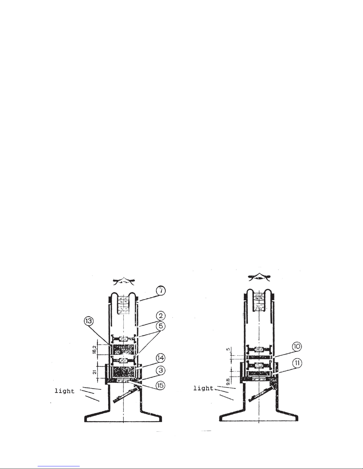
To assemble the 17X microscope:
1. Place the Microscope Base (03) on a clean, hard and flat surface.
2. Place the Drawtube (2) on end on the work table with the number “2” at the
bottom. Insert the 21mm Spacer (14) into the Drawtube and press it all the
way to the bottom. (If Spacer (14) has distinctive rings on one side, insert that
side down.)
3. Insert Inversion Lens (05) into the Drawtube with the marking “5” towards the
Spacer below it.
Page 12
SKU 93233
For technical questions please call 1-800-444-3353
Page 12
4. Then insert 16.2mm Spacer (13).
5. Insert the other Inversion Lens (05) with the “5” marking toward the top.
6. Press all parts into place using the Assembly Rod (16).
7. Insert the Symmetric Lens Eyepiece (07).
8. Remove the 21mm Spacer from the bottom of the Drawtube (02). Spacer (14)
is used only to position the other parts correctly in the Drawtube.
9. Place your specimen to be examined on the Glass Slide (15), and place the
Glass Slide in the Microscope Base (03).
10. Place the Drawtube assembly on the Microscope Base, and focus using the
Eyepiece (07).
1 1. You will need a lot of light to see clearly. Turn the opening on the side of the
Microscope Base toward a strong source of light. The light will be reflected up
through the specimen by the mirror which is mounted in the base.
#7 the 35X microscope
Assemble the 35X microscope the same way as the 17X microscope, except:
In step 2, place the 9.8mm Spacer (11) in the Drawtube (02) instead of Spacer
(14).
In step 4, insert the 5mm Spacer (10) instead of Spacer (13).
the 35X microscope
the 17X microscope
Page 13
SKU 93233
For technical questions please call 1-800-444-3353
Page 13
Hand Held Magnifiers
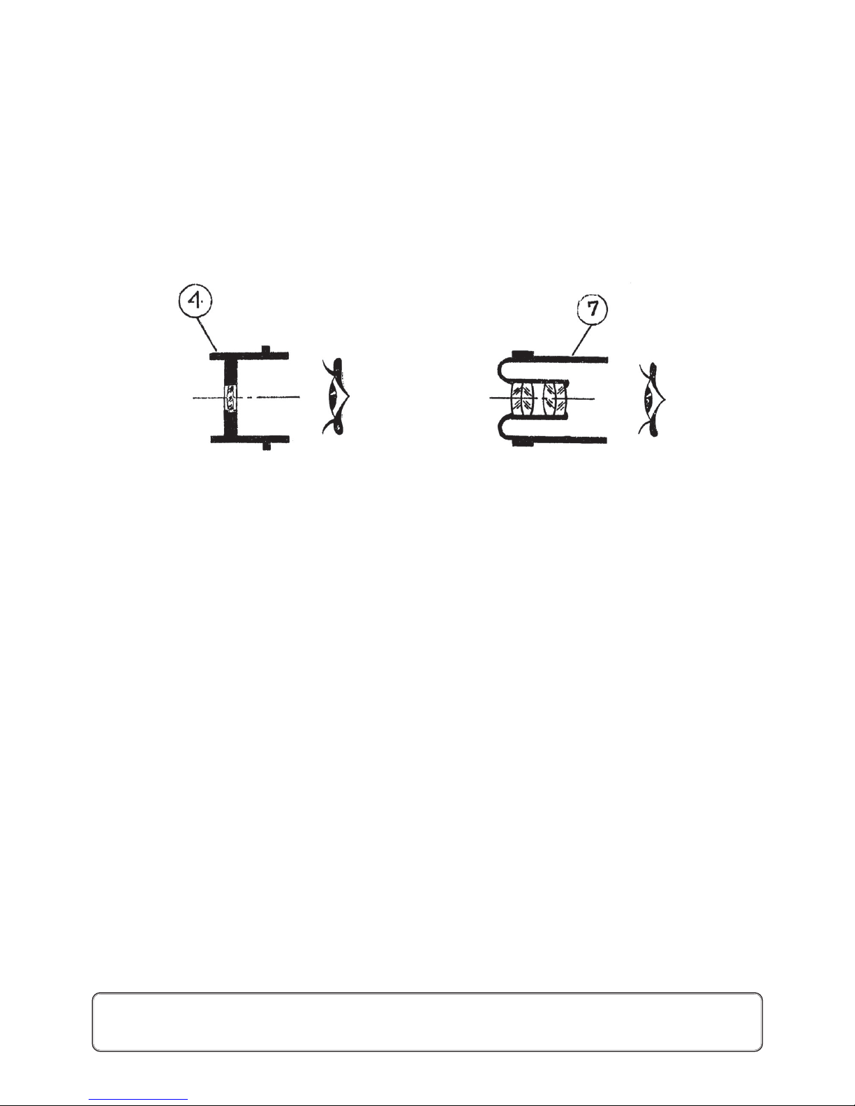
#8 5X Magnifier
The Collecting Lens (04) can be used as a hand held magnifier, with a f ocal
length of 10-15mm.
#9 17X Magnifier
The Symmetric Eyepiece (07) can be used as a hand held magnifier, with a
focal length of 4-8mm.
This optical telescope and microscope kit can be useful to you in learning about
how lenses work both for seeing things v ery far a way, and for seeing very small
things nearby .
As a young scientist, you might think about how lenses work, and how lenses of
various designs and sizes can be used to see objects of interest. There are other
telescope and microscope designs, using mirrors, or electrical impulses or
decaying atoms. You might think of ne w ways to observe very small or very large
objects.
You might also think about which objects it will be interesting to see. What objects
can you think of that have not yet been seen? How large, how far away or how
small is the limit of things that can be seen? Can you think of ways of passing
those limits?
You might also think about how seeing things can answ er other questions. F or
example, Galileo observed the position of se v eral planets relativ e to the Earth and
Sun to learn that the solar system is heliotropic. Recently the United Nations used
pictures of the Earth’s surface tak en by satelite mounted telescopes over time to
show the impact of increased population and climate change on the Earth’s
ecosystems. What things can y ou think of to observe that will help us learn
something?
NOTE: Some parts are listed and shown for illustration purposes only and are not
available individually as replacement parts.
5X Magnifier
17X Magnifier
 Loading...