

Page 1
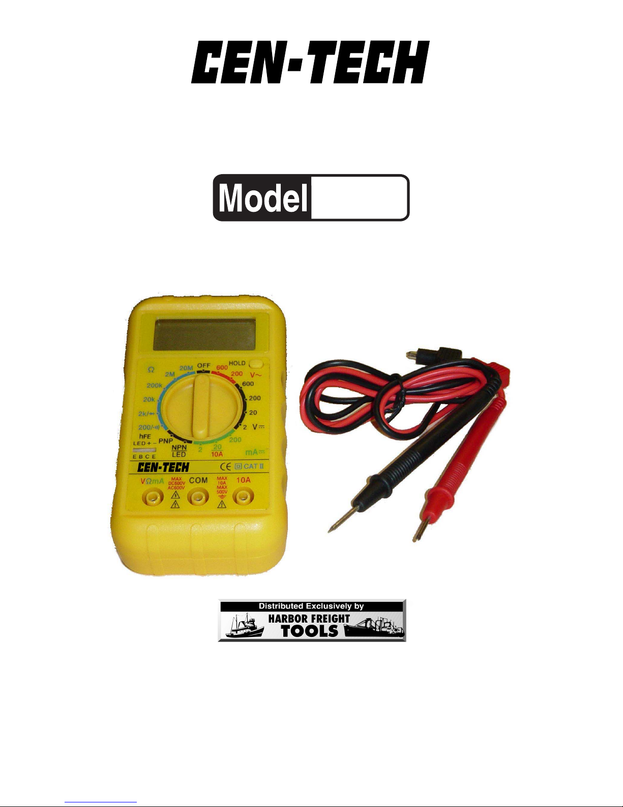
8 FUNCTION DIGIT8 FUNCTION DIGIT
8 FUNCTION DIGIT8 FUNCTION DIGIT
8 FUNCTION DIGIT
AL MULAL MUL
AL MULAL MUL
AL MUL
TIMETERTIMETER
TIMETERTIMETER
TIMETER
OPERATING INSTRUCTIONS
3491 Mission Oaks Blvd., Camarillo, CA 93011
Visit our Web site at http://www .harborfreight.com
Copyright© 2004 by Harbor F reight Tools®. All rights reserved. No portion
of this manual or any artwork contained herein may be reproduced in any
shape or form without the express written consent of Harbor F reight Tools .
For technical questions and replacement parts, please call 1-800-444-3353
®
90939
Page 2

SKU 90939 Page 2
Specifications
Save This Manual
You will need the manual for the safety warnings and
precautions, and operating and maintenance procedures.
Keep y our invoice with this manual. Write the invoice number
on the inside of the front cover. Keep the manual and invoice
in a safe and dry place for future reference.
Safety Warnings and Precautions
WARNING: When using tool, basic safety precautions should always be
followed to reduce the risk of personal injury and damage to
equipment.
Read all instructions before using this tester!
METINOITPIRCSED
ycneuqerFzH005-04
spmACDA01,Am002/02/2:segnaR
ycaruccAtigid1+%2)A01@(;tigid1+%5.1)Am002/02/2@(
egatloVCDV006/002/02/2:segnaR
ycaruccAtigid1+%5.1)V006/002/02@(;tigid1+%5.0)V2@(
egatloVCAV006/002:segnaR
ycaruccAtigid3+%5.2)V006@(;tigid3+%2)zH005-04;V002@(
ecnatsiseR %5.1±mhOM02/M2/K002/K02/K2/002:segnaR
ycaruccA;tigid2+%2)mhO002@(
;tigid2+%5.1)mhOM2,K002/02/2@(
;tigid2+%5.2)mhOM02@(
etaRgnilpmaSdnoceS/semit5.2
noitcetorPdaolrevOesuFV052/A5.gnitcA-tsaFdnaedoiD
erutarepmeTgnitarepOF°401-°23:egnaR
yalpsiD
3
/
4
DCLtigid-4hgih"
yrettaB)dedulcni(V9enO
thgieW.sbl6.
serutaeF
,nottubdlohataD,dnatstroppuS,sdaeLtseT"42
snoitcnufgnitsetDELdna)PNPdnaNPN(rotsisnarT
Page 3

SKU 90939 Page 3
1. Test cable voltages with care. Only use one hand when securing
the tester around the cable to reduce risk of injury in case of electric
shock.
2. Avoid working alone. If an accident happens, an assistant can
bring help.
3. Keep work area clean. Cluttered areas invite injuries.
4. Av oid electrical shock. Use extreme caution when clamping around
uninsulated conductors or bus bars. Prevent body contact with
grounded surfaces such as pipes, radiators, ranges, and cabinet
enclosures when testing voltages.
5. Avoid damaging meter. Use only as specified in this manual.
6. Observe work area conditions. Do not test voltages in damp or
wet locations. Don’t expose to rain. Keep w o rk area well lit.
7. Keep children away. Children must never be allowed in the work
area. Do not let them handle machines, tools, or extension cords.
8. Store idle equipment. When not in use, tools must be stored in a
dry location to inhibit rust. Always lock up tools and keep out of
reach of children.
9. Dress properly. Do not wear loose clothing or jewelry as they can
be caught in moving parts. Protective, electrically nonconductive
clothes and nonskid footwear are recommended when working. W ear
restrictive hair covering to contain long hair.
10. Use eye protection. Always wear ANSI approved impact safety
goggles.
11. Do not overreach. K eep proper f ooting and balance at all times. Do
not reach over or across electrical cables or frames.
12. Maintain tools with care. Ensure multimeter has a fresh battery.
Inspect tool cords periodically and, if damaged, have them repaired
by an authorized technician.
13. Stay alert. Watch what you are doing, use common sense. Do not
operate any tool when you are tired.
14. Check for damaged parts. Before using any tool, any part that
appears damaged should be carefully checked to determine that it
will operate properly and perform its intended function. Check for
alignment and binding of moving parts; any brok en parts or mounting
fixtures; and any other condition that may affect proper operation.
Any part that is damaged should be properly repaired or replaced by
Page 4

SKU 90939 Page 4
Unpacking
When unpacking, make sure the f ollowing parts are included: Digital Clamp
Multimeter, b lack and red Test Leads, hand strap , and carrying case. If any parts are
missing or broken, please call Harbor F reight T ools at the n umber on the cover of this
manual. If an y part of the machine is missing or broken, please call Harbor Freight
Tools at the number on the front cover as soon as possib le.
a qualified technician. Do not use the tool if any switch does not operate
properly.
15. Replacement parts and accessories. When ser vicing, use only
identical replacement parts. Use of any other parts will void the
warranty. Only use accessories intended for use with this tool.
Approved accessories are available from Harbor Freight Tools.
16. Do not operate tool if under the influence of alcohol or drugs.
Read warning labels on prescriptions to determine if your judgment
or reflexes are impaired while taking drugs. If there is any doubt, do
not operate the tool.
17. We recommend that only a licensed electrician work on high-
voltage or other potentially dangerous circuits.
Note: Perf ormance of this tool ma y vary depending on condition of internal
battery.
Warning: The warnings, cautions, and instructions discussed
in this instruction manual cannot cover all possible
conditions and situations that may occur. It must be
understood by the operator that common sense and
caution are factors which cannot be built into this
product, but must be supplied by the oper ator.
Warning: This product contains or produces chemicals,
including lead, known to the State of California to
cause cancer and birth defects (or other
reproductive harm).
(California Health & Safety Code 25249.5 et seq.)
Operation
WARNING: ELECTRICAL SHOCK CAN CAUSE DEATH OR
INJURY. AVOID TOUCHING EXPOSED CONDUCTORS
OF ELECTRICITY.
Additional Multimeter Precautions
1. Do not test voltage on circuits higher than 600 volts.
Page 5
SKU 90939 Page 5
2. Do not test current on circuits
higher than 10 AMPs.
3. Be careful not to apply
voltage to the Test Leads
when they are connected to
the COM (Center)
and Ohm (Left)
Jacks and the
Multimeter is in an
Ohms testing
setting. Damage
can occur to the
multimeter or the
fuse may blow.
4. Do not switch between testing
modes with the multimeter
connected to a circuit.
AC V oltage Measurements
Measure AC conductors carrying up to 600 V A C, 40-500 Hz.
1. T urn the Range Selector Switch to 600V~ setting.
Always start with the highest range if the voltage is unknown.
2. Plug the red lead into the Volt (Left) Jack. Plug the b lack lead into the COM
(Center) Jack.
3. Carefully touch the exposed conductors with the tips of the probes to measure
the voltage (not amperes).
4. Read measurement.
If the voltage is less than 200 volts, set the Range Selector Switch to the
lower range.
5. Optionally , press the Data Hold button to keep the displa y reading the same
after the leads have been removed from the conductors. Press and release
the Data Hold button again to resume normal operation.
6. When testing is complete, remove Test Leads and store with multimeter.
DC Voltage Measurements
Measure DC conductors carrying up to 600 VDC.
1. T urn the Range Selector Switch to 600 V setting.
2. F ollow the directions above under “AC V oltage Measurements”, only use the
DC settings instead.
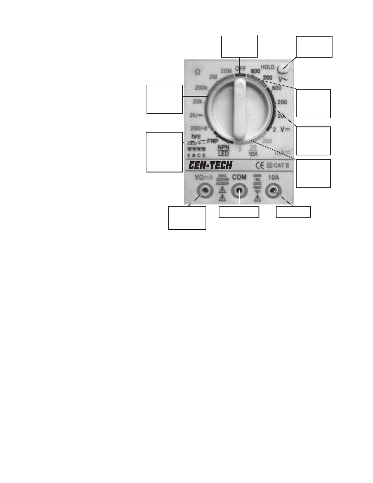
10A JackCOM Jack
Volt/Ohm/
mA Jack
DC AMP
Selection
Area
DC V olt
Selection
Area
AC Volt
Selection
Area
Ohm
Selection
Area
LED/
Transistor
Selection
Area
OFF
Selection
Control Layout
Data Hold
Button
...
_
Page 6

SKU 90939 Page 6
DC Current Measurements
Measure DC conductors carrying up to 10 amperes.
1. T u rn the Range Selector Switch to the position.
Always start with the highest range if the amperage is unknown.
2. Plug the red lead into the 10A (Right) Jack. Plug the black lead into the COM
(Center) Jack.
3. Carefully touch the exposed conductors with the tips of the probes to measure
the amperage.
4. Read measurement.
If the reading is less than .2 AMPs,switch the red lead to the Left AMP Jack
and set the Range Selector Switch to the 200 mA setting.
5. Optionally , press the Data Hold button to keep the displa y reading the same
after the leads have been removed from the conductors. Press and release
the Data Hold button again to resume normal operation.
6. When testing is complete, remove Test Leads and store with multimeter.
Resistance Measurements
Measure circuit resistance up to 20M Ohms.
WARNING: NEVER measure resistance on a circuit with voltage running through it.
1. T urn the Range Selector Switch to the 200 Ω position.
2. Plug the red Test Lead into the Ohms (Left) Jack. Plug the black Test Lead
into the Com (Center) Jack.
Short the Test Leads together. The meter should read “0” Ohms.
3. T ouch the e xposed conductors with the tips of the T est Leads .
4. Read measurement.
If the reading is 1, set the Range Selector Switch to the next higher Ohm (Ω)
position.
5. Optionally , press the Data Hold button to keep the displa y reading the same
after the leads have been removed from the conductors. Press and release
the Data Hold button again to resume normal operation.
Transistor(hFE)/LED Measurements
Test transistors and LEDs to ensure proper function.
1. Turn the Range Selector Switch to the NPN or PNP position depending on
what type of transistor is to be tested. To test a LED use the NPN position.
For Transistors:
a. Insert the transistor pins into the hFE jack according to the EBC (Emitter,
Base, Collector) sequence.
b . The meter will show the approximate hFE value.
...
_
10A
20
Page 7

SKU 90939 Page 7
NOTE: No replacement parts are available for this tool.
Battery/Fuse Replacement
To replace the battery or fuse:
1. Remove the Test Leads from the multimeter.
2. T urn the unit over .
3. Remove the screw using a Philips screwdriver .
4. Remove back cover.
5. Pull battery/fuse out of unit and replace with the same.
(9V battery or .5A/250V fast-acting fuse)
6. Replace cov er and retighten screw .
Measurement Applications
• Household uses – Ver ify and measure current flow and voltage to such
appliances as electric water heaters, fan motors, generators, and pumps.
Measure excessive current flow on circuits in distribution panels which are
tripping circuit breakers. Check for wire continuity or resistance using the
T est Leads and Ohms function.
• Distribution transformers – Measure load on each phase for balance and
for excessive current.
• Motors – Measure starting current, running current, and current imbalance
between phases.
• V ariable speed motor controllers – Measure input and output currents .
Maintenance
1. Wipe unit with a slightly damp cloth using a light detergent. Do not use solvents
or abrasives.
2. Remove battery if not in use for long periods.
3. Store unit in a dry location.
4. Other than the battery and fuse, there are no replaceable parts on this unit.
Repairs should be done by a qualified technician.
For LEDs:
a. Insert the LED’s pins into the + and - signs into the hFE jack.
b . A working LED should shine brightly . The meter reading is unimportant.
c. This function is only used to test an LED rated at 1.5~3V in regards to
brightness.
Page 8
Page 9
 Loading...