

Page 1

20 RANGE ANALOG MUL20 RANGE ANALOG MUL
20 RANGE ANALOG MUL20 RANGE ANALOG MUL
20 RANGE ANALOG MUL
TIMETERTIMETER
TIMETERTIMETER
TIMETER
OPERATING INSTRUCTIONS
3491 Mission Oaks Blvd., Camarillo, CA 93011
Visit our Web site at http://www .harborfreight.com
Copyright© 2004 by Harbor F reight Tools®. All rights reserved. No portion
of this manual or any artwork contained herein may be reproduced in any
shape or form without the express written consent of Harbor F reight Tools .
For technical questions and replacement parts, please call 1-800-444-3353
®
90926
Page 2

SKU 90926 Page 2
For technical questions, please call 1-800-444-3353.
Specifications
Save This Manual
You will need the manual f or the safety warnings and precautions, and operating
and maintenance procedures. K eep your in voice with this man ual. Write the in voice
number on the inside of the front cov er. Keep the man ual and invoice in a safe and dry
place for future reference.
Safety Warnings and Precautions
WARNING: When using tool, basic saf ety precautions should alwa ys be f ollow ed to
reduce the risk of personal injury and damage to equipment.
Read all instructions before using this tester!
1. Av oid working alone. If an accident happens , an assistant can bring help.
2. Keep work area clean. Cluttered areas invite injuries.
3. Av oid electrical shock. Use extreme caution when working around uninsu-
lated conductors or bus bars. Prevent body contact with grounded surfaces
noitcnuFycaruccA/egnaR
segnaRegatloVCA
*DSF%4±V052/05/01
DSF%5±V0001
segnaRegatloVCD
DSF%3±V052/05/01/5.2/5.0/1.0
DSF%4±V0001
segnaRegarepmACD
05 µ )Vm052:egatloVporD(DSF%3±Am052/Am52/Am5.2/A
DSF%4±A01
segnaRecnatsiseR
K01x/K1x/01x/1x
Ω
%5±
serutaeFrehtO
rotsisnarT,tseTytiunitnoC,tseTyrettaBV9dna)"AA"(V5.1
oreZdna,tsujdAoreZ,tseTDELdna Ω tsujdA
noitcelfeDelacS-lluF="DSF"*
METINOITPIRCSED
noitcetorPdaolrevOedoiddnaesufV052,A5.0
ycneuqerFzH06
yalpsiDtnemevomlacinahcemortcele,golanA
yrettaByrettaBV9enOdnaseirettaB"AA"owT
erutarepmeTgnitarepOF°401ot°23
erutarepmeTegarotSF°221ot°41
thgieWsbl7.0
seirosseccA(deR + (kcalBdna) - sdaeLtseT"42)
Page 3

SKU 90926 Page 3
For technical questions, please call 1-800-444-3353.
such as pipes, radiators, ranges, and cabinet enclosures when testing voltages.
4. Av oid damaging meter. Use only as specified in this manual.
5. Observe work area conditions. Do not test circuits in damp or wet locations. Don’t e xpose to rain. K eep work area well lit.
6. Keep children a way. Children must ne ver be allowed in the work area. Do
not let them handle machines, tools, or extensions cords.
7. Store idle equipment. When not in use, tools must be stored in a dry
location to inhibit rust. Always lock up tools and keep out of reach of children.
8. Dress properly. Do not wear jewelry as an accidental brush may cause a
short circuit causing electric shock or severe burns. Protective, electrically
nonconductive clothes and nonskid rubber-soled footwear are recommended
when working. W ear restrictive hair covering to contain long hair .
9. Use eye protection. Always wear ANSI approved impact safety goggles.
10. Do not overreach. Keep proper footing and balance at all times. Do not
reach over or across electrical cables or frames.
11. Maintain tools with care. Ensure multimeter has a fresh battery. Inspect
tool cords periodically and, if damaged, have them repaired by an authorized
technician.
12. Stay alert. W atch what y ou are doing, use common sense. Do not operate
any tool when you are tired.
13. Check for damaged parts. Before using any tool, any part that appears
damaged should be carefully checked to determine that it will operate properly and perform its intended function. Check for alignment and binding of
moving parts; any brok en parts or mounting fixtures; and any other condition
that may aff ect proper operation. Any part that is damaged should be properly repaired or replaced by a qualified technician. Do not use the tool if any
switch does not operate properly.
14. Accessories. Only use accessories intended for use with this tool. Approved
accessories are availab le from Harbor Freight Tools.
15. Do not operate tool if under the influence of alcohol or drugs. Read
warning labels on prescriptions to determine if your judgment or reflexes are
impaired while taking drugs. If there is any doubt, do not operate the tool.
16. People with pacemakers should consult their physician(s) before using
this product. Electromagnetic fields in close proximity to a heart pacemaker could cause interference to or f ailure of the pacemaker .
In addition, caution is necessary when near the coil, spark plug cables,
or distributor of a running engine. The engine should always be off if
adjustments are to be made to the distributor .
Page 4
SKU 90926 Page 4
For technical questions, please call 1-800-444-3353.
Unpacking
When unpacking, mak e sure that the Analog Multimeter, and both T est Leads
are included. If an y parts are missing or broken, please call Harbor F reight Tools at
the number on the cover of this manual.
Multimeter Additional Safety W arnings
1. Do not test voltage on circuits higher than 1,000 volts.
2. Do not test current on AC circuits or on DC circuits higher than 10 amps.
3. Be careful not to apply voltage to the Test Leads when the meter is in an
ohms testing position. Damage can occur to the multimeter.
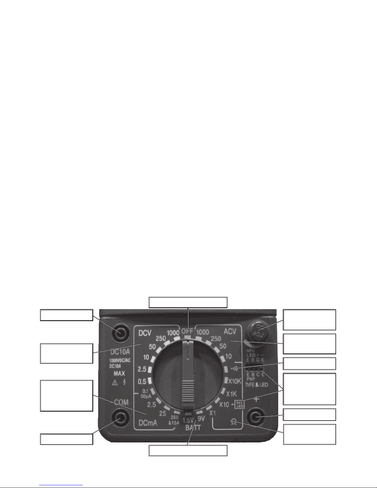
Control Layout
Refer to this diagram while following the directions in the
Operation
section.
DC 10A Jack
-COM Jack
+ Jack
LED/Transistor
Selection and
Jack
DC current
Selection Area
(mA)
Ohm Selection
Area
AC Volt
Selection Area
Ohm Zero
Adjust
OFF Selection
DC V olt
Selection Area
Continuity Test
Battery Selection Area
Warning: The w arnings, cautions , and instructions discussed in this instruction man ual
cannot cover all possible conditions and situations that may occur. It must
be understood by the operator that common sense and caution are factors
which cannot be built into this product, but m ust be supplied by the operator .
Page 5
SKU 90926 Page 5
For technical questions, please call 1-800-444-3353.
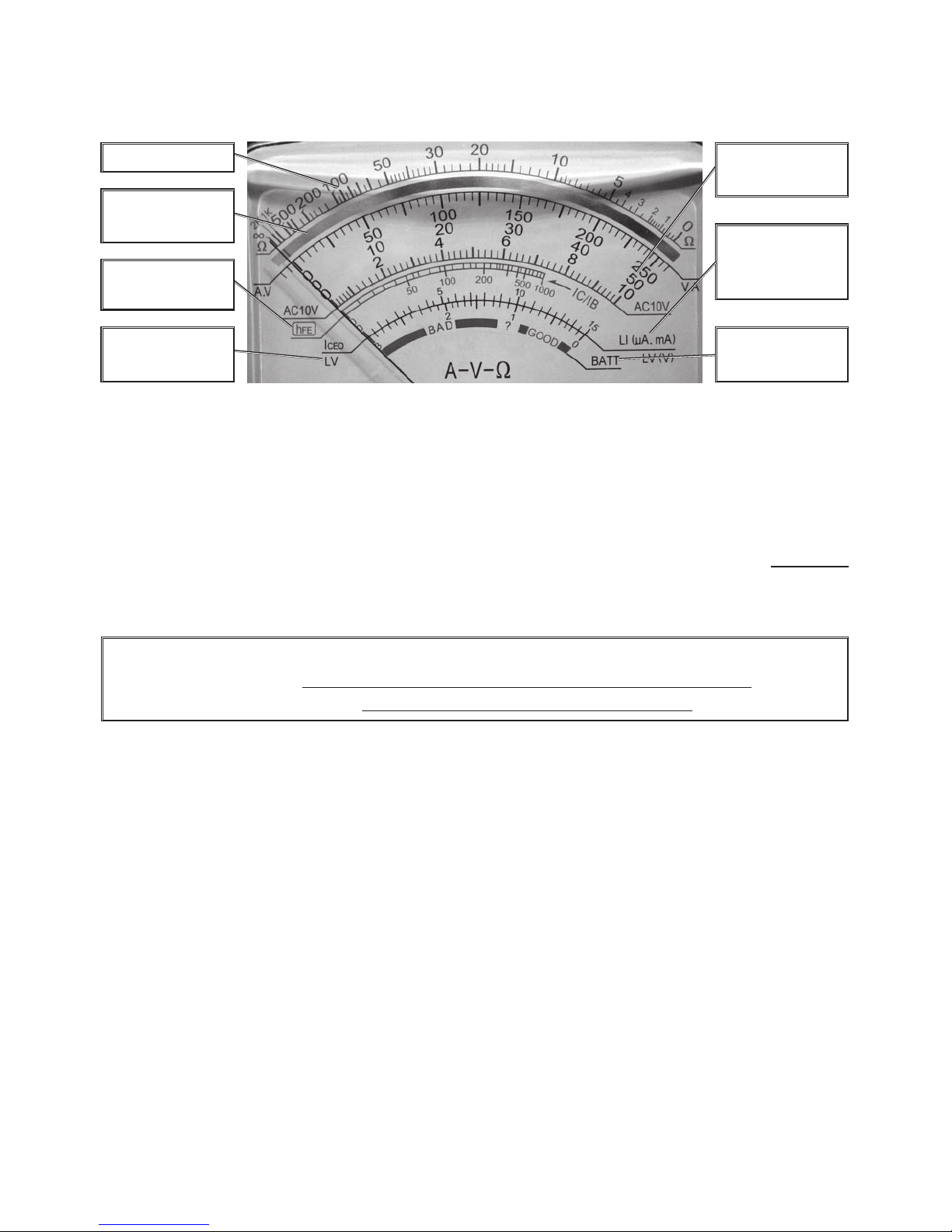
Reading the Scale
Refer to this diagram while following the directions in the
Operation
section.
The Accuracy Mirror
The Accuracy Mirror is used to insure that the meter’ s pointer is being read
straight, ensuring accuracy . Simply make sure that the meter is angled so that, when
reading it, the reflection of the pointer is hidden under the pointer . The pointer abov e
is being viewed at an angle, so the reflection is visible.
Note: Although on some meters a decibel (db) scale is shown, this meter does not
have available the equipment to test sound decibel levels.
Ohm Scale
Amperage/
Voltage Scales
Transistor
Leakage
Current (lceo)
Current Gain
Scale (hFE)
Forward
Voltage Drop
Battery
Test Area
Accuracy
Mirror
Warning: Electric shock can cause DEA TH or SEVERE PERSONAL INJUR Y.
Never touch exposed conductors of electricity with
fingers, hands or any other body part.
Operation
DC V olta ge Measurements
Measure DC voltages up to 1,000 DCV.
1. T urn the Range Selector Switch to 1000 DCV.
Always start with the highest range if the voltage is unknown.
2. Plug the red lead into the + Jack. Plug the black lead into the -Com Jack.
3. Carefully touch the appropriate exposed conductors with the tips of the probes
to measure the voltage (not amperes).
4. Read measurement. If the needle moves in the opposite direction, then the
probes are connected incorrectly . Rev erse the probes’ locations.
If the voltage is less than 250 volts, set the Range Selector Switch to the
next lower range until the meter pointer is mid-range on the scale.
5. When testing is complete, remov e Test Leads and store them and the meter
in a safe, dry location.
Page 6

SKU 90926 Page 6
For technical questions, please call 1-800-444-3353.
AC V oltage Measurements
Measure AC v oltages up to 1000 V.
1. Turn the Range Selector Switch to 1000 ACV.
Always start with the highest range if the voltage is unknown.
2. Follo w the directions on the previous page under
DC V oltage Measurements
(except for the polarity directions, they are unnecessary with AC).
DC Current Measurements
Measure DC conductors carrying up to 10 A.
1. Turn the Range Selector Switch to the 250 DCmA & 10A position. Plug the
red lead into the + Jack. Plug the black lead into the DC10A Jack.
Note: Testing current should ONLY be done in series, with the circuit con-
nected and current flowing.
Note: The DC10A jack is NO T fuse protected. Onl y test circuits known to be 10
amps or less.
3. Carefully connect the test leads to the circuit or the load being tested.
4. Read measurement. If the Amperage is less than .25A (250mA), disconnect
the leads from the circuit first, then unplug the black lead and plug it into the
-COM Jack. If the Amperage is less than 25mA, set the Range Selector
Switch to the next lower range until the meter pointer is mid-range on the
scale.
5. When testing is complete, remov e Test Leads and store them and the meter
in a safe, dry location.
Resistance (Ohm) Measurements
Circuit resistance can be measured on ranges from meter reading times 1 to meter
reading times 10,000.
Note: Testing resistance should ONLY be done with the power to the cir cuit
disconnected. T est to make sure no voltage is present fir st. If v oltage is
applied while testing, disconnect the tester immediately , otherwise the
fuse may blow and the tester may be damaged-see
Fuse Replacement
under
Maintenance
.
1. Turn the Range Selector Switch to the Ohm testing position (between x1
ΩΩ
ΩΩ
Ω
and x10K
ΩΩ
ΩΩ
Ω) you will be measuring at.
2. Plug the red lead into the + Jack. Plug the black lead into the -Com Jack.
3. Short the Test Leads together . The meter should read “0” Ohms.
4. If the meter does not read “0” Ohms, the ohmmeter needs to be calibrated to
enable accurate measurements.
a. With the test leads held together, adjust the Ohm Zero Adjust Knob until
the meter’s pointer aligns on “0”.
Page 7

SKU 90926 Page 7
For technical questions, please call 1-800-444-3353.
b . If the pointer cannot be adjusted far enough to align with zero , the battery
needs to be replaced-see
Battery Replacement
under
Maintenance
.
5. Touch the exposed conductors with the tips of the Test Leads.
If, by chance, a voltage is present, the fuse may blow-see
Fuse Replace-
ment
under
Maintenance
. Immediately remove the Test Leads from the
conductors.
6. Read measurement.
If the resistance measured is off the scale, move the Range Selector Switch
to a higher Ohms position.
7. Continuity Testing: Turn the Range Selector Switch to Continuity Test. This
test is a type of Ohms test. When the wiring between the 2 test leads has
low resistance (less than 50
ΩΩ
ΩΩ
Ω) then the buzzer will sound. This is useful f or
detecting breaks in wiring.
8. When testing is complete, remov e Test Leads and store them and the meter
in a safe, dry location.
Transistor/LED Measurements
1. Turn the Range Selector Switch to the x10 Ω position.
For Transistors:
a. Insert the transistor pins into the appropriate hFE jack (either NPN or PNP)
according to the EBC (Emitter, Base , Collector) sequence.
b . The meter will show the approximate hFE value.
c. With the Base terminal disconnected, the meter will show the lceo (leak)
value.
For LEDs:
a. Insert the LED’s pins into the + and - signs into the hFE jack (the two termi-
nals farthest right on the top (NPN) row).
b . A working LED should shine brightly . The meter reading is unimportant.
c. This function is only used to test an LED rated at 1.5~3V in regards to
brightness.
2. Remov e Test Leads and store them and the meter in a saf e, dry location.
Battery Testing
1. Turn the Range Selector Switch to either the BATT 9V or 1.5V (“AA” Size
Battery) setting.
2. Plug the red lead into the + Jack. Plug the black lead into the -Com Jack.
3. Connect the red test lead to the positive end of the battery and the black
lead to the negative.
4. Read measurement. When testing is complete, remov e Test Leads and store
them and the meter in a safe, dry location.
Page 8
SKU 90926 Page 8
For technical questions, please call 1-800-444-3353.
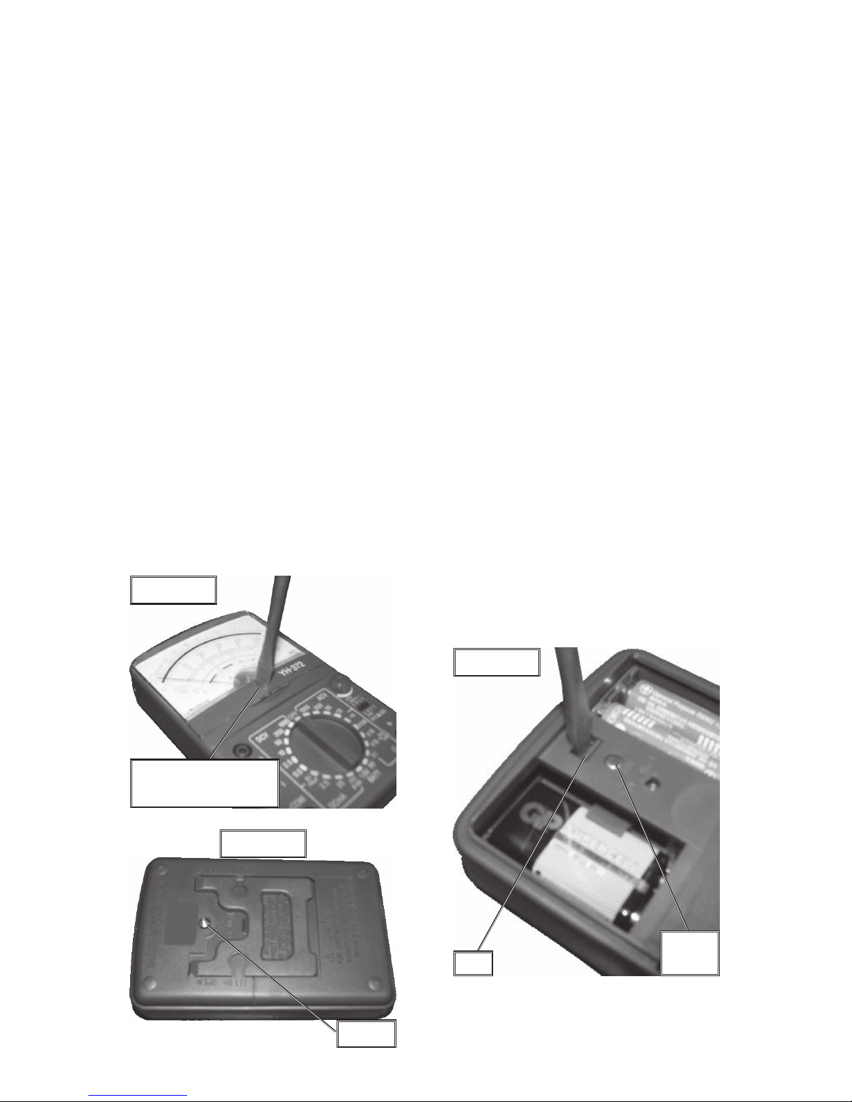
6. Meter Pointer Calibration
Over time, it ma y become necessary to adjust the meter pointer to align on “0.”
a. Remove the Test Leads from the m ultimeter.
b. Using a small standard screwdriver, place it on the small Meter Zero
Adjustment screw right below the center of the dial. See
Figure A
.
c. Turn screw slightly until the meter pointer aligns on “0.”
Figure C
Tab
Spare
Fuse
Figure B
Screw
Meter Zero
Adjustment Screw
Figure A
Maintenance
1. Wipe unit with a damp cloth using a light detergent. Do not use solvents or
abrasives. Allow the unit to dry completely before use or storage.
2. Remove batteries if not in use for long periods.
4. Store unit in a dry location out of children’s reach.
5. Aside from the fuse and batteries, there are no user replaceable parts on this
unit. REP AIRS SHOULD BE DONE ONL Y BY A Q UALIFIED TECHNICIAN.
Page 9
SKU 90926 Page 9
For technical questions, please call 1-800-444-3353.
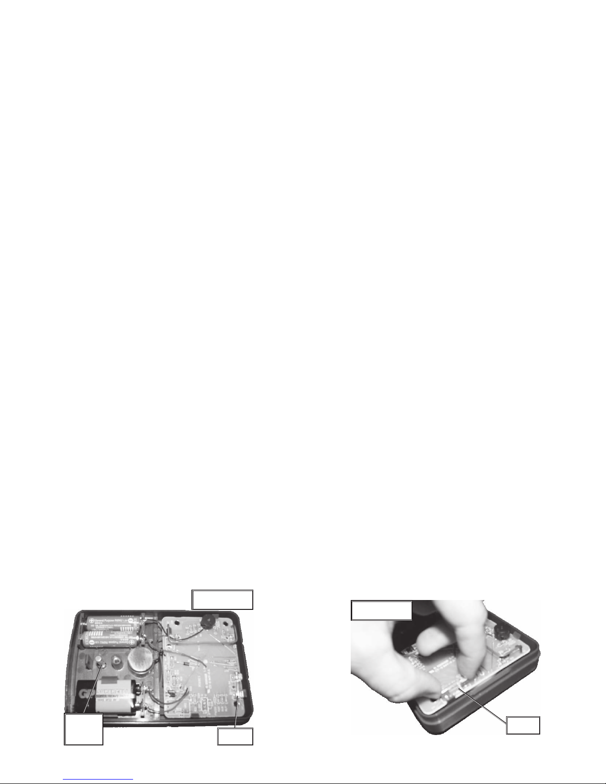
Figure D
Fuse
Spare
Fuse
Figure E
Fuse
7. Battery Replacement
If the Ohms cannot be adjusted to indicate zero, one or more of the batteries need
replacement.
a. Remov e the Test Leads from the multimeter .
b. Turn the unit over to show its bac k.
c. Remove the screw indicated in
Figure B
(page 8) using a Philips screw-
driver.
d. Slide the battery cover up and off of the back.
e. Using a regular screwdriver, gently hold the tab between the batteries
back while opening the back co ver . See
Figure C
, previous page.
f. Remove the batteries and replace, being sure to align the new batteries
properly.
g. Snap the back cover on, slide on the battery cover, and retighten the
screw.
8. Fuse Replacement
If the multimeter is exposed to excessive current, misused, or dropped, the fuse
may become blown. Check the fuse if the meter does not work for no apparent
reason.
a. Follow directions a through e under
Battery Replacement
to remove the
back cover.
b. Note the location of the spare fuse in
Figure C
, page 8 and
Figure D
,
below.
c. Carefully examine the fuse in the meter. If the thin wire in the tube is
broken, the fuse is blown and needs to be replaced. See
Figures D
and
E
.
Warning: ONLY replace the fuse in this meter with another 0.5A, 250V
fuse. Using the wrong fuse or using another material or object
instead of a fuse is very dangerous and may cause a fire.
d. After replacing the fuse, close the meter .
Page 10
SKU 90926 Page 10
For technical questions, please call 1-800-444-3353.
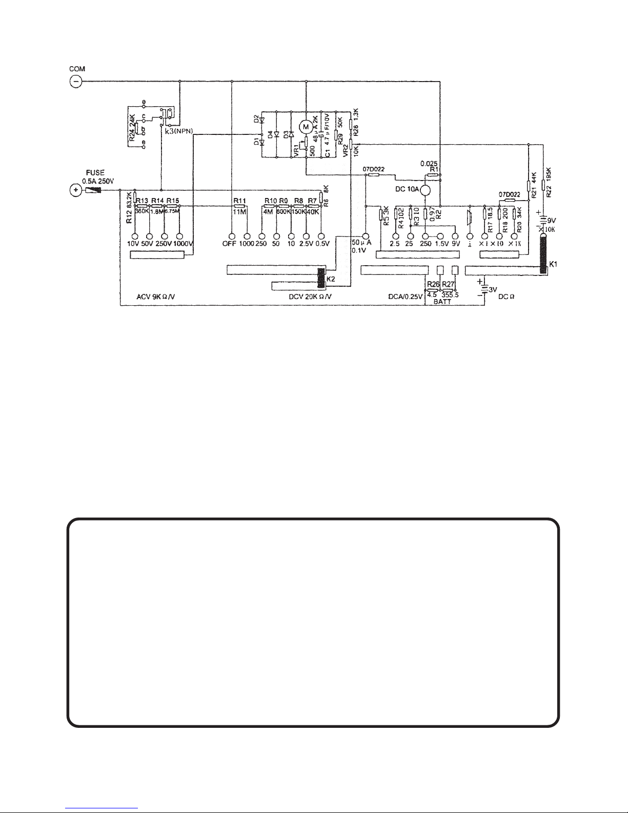
PLEASE READ THE FOLLOWING CAREFULLY
THE MANUF ACTURER AND/OR DISTRIBU TOR HAS PRO VIDED THE
WIRING DIAGRAM IN THIS MANUAL AS A REFERENCE T OOL ONL Y . NEITHER
THE MANUF ACTURER OR DISTRIBUT OR MAKES ANY REPRESENT A TION OR
W ARRANTY OF ANY KIND TO THE BUYER THA T HE OR SHE IS QUALIFIED TO
MAKE ANY REP AIRS TO THE PR ODUCT , OR THAT HE OR SHE IS QU ALIFIED
TO REPLA CE ANY P ARTS OF THE PR ODUCT . IN F A CT , THE MANUFA CTURER
AND/OR DISTRIBUT OR EXPRESSL Y ST A TES THA T ALL REPAIRS AND P ARTS
REPLACEMENTS SHOULD BE UNDER T AKEN BY CERTIFIED AND LICENSED
TECHNICIANS, AND NO T BY THE BUYER. THE BUYER ASSUMES ALL RISK
AND LIABILITY ARISING OUT OF HIS OR HER REPAIRS TO THE ORIGINAL
PRODUCT OR REPLACEMENT PARTS THERETO, OR ARISING OUT OF HIS
OR HER INST ALLA TION OF REPLA CEMENT P ARTS THERETO .
Wiring Diagram
Aside from the fuse and batteries, there are no
user replaceable parts on this unit.
 Loading...