

Page 1
Page 2
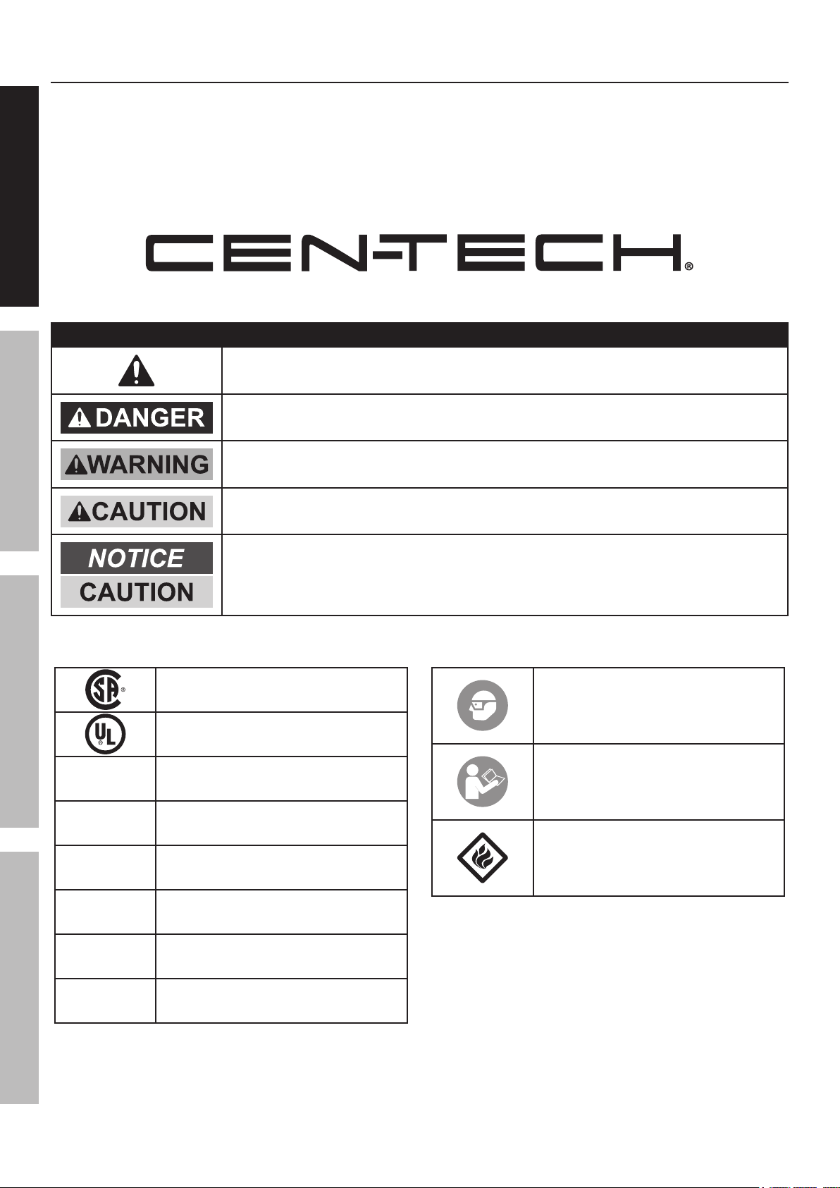
Table of Contents
Safety ......................................................... 2
Specifications ............................................. 4
Setup .......................................................... 5
SAFETY OPERATION MAINTENANCESETUP
Operation .................................................... 8
This is the safety alert symbol. It is used to alert you to potential personal injury hazards.
Maintenance .............................................. 10
Parts List and Diagram .............................. 11
Warranty .................................................... 12
WARNING SYMBOLS AND DEFINITIONS
Obey all safety messages that follow this symbol to avoid possible injury or death.
Indicates a hazardous situation which, if not avoided,
will result in death or serious injury.
Indicates a hazardous situation which, if not avoided,
could result in death or serious injury.
Indicates a hazardous situation which, if not avoided,
could result in minor or moderate injury.
V
~
A
CCA
RC
Addresses practices not related to personal injury.
Canadian Standards Association
Underwriters Laboratories, Inc.
Volts
Alternating Current
Amperes
Cold Cranking Amps
Reserve Capacity
WARNING marking
concerning Risk of Eye Injury.
Wear ANSI-approved
splash-resistant safety goggles.
Read the manual before
set-up and/or use.
WARNING marking
concerning Risk of Fire.
Follow connection procedure.
Ah
Page 2 For technical questions, please call 1-800-444-3353. Item 60666
Ampere-hours
Page 3
Safety Warnings and Precautions
General Safety Warnings
Read all safety warnings and instructions.
Failure to follow the warnings and instructions may result in electric shock, fire and/or serious injury.
Save all warnings and instructions for future reference.
WARNING – RISK OF EXPLOSIVE GASES.
Working in vicinity of a lead-acid battery is
dangerous. Batteries generate explosive gases
during normal battery operation. For this reason,
it is of utmost importance that you follow the
instructions each time you use the Power Pack.
To reduce risk of battery explosion, follow these
instructions and those published by battery
manufacturer and manufacturer of any equipment you
intend to use in vicinity of battery. Review cautionary
marking on these products and on engine.
Work Area Safety
SAFETYOPERATIONMAINTENANCE SETUP
1. Keep work area clean and well lit.
Cluttered or dark areas invite accidents.
2. Do not operate Power Pack in explosive
atmospheres, such as in the presence of
flammable liquids, gases or dust. The Power Pack
can create sparks which may ignite the dust or fumes.
Electrical Safety
1. Do not drop a metal tool onto battery. It
might spark or short-circuit battery or other
electrical part that may cause explosion.
2. Do not operate if Power Pack has received a
sharp blow, been dropped, or otherwise damaged
in any way; take it to a qualified technician.
3. Do not leave Power Pack unattended
while switched on. It could result
in fire and property damage.
4. Do not expose to rain or wet conditions.
Water entering the Power Pack will
increase the risk of electric shock.
3. Keep children and bystanders away
while operating the Power Pack.
Distractions can cause you to lose control.
4. Store idle equipment. Always lock up tools
and keep out of reach of children.
5. Do not use an extension cord with this item.
6. Use of an attachment not recommended or
sold by the manufacturer may result in a risk
of fire, electric shock, or injury to persons.
7. To reduce risk of damage to electric plug
and cord, pull by plug rather than cord
when disconnecting the Adapter.
8. Do not operate with damaged cord or plug.
Replace the cord or plug immediately.
Personal Safety
1. Wear ANSI-approved splash-resistant
safety goggles and heavy-duty
rubber work gloves whenever
connecting, disconnecting, or
working near battery. Battery acid
can cause permanent blindness.
Avoid touching eyes while working near battery.
2. Do not use Power Pack while you are tired
or under the influence of drugs, alcohol
or medication. A moment of inattention
while operating Power Pack may
result in serious personal injury.
3. NEVER smoke or allow a spark or flame
in vicinity of battery or engine.
4. If battery acid contacts skin or clothing,
wash immediately with soap and water.
If acid enters eye, immediately flood eye with
running cold water for at least 10 minutes
and get medical attention immediately.
5. Remove personal metal items such as rings,
bracelets, necklaces, and watches when working
with a lead-acid battery. A lead-acid battery can
produce a short-circuit current high enough to weld
a ring or the like to metal, causing a severe burn.
6. People with pacemakers should consult their
physician(s) before use. Electromagnetic fields in
close proximity to heart pacemaker could cause
pacemaker interference or pacemaker failure.
Page 3For technical questions, please call 1-800-444-3353.Item 60666
Page 4
Service
Have your Power Pack serviced by a qualified repair person using only identical replacement parts.
This will ensure that the safety of the Power Pack is maintained.
Power Pack Safety Warnings
SAFETY OPERATION MAINTENANCESETUP
1. Lead-acid batteries generate hydrogen gas when
charging. Hydrogen gas is explosive. Only use
the Jump-Start system in a well-ventilated area.
2. Jump Starting A Vehicle
a. Use the Power Pack for jump starting
a LEAD-ACID battery only.
b. For emergency use only. Do not use the Power
Pack as a replacement for a vehicle battery.
c. Be sure area around battery is well ventilated
while battery is being jump started.
d. NEVER jump start a frozen battery.
e. Do not attempt to jump start a vehicle with
a non-rechargeable or defective battery.
f. Study all battery manufacturer’s specific
precautions for jump starting.
g. DO NOT TOUCH POSITIVE AND NEGATIVE
BATTERY CLAMPS TOGETHER.
h. Unplug the Power Pack from its Adapter
before connecting its cables to a battery.
i. Connect and disconnect battery cable
clamps only after setting any Jump Starter
switches to OFF position.
j. Connect cables to proper polarities. Connect
black cable to negative body ground and
red cable to positive battery terminal.
k. Locate Power Pack as far away from
battery as battery cables permit.
3. Maintain labels and nameplates on the Power Pack.
These carry important safety information.
If unreadable or missing, contact
Harbor Freight Tools for a replacement.
4. WARNING: This product contains lead, which is a
chemical known to the State of California to cause
cancer and birth defects or other reproductive harm.
(California Health & Safety Code § 25249.5, et seq.)
5. WARNING: This product contains or, when
used, produces a chemical known to the
State of California to cause cancer and birth
defects or other reproductive harm. (California
Health & Safety Code § 25249.5, et seq.)
6. WARNING: Handling the cord on this product will
expose you to lead, a chemical known to the State of
California to cause cancer, and birth defects or other
reproductive harm. Wash hands after handling.
(California Health & Safety Code § 25249.5, et seq.)
7. The warnings, precautions, and instructions
discussed in this instruction manual cannot
cover all possible conditions and situations
that may occur. It must be understood by the
operator that common sense and caution are
factors which cannot be built into this product,
but must be supplied by the operator.
SAVE THESE INSTRUCTIONS.
Specifications
Cold Cranking Amps 360
Peak Amps 900
Battery 12V, 18Ah, Sealed Lead-Acid
Battery Cables 16″ L
Maximum Air Pressure 240 PSI
Functions: 12 Volt Jump-Starter, Air Compressor,
12VDC Power Supply, and Work Light
Specification
Page 4 For technical questions, please call 1-800-444-3353. Item 60666
Page 5
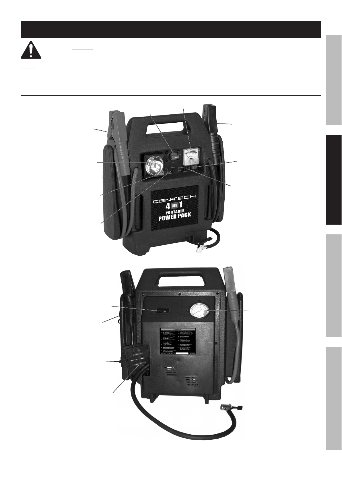
Setup - Before Use:
Read the ENTIRE IMPORTANT SAFETY INSTRUCTIONS section at the beginning of this
manual including all text under subheadings therein before setup or use of this product.
Note: For additional information regarding the parts listed in the following pages,
refer to Parts List and Diagram on page 11.
Functions
Positive
Battery
Cable
Work
Light
Charging
Indicator
Light
12VDC
Charging
Input
Clamp
Power Switch
SAFETYOPERATIONMAINTENANCE SETUP
Voltmeter
Negative
Battery
Cable
Battery
Test Button
Work Light
Switch
Air Compressor
Switch
12VDC
Outlet
120VAC
Charging
Input
Air Hose
Comparment
Air
Pressure
Gauge
Air
Hose
Figure A
Page 5For technical questions, please call 1-800-444-3353.Item 60666
Page 6
Charging the Power Pack
WARNING! Always charge on a non-flammable surface.
Press and hold the Battery Test Button on the front
of the unit to check the battery power level.
SAFETY OPERATION MAINTENANCESETUP
a. 13-15 volts is ready for use.
b. 12 volts needs to be charged.
c. Less than 12 volts should be
charged immediately.
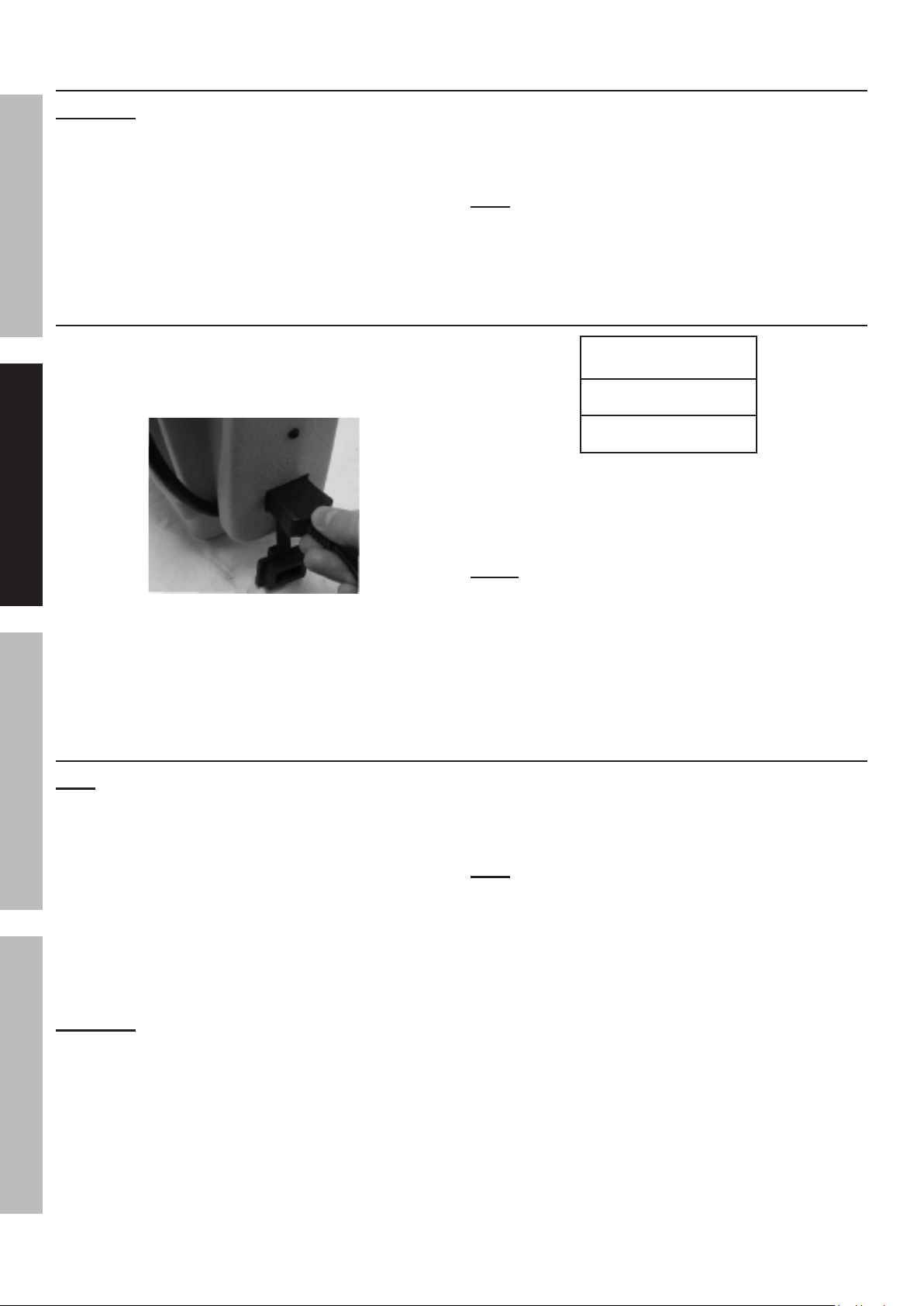
120VAC Charging
1. Plug the 120VAC Adapter into a 2 or 3-prong outlet.
2. Slide the Adapter socket on the 120VAC Charging
Input on the side of the Power Pack.
Figure B
(See Figure B.)
Turn the Clamp Power Switch on front
of unit to the OFF position.
Note: Before initial use, completely charge the Power
Pack. The Charging Indicator Light will illuminate
when the unit is charging and will automatically
shut off when the Power Pack is fully charged.
Approximate
AC Charge Time
Initial Charge:
48 hours
Recharge:
34 hours
Figure C
3. The Voltmeter must be checked periodically
when charging, and the Power Pack must
be unplugged when it is fully charged.
NOTE: FAILURE TO RECHARGE POWER
PACK WILL VOID WARRANTY.
4. Recharge:
a. When voltage drops to 12 volts.
b. After each Jump-Start.
c. Once a month.
Emergency 12VDC Charging
Note: The Power Pack can be charged from a vehicle’s 12VDC power supply. This method of
recharging will not charge the unit as fully as when using the 120VAC Charging method.
This recharging method may also shorten the life of the Power Pack’s
Battery, so only use this method in an emergency situation.
1. Plug the 12VDC Adapter into the
vehicle’s 12VDC outlet.
2. Plug the other end of Adapter into the 12VDC
Charging Input on the front of the Power Pack..
3. Start the vehicle’s engine to allow its
alternator to charge the Power Pack.
WARNING! Vehicle must be outdoors to
prevent build up of deadly exhaust gases.
Note: The vehicle’s battery alone will NOT charge
the Jump Starter, the vehicle’s engine needs to run.
4. Charge the Power Pack for the minimal
time needed to at least 14 volts.
5. The Voltmeter must be checked periodically
when charging, and the Power Pack must
be unplugged when it is fully charged.
Page 6 For technical questions, please call 1-800-444-3353. Item 60666
Page 7
DC Appliance Compatibility
The Power Pack can run/charge 12VDC
auto, RV, marine, or other portable
appliances that draw 10 amps or less.
The lower the amount of watts the appliance
draws, the longer the Power Pack can power
it before needing to be recharged.
Calculate the total wattage needed to run the
appliance before operation. You do not need
to calculate startup or surge wattages.
To calculate the size of the load you plan to use
with the Power Pack, use the following formula:
Amps x Volts = Watts
For example, if you use an appliance whose
running amps total 7 amps, you will need 84
watts of power (7 amps x 12V = 84 Watts) to
run the items. This figure is within the capacity
of the unit (10 amps x 12V = 120 Watts).
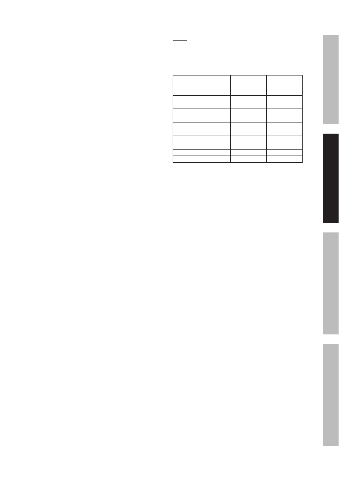
Note: Use this chart as a guideline only.
The actual power usage may vary based on the
model or brand of the appliance. Check the actual
wattage of your appliances and calculate the
amount of power needed to run/charge them.
Estimated
Appliance
Fluorescent Light,
Cell Phone Charger
Radio, Fan,
Depth Finder
Video Recorder/
Player, Spotlight
Small Power Tool,
Bilge Pump
Electric Cooler 48 3
Air Compressor 80 2
Power
(watts)
4 50
9 26
15 14
24 8
Figure D
Estimated
Use (hours)
SAFETYOPERATIONMAINTENANCE SETUP
Page 7For technical questions, please call 1-800-444-3353.Item 60666
Page 8
Operating Instructions
Using the Work Light
SAFETY OPERATION MAINTENANCESETUP
1. To turn the Work Light on, push the Work
Lights Switch to the “I” (ON) position.
Jump Starting a Vehicle
2. To turn the Work Light off, push the Work
Lights Switch to the “O” (OFF) position.
Note: Read the vehicle owner’s manual pertaining
to jump starting prior to using the Power Pack.
1. Press the Battery Test Button to verify that the
Power Pack is fully charged. Recharge as needed,
following the instructions in the Setup section under
“Charging the Power Pack” on page 6.
2. Turn off the vehicle ignition switch and all
accessories (lights, radio, climate control, etc.).
3. Turn all switches on the Power Pack
to their OFF positions. You may leave
the Work Light on if needed.
WARNING! DO NOT TOUCH POSITIVE AND
NEGATIVE BATTERY CLAMPS TOGETHER.
3. Connect the red Positive Battery Cable to
vehicle’s positive battery terminal. Connect
the black Negative Battery Cable to a nonmoving metal part of the vehicle.
Using the Air Compressor
1. Press the Battery Test Button to verify that the
Power Pack is fully charged. Recharge as needed,
following the instructions in the Setup section under
“Charging the Power Pack” on page 6.
WARNING! DO NOT CONNECT TO THE
NEGATIVE TERMINAL OF THE BATTERY.
4. When the correct connection has been made, turn
the Clamp Power Switch to the ON position.
5. WAIT FIVE MINUTES, then start the
vehicle. If the vehicle does not start, wait an
additional 3 minutes before trying again.
WARNING! THE VEHICLE WILL NOT START IF
YOU DO NOT WAIT AT LEAST 5 MINUTES.
6. After the vehicle is started, turn the Clamp
Power Switch to the OFF position. Remove
the black Negative Battery Cable first, and
then the red Positive Battery Cable.
Tire Inflator
2. Open the Air Hose Compartment on the
back of the unit and pull out the air hose.
3. Check the proper inflation level for the object that is
being inflated.
Tire Inflation
1. Position the Tire Inflator over the valve stem and
push down firmly, making sure it is fully seated.
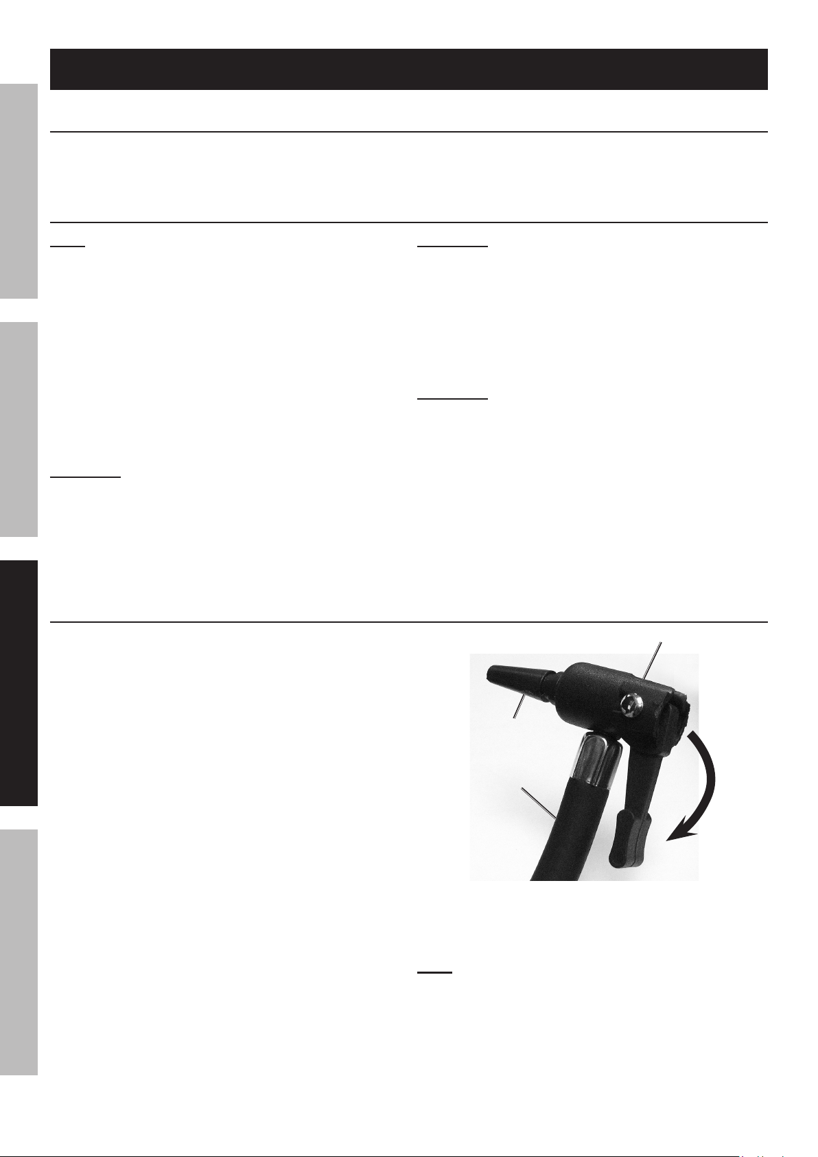
2. Press down the lever. (See Figure E.)
3. Push the Air Compressor Switch
to the “I” (ON) position.
Note: Monitor the Air Pressure Gauge on the
front of the unit to avoid over-inflation.
4. When the proper inflation level has
been reached, push the Air Compressor
Switch to the “O” (OFF) position.
5. Lift the lever and remove the hose.
Page 8 For technical questions, please call 1-800-444-3353. Item 60666
Adapter
installed
Air Hose
Lever
pressed
down
Figure E
Page 9
Using Hose Adapters
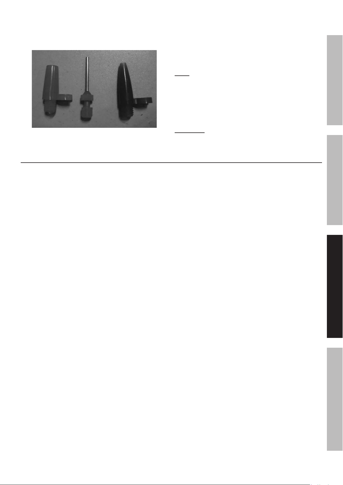
1. Three adapters are included with the Power Pack that
can be attached to the Tire Inflator. (See Figure F.)
2. Attach the proper adapter to the Tire
Inflator for the object to be inflated.
3. Insert the adapter into the object’s
receptacle and press down the lever.
4. Push the Compressor Switch to the “I” (ON) position.
Note: Monitor the Air Pressure Gauge on the
front of the unit to avoid over-inflation.
Figure F
Running/Charging DC Appliances
1. Press the Battery Test Button to verify that the
Power Pack is fully charged. Recharge as needed,
following the instructions in the Setup section under
“Charging the Power Pack” on page 6.
2. Make sure the total wattage of the appliance
or appliances is within the range of the
Power Pack. See Setup section under “DC
Appliance Compatibility” on page 6.
5. When the proper inflation level has
been reached, push the Compressor
Switch to the “O” (OFF) position.
6. Lift the lever and remove the hose.
WARNING! Do not overinflate any object.
3. Make sure that the Clamp Power
and appliance are off.
4. Plug the appliance into the 12VDC Outlet.
5. Turn on the appliance.
6. When finished using, turn off and
unplug the appliance.
SAFETYOPERATIONMAINTENANCE SETUP
Page 9For technical questions, please call 1-800-444-3353.Item 60666
Page 10
Maintenance and Servicing
Procedures not specifically explained in this manual must
be performed only by a qualified technician.
SAFETY OPERATION MAINTENANCESETUP
TO PREVENT SERIOUS INJURY: Unplug the Power Pack, turn the Clamp Power Switch off and allow
Power Pack to cool completely before performing any inspection, maintenance, or cleaning procedures.
1. BEFORE EACH USE, inspect the general
condition of the Power Pack. Check for:
• loose hardware,
• cracked or broken parts,
• damaged electrical wiring or cable insulation, and
• any other condition that may
affect its safe operation.
2. Keep unit clean and clamps free
of dirt, debris, or grease.
3. For longer working life, protect Power
Pack from sunlight and moisture.
4. AFTER USE, wipe external surfaces of
the Power Pack with clean cloth.
5. CONTAINS SEALED LEAD BATTERY.
BATTERY MUST BE RECYCLED.
Battery Replacement and Disposal
LEAD BATTERY MUST BE RECYCLED.
WARNING! To prevent damage or injury, replacement battery must be identical to original.
Replace the Battery when voltage drops
below 9V after recharging.
1. Remove all screws from the back of
the case and lift off the panel.
2. Lift out the Battery without damaging the circuit board.
Note: Notice how the red and black cables connect
to the old battery and make sure to keep them in
place, connecting them to the new battery.
3. Detach the recharging wires and Battery
Cables from the battery terminals.
4. Position the replacement battery with the label
facing out, and make sure the red (+) recharging
wire and Battery Cable is attached to the
positive (+) battery terminal. Connect both of
the recharging wires and Battery Cables.
5. Carefully slide the battery into the compartment
without damaging the circuit board.
6. Replace the back panel and the screws.
Call 1-800-822-8837 for battery recycling.
Light Bulb Replacement
1. Gently squeeze the Light Lens/Bezel
Assembly on the sides and remove it.
Page 10 For technical questions, please call 1-800-444-3353. Item 60666
2. Unscrew the Bulb and replace it.
3. Push the Light Lens/Bezel Assembly back into place.
Page 11
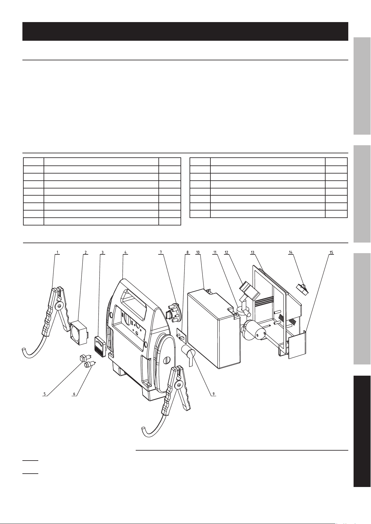
Parts List and Diagram
PLEASE READ THE FOLLOWING CAREFULLY
THE MANUFACTURER AND/OR DISTRIBUTOR HAS PROVIDED THE PARTS LIST AND ASSEMBLY DIAGRAM
IN THIS MANUAL AS A REFERENCE TOOL ONLY. NEITHER THE MANUFACTURER OR DISTRIBUTOR
MAKES ANY REPRESENTATION OR WARRANTY OF ANY KIND TO THE BUYER THAT HE OR SHE IS
QUALIFIED TO MAKE ANY REPAIRS TO THE PRODUCT, OR THAT HE OR SHE IS QUALIFIED TO REPLACE
ANY PARTS OF THE PRODUCT. IN FACT, THE MANUFACTURER AND/OR DISTRIBUTOR EXPRESSLY
STATES THAT ALL REPAIRS AND PARTS REPLACEMENTS SHOULD BE UNDERTAKEN BY CERTIFIED AND
LICENSED TECHNICIANS, AND NOT BY THE BUYER. THE BUYER ASSUMES ALL RISK AND LIABILITY
ARISING OUT OF HIS OR HER REPAIRS TO THE ORIGINAL PRODUCT OR REPLACEMENT PARTS
THERETO, OR ARISING OUT OF HIS OR HER INSTALLATION OF REPLACEMENT PARTS THERETO.
Parts List
SAFETYOPERATIONMAINTENANCE SETUP
Part Description Qty
1 Battery Cable 1
2 Work Light 1
3 Voltmeter 1
4 Front Case 1
5 Work Light Switch 1
6 Battery Test Button 1
7 Clamp Power Swtich 1
8 Circuit Board 1
Assembly Diagram
Part Description Qty
9 12VDC Outlet 1
10 Battery 2
11 Air Compressor 2
12 Air Pressure Gauge 1
13 Back Case 1
14 Air Compressor Switch 1
15 Air Compressor Cover 1
Record Product’s Serial Number Here:
Note: If product has no serial number, record month and year of purchase instead.
Note: Some parts are listed and shown for illustration purposes only, and are not available individually
as replacement parts. Internal parts are not user-serviceable and are not available.
Page 11For technical questions, please call 1-800-444-3353.Item 60666
Page 12

Limited 90 Day Warranty
Harbor Freight Tools Co. makes every effort to assure that its products meet high quality and durability standards,
and warrants to the original purchaser that this product is free from defects in materials and workmanship for the
period of 90 days from the date of purchase. This warranty does not apply to damage due directly or indirectly,
to misuse, abuse, negligence or accidents, repairs or alterations outside our facilities, criminal activity, improper
installation, normal wear and tear, or to lack of maintenance. We shall in no event be liable for death, injuries
to persons or property, or for incidental, contingent, special or consequential damages arising from the use of
our product. Some states do not allow the exclusion or limitation of incidental or consequential damages, so the
above limitation of exclusion may not apply to you. THIS WARRANTY IS EXPRESSLY IN LIEU OF ALL OTHER
WARRANTIES, EXPRESS OR IMPLIED, INCLUDING THE WARRANTIES OF MERCHANTABILITY AND FITNESS.
To take advantage of this warranty, the product or part must be returned to us with transportation charges
prepaid. Proof of purchase date and an explanation of the complaint must accompany the merchandise.
If our inspection verifies the defect, we will either repair or replace the product at our election or we may
elect to refund the purchase price if we cannot readily and quickly provide you with a replacement. We will
return repaired products at our expense, but if we determine there is no defect, or that the defect resulted
from causes not within the scope of our warranty, then you must bear the cost of returning the product.
This warranty gives you specific legal rights and you may also have other rights which vary from state to state.
3491 Mission Oaks Blvd. • PO Box 6009 • Camarillo, CA 93011 • (800) 444-3353
 Loading...