

Page 1

6” DIGITAL CALIPER
Model
47257
OPERATING INSTRUCTIONS
Visit our website at: http://www.harborfreight.com
Read this material before using this product.
Failure to do so can result in serious injury.
SAVE THIS MANUAL.
Copyright© 2009 by Harbor Freight Tools®. All rights reserved. No portion of this manual
or any artwork contained herein may be reproduced in any shape or form without the
express written consent of Harbor Freight Tools. Diagrams within this manual may not
be drawn proportionally. Due to continuing improvements, actual product may differ
slightly from the product described herein. Tools required for assembly and service may
not be included.
For technical questions or replacement parts, please call 1-800-444-3353.
Page 2

Page 2SKU 47257 For technical questions, please call 1-800-444-3353.
SAVE THIS MANUAL
Keep this manual for the safety
warnings and precautions, assembly,
operating, inspection, maintenance and
cleaning procedures. Write the product’s
serial number in the back of the manual
near the assembly diagram (or month and
year of purchase if product has no number). Keep this manual and the receipt in a
safe and dry place for future reference.
IMPORTANT SAFETY
INFORMATION
In this manual, on the labeling,
and all other information
provided with this product:
This is the safety alert
symbol. It is used to alert
you to potential personal
injury hazards. Obey all
safety messages that
follow this symbol to avoid
possible injury or death.
DANGER indicates
a hazardous
situation which, if not
avoided, will result in death or
serious injury.
WARNING indicates
a hazardous
situation which, if not
avoided, could result in death
or serious injury.
CAUTION, used
with the safety alert
symbol, indicates a
hazardous situation which, if
not avoided, could result in
minor or moderate injury.
NOTICE is used to
address practices
not related to personal injury.
CAUTION, without
the safety alert
symbol, is used to address
practices not related to
personal injury.
GENERAL AND SPECIFIC
SAFETY RULES
WARNING! Read all
instructions.
Failure to follow all instructions
listed below may result in
serious injury.
SAVE THESE INSTRUCTIONS
Work area safety1.
Keep out of the reach of children.a.
Wear ANSI-approved safety b.
goggles during use.
Read this manual before use.c.
Keep work area clean and well d.
lit. Cluttered or dark areas invite
accidents.
When not in use, store in a dry e.
location.
This Digital Caliper was designed f.
for specic tasks. Do not modify
this tool and do not use it for purposes for which it was not intended.
Do not operate while you are g.
tired, or under the inuence of
alcohol or drugs. A moment of
inattention may result in damage to
your project and/or personal injury.
Maintain labels and nameplates h.
on the tool. These carry important
safety information. If unreadable
or missing, contact Harbor Freight
Tools for a replacement.
Page 3

Page 3SKU 47257 For technical questions, please call 1-800-444-3353.
The warnings, precautions, and i.
instructions discussed in this
instruction manual cannot cover all
possible conditions and situations
that may occur. It must be understood by the operator that common
sense and caution are factors which
cannot be built into this product, but
must be supplied by the operator.
SAVE THESE
INSTRUCTIONS.
SPECIFICATIONS
Display Scales Inches & Millimeters
Display Digits LCD (Liquid Crystal Display)
Range 0” - 6”, Or 0mm - 200mm
Accuracy
Inches: ±0.001"
Metric: ±0.03mm
Display
Inches: 0.0005"
Metric: 0.01mm
Measuring
Positions
4-Way Measuring:
Outside, Inside, Depth, Step
Power Supply
One 1.5V DC SR44 Button
Cell Battery (Included)
Shut-Off
Off Button,
4-1/2 Minute (Automatic)
UNPACKING
When unpacking, check to make
sure that the item is intact and undamaged. If any parts are missing or broken,
please call Harbor Freight Tools at the
number shown on the cover of this manual
as soon as possible.
List of Contents
Part(s) Description Qty
1 6” Digital Calliper 1
1 Foam Lined Molded Case 1
1 Cell Battery (One inserted into
caliper and one in case)
2
OPERATING INSTRUCTIONS
Read the ENTIRE
IMPORTANT SAFETY
INFORMATION section at
the beginning of this manual
including all text under
subheadings therein before set
up or use of this product.
Note: Do not bump or shock the Digital
Caliper. Rough treatment may damage the highly sensitive mechanism.
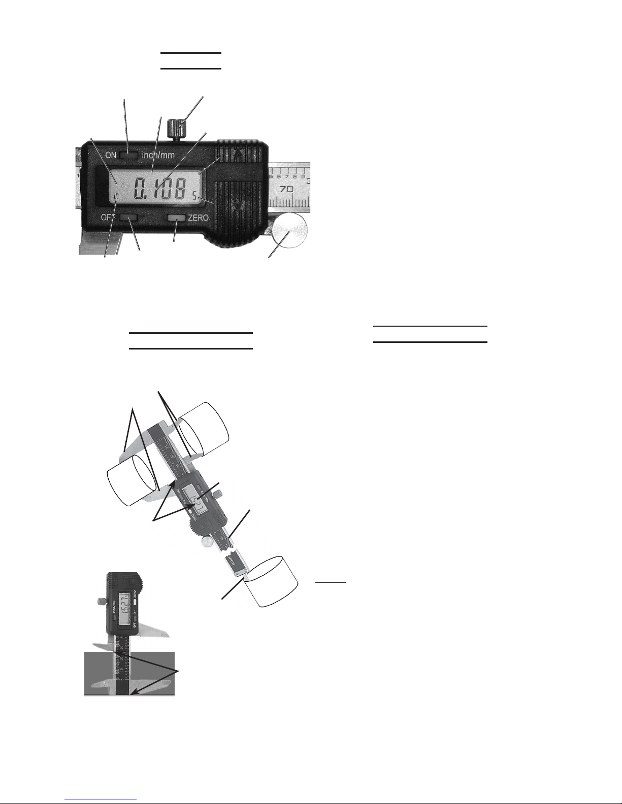
Components and Controls
Figure 1
LCD
Screen
Depth
Measuring
Blade
Locking
Screw
Sliding
Ruler
Inside
Measurement
Jaws
Outside
Measurement
Jaws
Thumb
Wheel
Page 4
Page 4SKU 47257 For technical questions, please call 1-800-444-3353.
Controls
Off Button
Figure 2
LCD
Screen
Locking
Screw
On Button /
Metric to Inches
Button
.0005
Increment
for Inches
Inches
Indicator
Metric
Indicator
Measurement
Readout
Zero Button
Thumb Wheel
mm
-
Negative
Reading
Indicator
Measuring Points
Figure 3
LCD
Readout
Depth
Measuring
Blade
Sliding Ruler
Read
Measurement
on the LCD or
Sliding Ruler
Step Measurement -
From bottom of Sliding
Ruler to edge of the
Inside Measurement Jaw
Inside
Measurement
Jaws
Outside
Measurement
Jaws
This tool has four measuring points:
Outside Measurement Jaws, which •
are placed on the outside of an
object to measure the outer dimensions.
Inside Measurement Jaws, which •
are placed inside a hollow object to
measure the inside dimensions.
Depth Measuring Blade, which is •
lowered inside a hollow object to
measure it’s depth from the tip of
the Blade to the end of the Sliding
Ruler.
Step Measurement, which is mea-•
sured from the bottom of the Sliding
Ruler to the ledge created on the
backside of the tool by the second
Inside Measurement Jaw.
Basic Operation
Press the On Button to turn the LCD 1.
on.
Turn the Locking Screw counterclock-2.
wise to loosen the Sliding Ruler.
Slide the Jaws open and wipe them 3.
off so they are free of any debris.
Push the Jaws together, then press 4.
the Zero Button to set the measuring
mechanism to zero.
If needed, press the Metric/Inches 5.
Button to change the readout between
measuring inches or millimeters.
Note: The same button is used to turn on
the unit and to change the readout
between metric and inches.
Slide the Sliding Ruler toward the 6.
jaws, separating the jaws or lengthen-
ingtheDepthBladeenoughtotthe
object you wish to measure.
Adjust the Jaws or Depth Blade with 7.
the Thumb Wheel, as needed, until
there is gentle contact with the object.
Page 5
Page 5SKU 47257 For technical questions, please call 1-800-444-3353.
Read the measurement in the LCD 8.
Screen or on the Sliding Ruler.
Note: Make sure the tool is perpendicular
to the object so you will get an accurate reading.
Note: The LCD readout displays met-
ric measurements to the nearest
0.01mm, and to the nearest 0.0005”
formeasurementsininches.Thenal
digit for the inches measurement is
in the lower right corner of the LCD
Screen and displays only when the
measurement is 0.0005 greater than
the 0.001 increment.
Whennishedmeasuring,closethe9.
jaws, press the “OFF” Button to turn
the Digital Caliper off, wipe off the unit
with a soft cloth and replace in case.
Store in a safe, dry place out of reach
of children.
Single Measurements
Note: To ensure an accurate reading:
Make sure the Jaw faces are clean.a.
Set the Measurement Readout to b.
zero.
Make sure you position the Caliper c.
perpendicular to the object when
measuring.
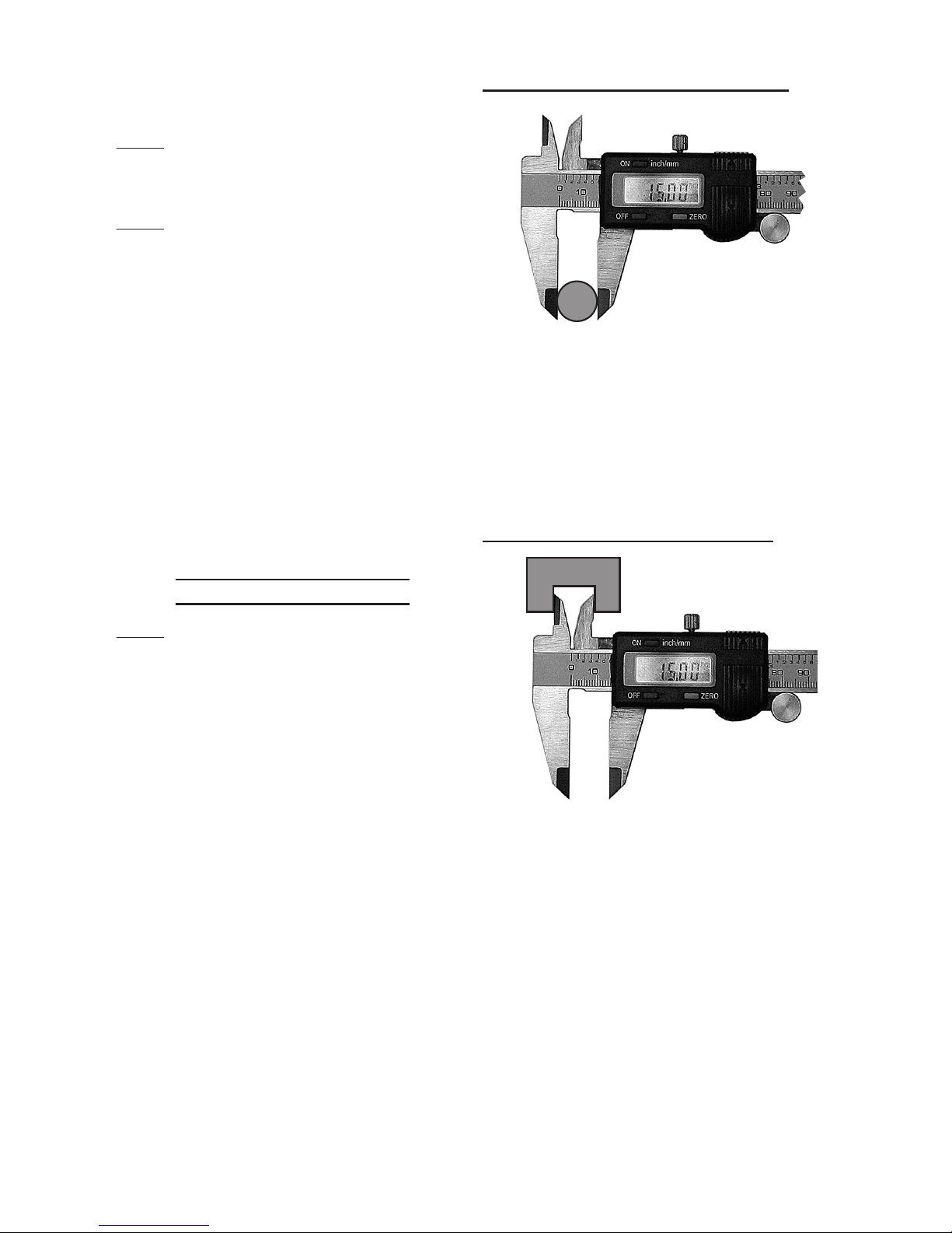
To make an Outside Measurement:
Figure 4
Slide the jaws open and place the
item to measure between the Outside
Measurement Jaws. Slide the jaws
together until they gently contact the
item. Read the measurement on the
ruler or the LCD Screen.
To make an Inside Measurement:
Figure 5
Slide the jaws closed and place the
Inside Measurement Jaws inside the
item to measure. Slide the jaws open
until they gently contact the item.
Read the measurement on the ruler
or the LCD Screen.
Page 6
Page 6SKU 47257 For technical questions, please call 1-800-444-3353.
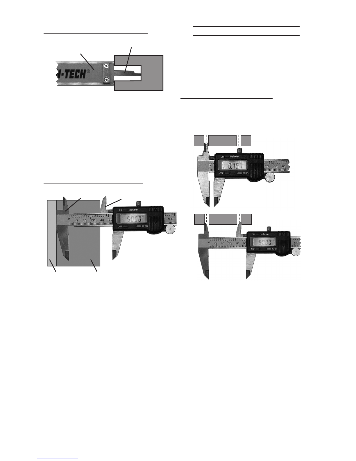
To make a Depth Measurement:
Figure 6
Sliding Ruler
Depth Measuring Blade
Rest the end of the Sliding Ruler on
the edge of the hole to measure. Slide
the jaws open until the Depth Measuring Blade gently contacts the bottom
of the hole. Read the measurement
on the ruler or LCD Screen.
To make a Step Measurement:
Figure 7
Stationary Jaw
Moving Jaw
Upper stepLower step
Slide the jaws apart and rest the head
of the moving jaw on the lower step.
Continue sliding the jaws apart until
you can rest the head of the stationary jaw on the top of the upper step to
measure. Read the measurement on
the ruler or LCD Screen.
Compound Measurements
To take a compound measurement,
you measure one part of the object,
then zero out the Caliper, then take
a different measurement. This allows
you to make complex measurements.
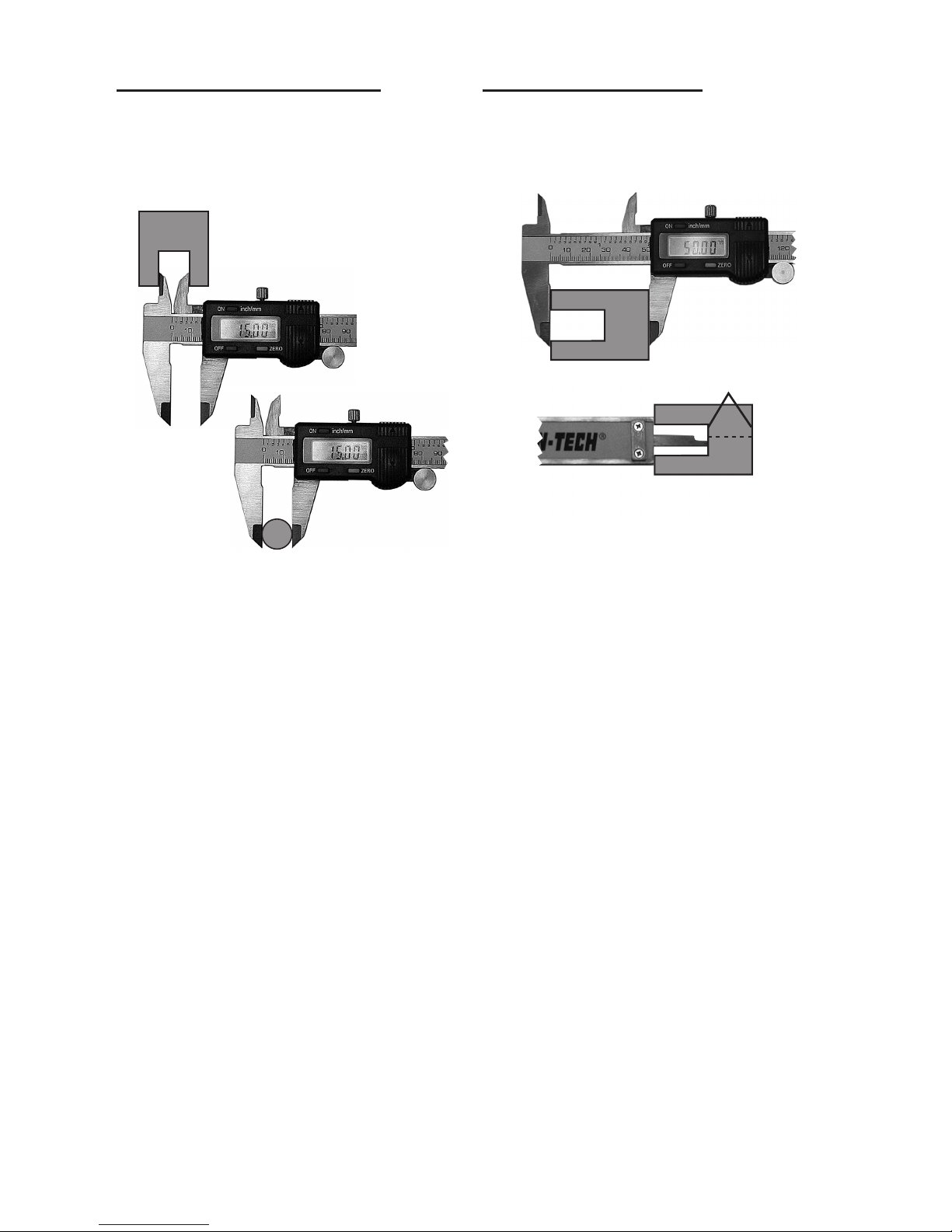
To nd the Center Distance:
This two step procedure measures
the distance between the center of
two identical holes.
Figure 8
Step 1
Step 2
1. Using the Inside Measurement Jaws,
measure the inside diameter of one of
the holes. Press the Zero Button while
the Caliper is opened to the hole
measurement.
Remove the jaws from the hole and 2.
slide the Caliper so that the Inside
Measurement Jaws have gentle
contact with the far sides of the two
holes. The measurement displayed
is the distance between the center of
the two holes.
Page 7
Page 7SKU 47257 For technical questions, please call 1-800-444-3353.
To Compare a Shaft to a Hole:
This two step procedure is useful
in tooling, when you need to see if
a dowel, pin or other cylinder is the
same size as a hole.
Figure 9
Step 1
Step 2
1. Using the Inside Measurement Jaws,
measure the inside diameter of hole.
Press the Zero Button while the Caliper is opened to the hole measurement. Remove the jaws from the hole.
Using the Outside Measurement 2.
Jaws, measure the dowel, pin or cylinder. The three possible conditions are:
If the measurement is zero, then c.
the object is the same size as the
hole.
If the measurement is negative (the d.
minus sign is displayed) then the
object is smaller than the hole by
the amount shown.
If the measurement is positive, then e.
the object is larger than the hole by
the amount shown.
To Determine Thickness:
Use this two step procedure to determine the material remaining when
drilling a hole.
Step 1
Step 2
Figure 10
Measures this
distance
1. Using the Outside Measurement
Jaws, measure the total length of the
object. Press the Zero Button while
the Caliper is opened to the measurement. Remove the tool from the
object.
Using the Depth Measurement Blade, 2.
measure the inside of the hole. The
reading will show a negative number,
which is the remaining thickness of
the material.
Page 8
Page 8SKU 47257 For technical questions, please call 1-800-444-3353.
Replacing The Battery
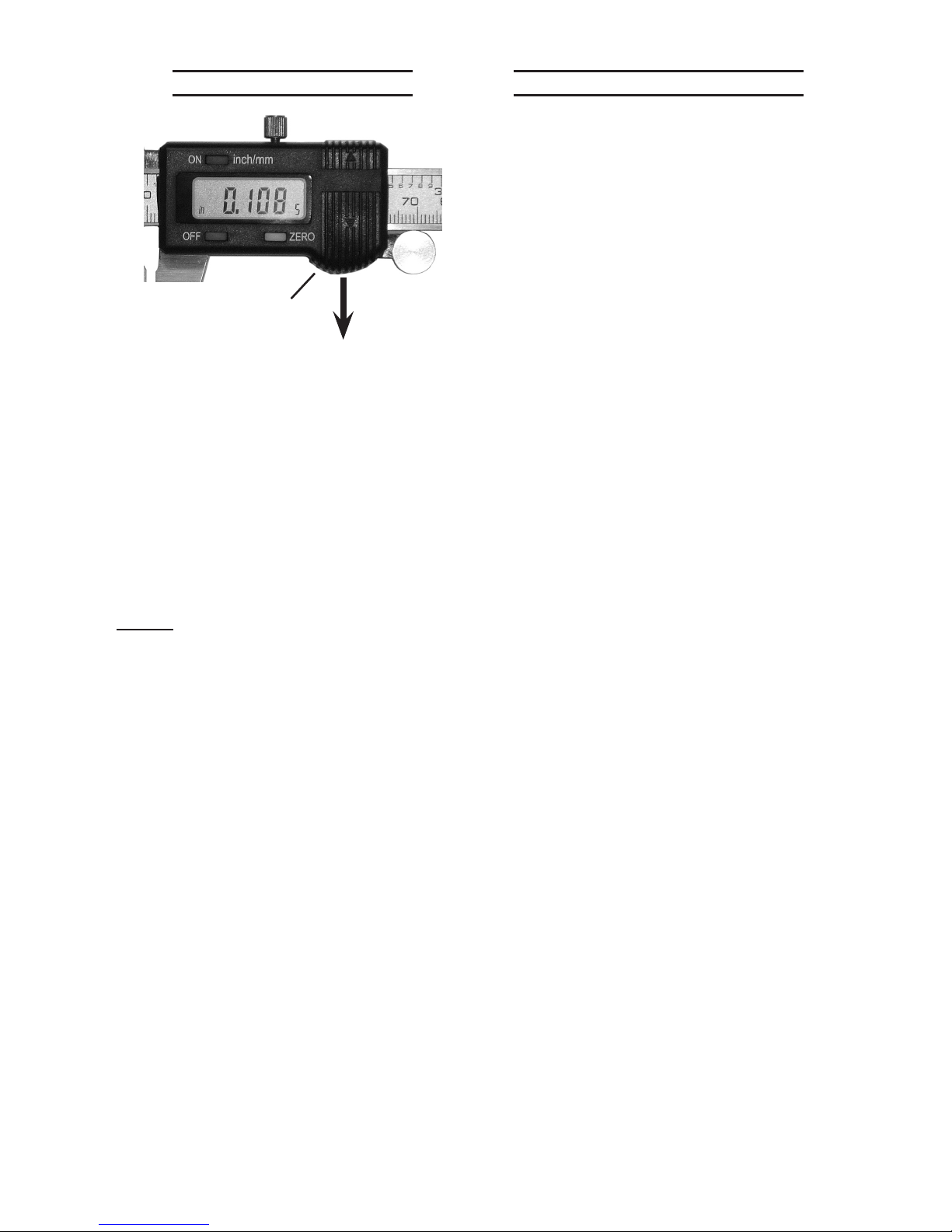
Figure 3
Battery Cover
1. Remove the Battery Cover by sliding
the cover in the direction shown in
Figure 3 above, then tilt the cover up
and off of the unit.
Remove the existing Battery and 2.
replace with an identical Battery as
listedinthe“Specications”charton
page 3 of this manual.
Replace the Battery Cover.3.
NOTE: Dispose of the used Battery in ac-
cordance with all local ordinances.
Cleaning And Maintenance
BEFORE EACH USE, inspect the 1.
general condition of the tool. Check
for any condition that may affect its
safe operation.
After use, wipe with soft, clean cloth 2.
and store inside, away from extreme
hot, or cold and where children do not
have access.
The LCD display and Jaw faces 3.
should be wiped periodically with a
clean, dry, lint-free cloth.
Lubricate the body of the Caliper with 4.
a few drops of clock oil.
Keep Battery Compartment clean, dry 5.
and free of corrosion.
Keep this Caliper dry at all times to 6.
prevent destroying the electronics.
Page 9

Page 9SKU 47257 For technical questions, please call 1-800-444-3353.
PLEASE READ THE FOLLOWING CAREFULLY
NEITHER THE MANUFACTURER OR DISTRIBUTOR MAKES ANY REPRESENTATION OR
WARRANTY OF ANY KIND TO THE BUYER THAT HE OR SHE IS QUALIFIED TO MAKE ANY
REPAIRS TO THE PRODUCT, OR THAT HE OR SHE IS QUALIFIED TO REPLACE ANY PARTS
OF THE PRODUCT. IN FACT, THE MANUFACTURER AND/OR DISTRIBUTOR EXPRESSLY
STATES THAT ALL REPAIRS AND PARTS REPLACEMENTS SHOULD BE UNDERTAKEN BY
CERTIFIED AND LICENSED TECHNICIANS, AND NOT BY THE BUYER. THE BUYER ASSUMES ALL RISK AND LIABILITY ARISING OUT OF HIS OR HER REPAIRS TO THE ORIGINAL PRODUCT OR REPLACEMENT PARTS THERETO, OR ARISING OUT OF HIS OR HER
INSTALLATION OF REPLACEMENT PARTS THERETO.
LIMITED 90 DAY WARRANTY
Harbor Freight Tools Co. makes every effort to assure that its products meet
high quality and durability standards, and warrants to the original purchaser that this
product is free from defects in materials and workmanship for the period of 90 days
from the date of purchase. This warranty does not apply to damage due directly or
indirectly, to misuse, abuse, negligence or accidents, repairs or alterations outside
our facilities, criminal activity, improper installation, normal wear and tear, or to lack of
maintenance. We shall in no event be liable for death, injuries to persons or property,
or for incidental, contingent, special or consequential damages arising from the use of
our product. Some states do not allow the exclusion or limitation of incidental or consequential damages, so the above limitation of exclusion may not apply to you. THIS
WARRANTY IS EXPRESSLY IN LIEU OF ALL OTHER WARRANTIES, EXPRESS OR
IMPLIED, INCLUDING THE WARRANTIES OF MERCHANTABILITY AND FITNESS.
To take advantage of this warranty, the product or part must be returned to us
with transportation charges prepaid. Proof of purchase date and an explanation of the
complaintmustaccompanythemerchandise.Ifourinspectionveriesthedefect,we
will either repair or replace the product at our election or we may elect to refund the
purchase price if we cannot readily and quickly provide you with a replacement. We will
return repaired products at our expense, but if we determine there is no defect, or that
the defect resulted from causes not within the scope of our warranty, then you must
bear the cost of returning the product.
Thiswarrantygivesyouspeciclegalrightsandyoumayalsohaveotherrights
which vary from state to state.
3491 Mission Oaks Blvd. • PO Box 6009 • Camarillo, CA 93011 • (800) 444-3353
Record Product’s Serial Number Here:
Note: If product has no serial number, record month and year of purchase instead.
Note: Some parts are listed and shown for illustration purposes only, and are not
available individually as replacement parts.
 Loading...