

Page 1
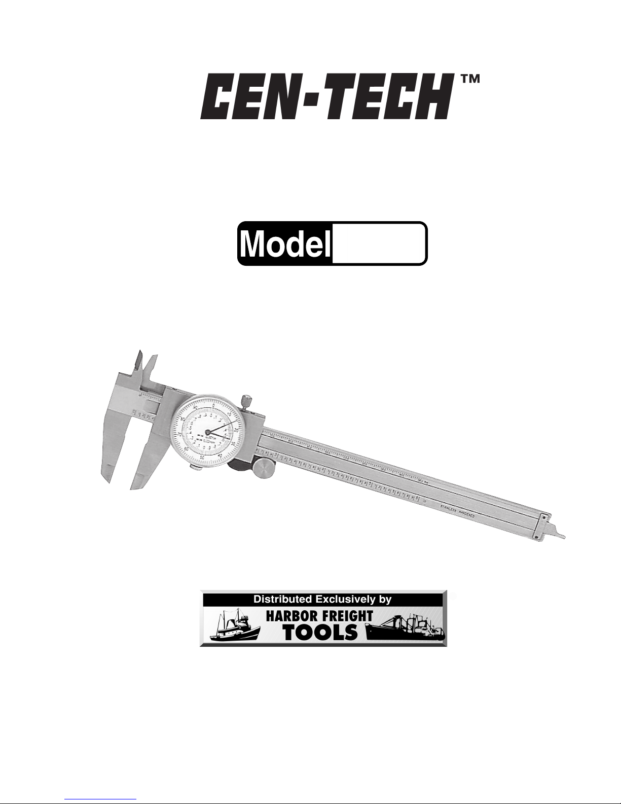
6” DIAL CALIPER
®
40926
OPERATING INFORMATION
3491 Mission Oaks Blvd., Camarillo, CA 93011
Visit our W eb site at http://www.harborfreight.com
Copyright© 2001 by Harbor F reight T ools®. All rights reserved. No portion of this manual
or any artwork contained herein may be reproduced in any shape or form without the
e xpress written consent of Harbor F reight Tools.
For technical questions please call 1-800-444-3353
REV 04/06
Page 2

SPECIFICATIONS
ITEM DESCRIPTION
Construction
Overall Dimensions
Scale Inches
Scale Metric
Dial Markings
Accuracy
Stainless Steel
6” L x 3” W
.10”/line
1mm/line
Red Numerals = Inches / Black Numerals = Metric
Within .0005”
SAVE THIS MANUAL
You will need the manual for the safety warnings and precautions, assembly
instructions, operating and maintenance procedures, parts list and diagram. Keep
your inv oice with this manual. Write the invoice number on the inside of the front
cover. Keep the manual and invoice in a safe and dry place for future reference.
GENERAL SAFETY WARNINGS AND PRECAUTIONS
1. KEEP PRODUCT USAGE AREA CLEAN. Cluttered areas invite injuries.
2. KEEP CHILDREN AWAY FROM PRODUCT USAGE AREA. Do not allow
children to handle this product.
3. USE EYE PROTECTION. Wear ANSI-approved safety impact eye glasses.
ANSI-approved safety impact eye glasses are available from Harbor Freight
Tools.
4. CHECK FOR DAMAGED PARTS. Before using this product, carefully check
that it will operate properly and perform its intended function. Check for damaged parts and any other conditions that may affect its operation. Replace or
repair damaged or worn parts immediately.
5. REPLACEMENT PARTS AND ACCESSORIES. When ser vicing, use only
identical replacement parts. Only use accessories intended for use with this
product.
6. MAINTENANCE: Service and maintenance should be performed regularly by a
qualified technician.
7. USE THE RIGHT PRODUCT FOR THE RIGHT JOB. There are certain appli-
cations for which this product was designed. Do not use a smaller tool to do the
work required by a larger industrial size tool. Do not use this product for a
purpose for which it was not intended.
Page 2SKU 40926 For technical questions, please call 1-800-444-3353.
Page 3
8. KEEP THE CALIPER FREE FROM WATER, OIL, SOLVENTS, ETCETERA.
9. DO NOT APPLY FORCE OR A SHOCK TO THE CALIPER.
10. DO NOT DISASSEMBLE THE CALIPER.
UNPACKING
When unpacking, check to make sure all parts shown on the Parts List (page 6)
are included. If any parts are missing or broken, please call Harbor Freight Tools at the
number shown on the cover of this manual as soon as possible.
OPERATING INSTRUCTIONS
NOTE: All parts listed below refer to the parts shown on page 6 of this manual.
To Prepare
The Caliper For Use:
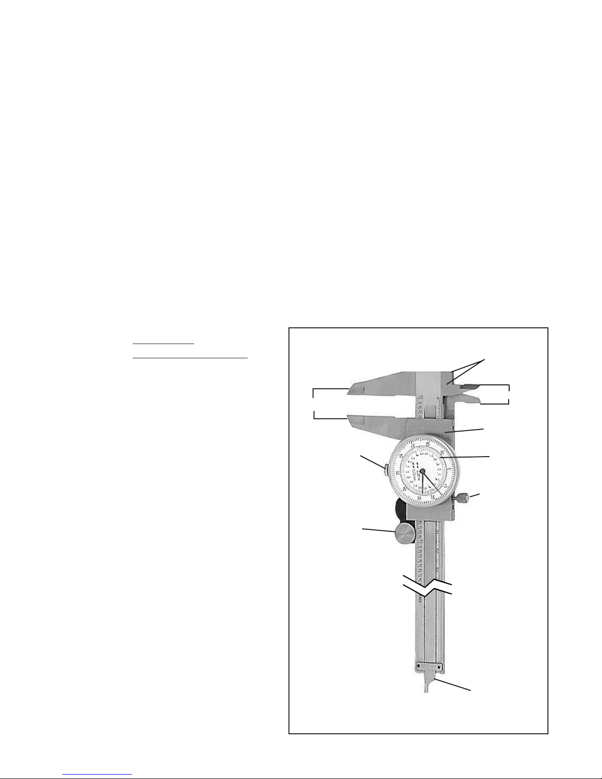
1. Make sure the upper and
lower Outside Diameter Jaw
surfaces (2) are clean.
(See Figure A.)
2. Loosen the Slide Scale
Lock (6) by turning it counterclockwise.
O.D. Jaws
Adjustment
Slide
Measurement Point
Dial
Lock
Step Measuring
Surface
I.D. Jaws
Dial
Adjustment
Dial Needle
3. Close the Outside Diameter
Jaws (2) by using the
Thumbroll (1).
4. At this point, the Slide Scale
Measurement Point (7)
should read “0”.
5. Loosen the Dial Adjustment
Lock (3) by turning it counterclockwise.
6. Set the Dial (5) by turning
the Dial Adjustment (4)
either clockwise or counterclockwise until the Dial
Needle points to “0”.
Slide
Scale Lock
Thumbroll
Depth
Measuring
Surface
FIGURE A
Page 3SKU 40926 For technical questions, please call 1-800-444-3353.
Page 4
7. Lock the Dial (5) to its “0” setting by tightening the Dial Adjustment Lock (3)
clockwise.
8.
The Caliper is now ready for use.
To Read The Scale And Dial:
1. The Slide Scale Measurement Point (7) features both Inches and Metric readings. (.10” per line, and 1mm per line)
2 . The Dial (5) features both Inches and Metric readings. (.001” per line, and
.254mm per line)
3. First, read the Slide Scale Measurement Point (in inches and tenths of inches),
i.e., 0.5”. Then, read the Dial Needle on the Dial (in thousandths of an inch), i.e.,
.081”.
4 . Combine the two measurements for the final reading, 0.581” or 14.76 mm
(NOTE: 0.581” x 25.4 mm = 14.76 mm)
To Use The Caliper:
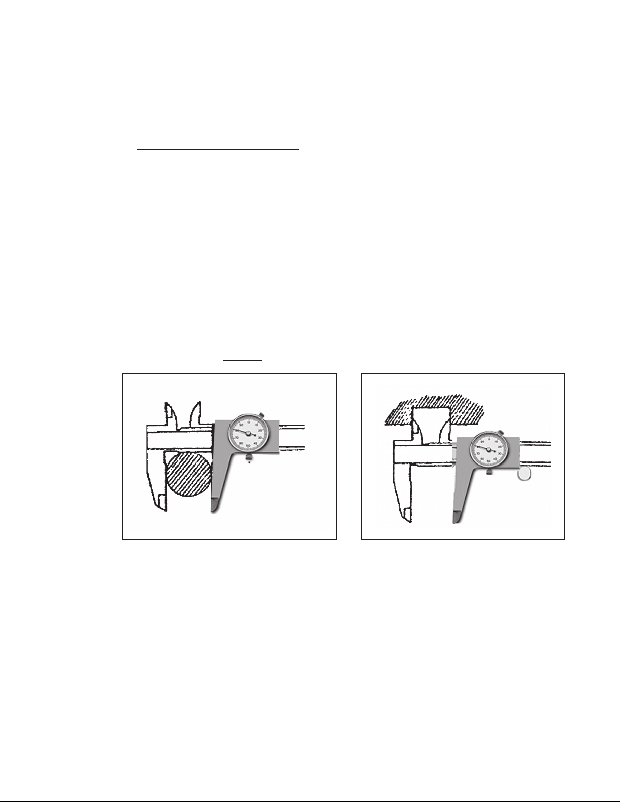
1. To measure the
outside
diameter of an object see Figure B.
FIGURE B FIGURE C
2. To measure the
inside
diameter of an object see Figure C.
Page 4SKU 40926 For technical questions, please call 1-800-444-3353.
Page 5
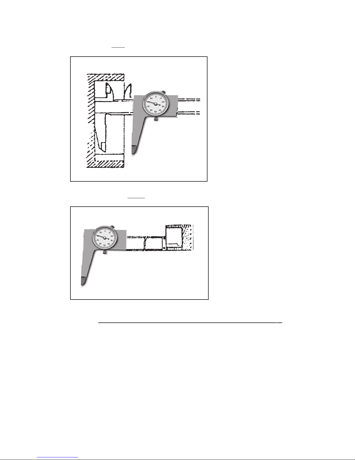
3. To make a
step
measurement of an object see Figure D.
FIGURE D
4. To measure the
depth
of an object see Figure E.
FIGURE E
PLEASE READ THE FOLLOWING CAREFULLY
THE MANUF ACTURER AND/OR DISTRIBUTOR HAS PR OVIDED THE P ARTS DIAGRAM IN THIS MANU AL
AS A REFERENCE TOOL ONLY. NEITHER THE MANUFACTURER NOR DISTRIBUTOR MAKES ANY
REPRESENT ATION OR WARRANTY OF ANY KIND TO THE BUYER THAT HE OR SHE IS QUALIFIED T O
MAKE ANY REPAIRS TO THE PRODUCT OR THAT HE OR SHE IS QUALIFIED TO REPLACE ANY
P AR TS OF THE PRODUCT . IN F A CT , THE MANUF ACTURER AND/OR DISTRIBUT OR EXPRESSL Y ST ATES
THAT ALL REPAIRS AND PARTS REPLACEMENTS SHOULD BE UNDERTAKEN BY CERTIFIED AND
LICENSED TECHNICIANS AND NOT BY THE BUYER. THE BUYER ASSUMES ALL RISK AND LIABILITY ARISING OUT OF HIS OR HER REP AIRS T O THE ORIGINAL PRODUCT OR REPLA CEMENT P ARTS
THERETO , OR ARISING OUT OF HIS OR HER INSTALLA TION OF REPLACEMENT PARTS THERETO .
Page 5SKU 40926 For technical questions, please call 1-800-444-3353.
Page 6
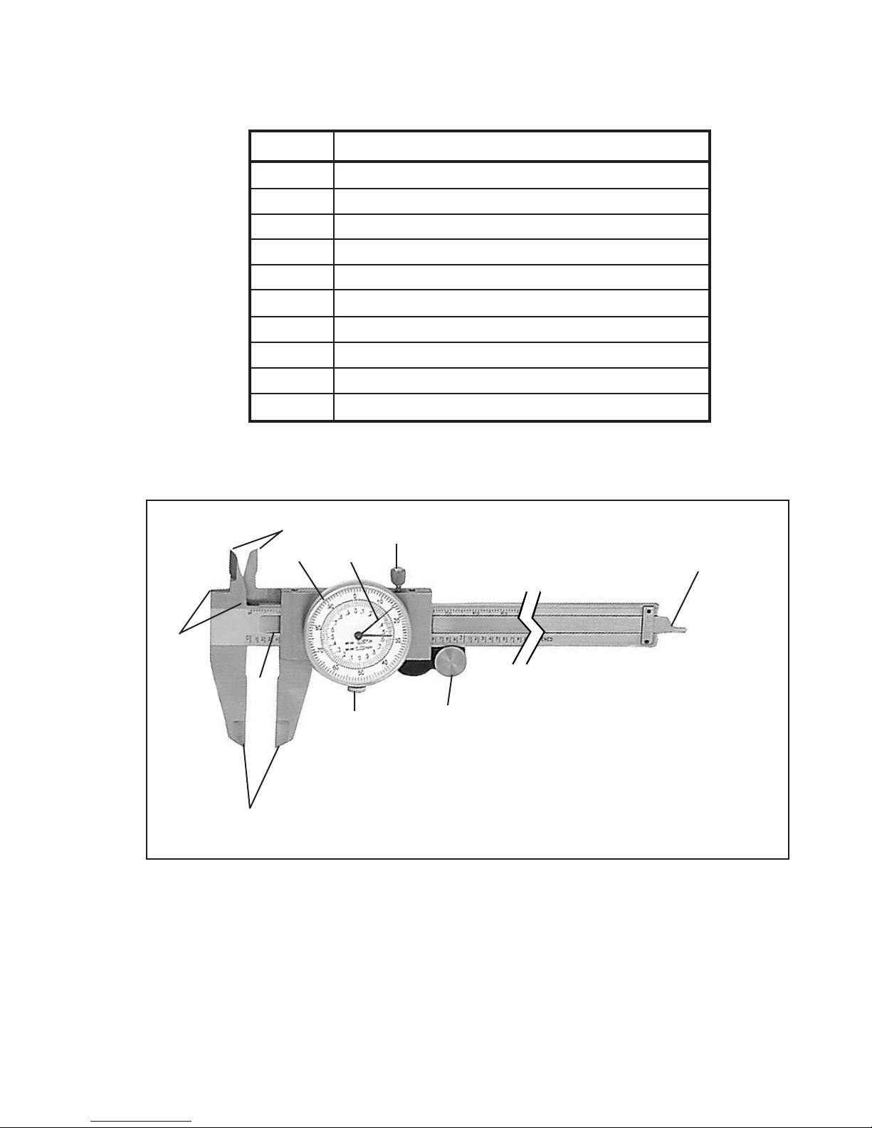
PARTS LIST
PART # DESCRIPTION
1
2
3
4
5
6
7
8
9
10
Thumbroll
Outside Diameter Jaws
Dial Adjustment Lock
Dial Adjustment
Dial (Red = SAE / Black = Metric)
Slide Scale Lock
Slide Scale Measurement Point (SAE/Metric)
Inside Diameter Jaws
Step Measuring Surfaces
Depth Measuring Surface
PARTS ASSEMBLY
8
4
5
6
10
9
7
3
1
2
NO TE: Some parts are listed and shown for illustration
pur poses only, and are not available individually as replacement par ts.
Page 6SKU 40926 For technical questions, please call 1-800-444-3353.
 Loading...