

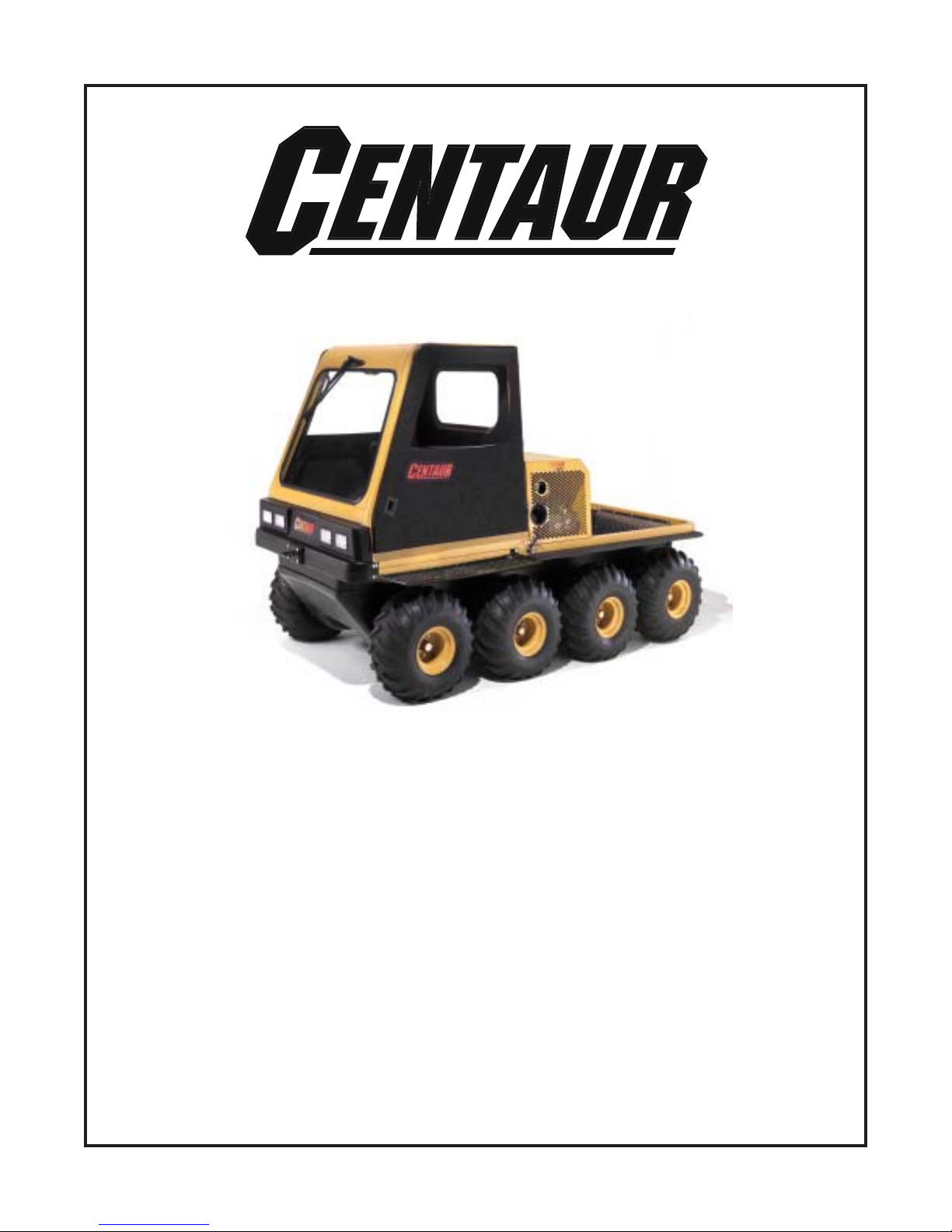
Centaur CENTAUR, Centaur V2003G, Centaur V2003DT, amphibious, off-road utility vehicle Operator's Manual
Page 1
OPERATOR’S
MANUAL
Do not remove this
manual from this vehicle.
T elephone: (519) 662-2840, Fax: (519) 662-2421
MANUAL NO. 671-102 Printed in Canada 2007/07/12
Ontario Drive & Gear Limited
220 Bergey Court
New Hamburg, Ontario N3A 2J5
www.cent aur8x8.ca
Page 2

A MESSAGE FROM THE PEOPLE WHO BUILT YOUR CENTAUR
Thank you for selecting a CENTAUR amphibious, off-road utility vehicle!
Ontario Drive & Gear Limited has been building off road vehicles since 1967. By listening carefully to our
customers and responding to their needs, we have been constantly improving them and will continue to do
so.
Over thirty thousand vehicles have provided reliable service all over the world. From Britain to the Far East,
Alaska to the Antarctic, and from the tropical forests of South America to the deserts of Saudi Arabia. W e are
proud to provide you with a vehicle that represents the ultimate in amphibious, all-terrain transportation.
Your safety and the safety of all CENTAUR users is of the greatest concern to us. You will find numerous
safety statements in this manual. Please read and follow them carefully . Always be safety conscious when
you operate your CENTAUR and remember it is a motorized vehicle.
The CENTAUR is easy to drive and you will soon be tempted to take on new challenges. Please take the
time to develop your driving skills before doing so. Observe the recommendations outlined in this Operator’s Manual and remember; some things are just impossible, even with a CENTAUR.
WELCOME TO THE WORLD WIDE CENT AUR FAMIL Y!
Centaur Service Manual
Ontario Drive & Gear has a service manual which provides the Centaur owner
with step-by-step instructions on how to perform full service procedures on
your vehicle. Everything from removal and replacement of brake pads to rebuilding the transmission. It’s all there. Removal and replacement of engines is
included, however, engine overhaul is not. A separate overhaul manual is available for each engine from your Centaur dealer. Order the service manual on
CD-ROM from your dealer.
Page 3

Read this manual before you operate your CENTAUR. It contains safe operating instructions
and warns the user about potential hazards that can result in personal injury.
W arnings are identified in the text by the following symbol:
W arning text warns the user about potential hazards that can result in personal injury or death.
Cautions are identified in the text by the following symbol:
Caution text contains cautions that can prevent damage to the vehicle.
This manual is based on the latest product information available at the time of printing. Ontario
Drive & Gear Limited reserves the right to make changes at any time and without obligation.
Reproduction of any part of this publication is prohibited without prior written permission.
© Ontario Drive & Gear Limited, 2002
I
Page 4

PREFACE
This manual describes the controls, operation and basic maintenance procedures for all CENT AUR vehicles. Please take the time
to read this manual carefully , for your safety and that of others. By following these instructions, you will ensure extended, trouble
free operation of your vehicle.
For maintenance and adjustment of the engine, refer to the engine manufacturer’s operation and maintenance manual included in your vehicle’s information package.
Before you drive your CENTAUR, make sure you understand how to use all controls, particularly the brakes and steering
system. Learn how to drive your vehicle in an open level area, away from buildings, trees and other obstacles, until you are
completely familiar with its operating characteristics. Drive very slowly until your driving skills improve, and drive with
caution and consideration at all times. The risk of accident or injury is greatest during the first weeks of use. Take special care
during this period. ALWAYS RESPECT OUR ENVIRONMENT.
CAUTION TO THE CENTAUR OWNER/OPERATOR
• Make sure everyone who drives this vehicle receives proper operating instructions and reads this Operator’s Manual.
• No one under the age of 16 should be allowed to operate the CENTAUR. Children under the age of 16 may not have the
skills, abilities or judgement needed to operate the Centaur safely and may be involved in an accident causing severe
injury or death.
• Never allow anyone under the influence of alcohol or any other intoxicating substance to drive or ride in the vehicle.
• Wear an approved safety helmet and eye protection when driving or riding in the vehicle.
• Special operating and safety procedures described in this manual must be observed before and during water operation as
outlined in Section 5.6.
• The use of approved hearing protection is recommended.
• Equip your vehicle with a fire extinguisher and a first aid kit.
• Equip your vehicle with basic tools for emergency repairs.
• Before starting your engine, check for spilled fuel and wipe any up immediately. Any fuel is a potentially explosive
substance that can cause serious personal injury when ignited.
• Keep the floor pans secured in place at all times. Fingers, feet, animal tails or paws can be injured in the drive components
beneath the floor pans. The floor pans also help keep damaging debris out of the drive components.
• Make sure all passengers remain seated while the vehicle is in motion. Advise your passengers to hold onto the vehicle at
all times.
• W ear seatbelts when riding in a vehicle equipped with a ROPS.
• Never overload your vehicle. Trying to steer an overloaded vehicle can damage the steering system. Overloading your
vehicle can lead to costly damage to steering system, transmission, drive chains, axles or bearings. Follow the recommended load capacity for your vehicle listed in Section 1.
• Do not drive the vehicle at high speeds over unfamiliar or rough terrain. Personal injury or vehicle damage may result.
• Certain terrain and steep hills cannot be traversed safely with the Centaur or any other vehicle. Do not attempt to drive
over terrain that is questionable.
• Use common sense at all times when driving your vehicle.
IMPORTANT
Operate this vehicle with safety constantly in mind. Off-road vehicles face unpredictable and often hazardous terrain conditions. It is ultimately the operator’s responsibility to handle the vehicle safely within its limitations and to decide when and
where to travel.
II
Page 5

T ABLE OF CONTENTS
SECTION PAGE
1.0 GENERAL INFORMATION
1.1 AMPHIBIOUS OPERATION ...................................................................................................................... 1
1.2 MAINTENANCE PROCEDURES .............................................................................................................. 1
1.3 WIND CHILL FACTOR............................................................................................................................... 1
1.4 MODEL IDENTIFICATION ....................................................................................................................... 1
1.4.1 Centaur Vehicle Capacity............................................................................................................... 3
1.5 IDENTIFICATION AND LOCATION OF CONTROLS............................................................................ 3
1.6 CE MARKED CENTAURS ......................................................................................................................... 3
1.7 INFORMATION LABELS ........................................................................................................................... 4
2.0 GENERAL OPERATING INFORMATION
2.1 NEW VEHICLE “BREAK-IN” PROCEDURE ........................................................................................... 5
2.2 PRE-OPERATION CHECKS....................................................................................................................... 5
2.3 CARRYING PASSENGERS AND CARGO................................................................................................5
2.4 FUELING THE VEHICLE .......................................................................................................................... 5
Centaur 950 and 954 - Gasoline ..................................................................................................................... 6
Centaur 950DT - Diesel ................................................................................................................................. 6
2.5 VENTED FUEL SYSTEM .............................................................................................................................. 6
3.0 OPERATING INSTRUCTIONS
3.1 STEERING ................................................................................................................................................... 7
3.2 BRAKES....................................................................................................................................................... 7
3.3 PARKING/EMERGENCY BRAKE ............................................................................................................ 7
3.4 THROTTLE CONTROL.............................................................................................................................. 7
3.5 STARTING PROCEDURE ..........................................................................................................................7
3.5.1 Gasoline Powered........................................................................................................................... 7
3.5.2 Diesel Powered ...............................................................................................................................8
3.6 STOPPING THE ENGINE .......................................................................................................................... 8
3.7 SELECTING AND CHANGING TRANSMISSION GEARS .................................................................... 8
3.8 HEADLIGHTS ............................................................................................................................................. 9
4.0 DRIVING PROCEDURES
4.1 DRIVING STRAIGHT AHEAD ................................................................................................................10
4.2 STOPPING THE VEHICLE ...................................................................................................................... 10
4.3 TURNING THE VEHICLE........................................................................................................................ 10
4.4 BACKING THE VEHICLE UP .................................................................................................................10
4.4.1 Turning The Vehicle While Backing Up ..................................................................................... 10
5.0 DRIVING PROCEDURES IN UNUSUAL CONDITIONS
5.1 REMOTE AREA USE................................................................................................................................ 11
5.2 ANGLE OF OPERATION ......................................................................................................................... 11
5.3 UPHILL OPERATION ............................................................................................................................... 11
5.4 DOWNHILL OPERATION........................................................................................................................ 11
5.5 SIDE SLOPE OPERATION ....................................................................................................................... 11
5.6 AMPHIBIOUS OPERATION - GENERAL .............................................................................................. 12
5.6.1 Entering the W ater........................................................................................................................ 13
5.6.2 Driving Procedures in Water......................................................................................................... 13
5.6.3 Driving Out of W ater .................................................................................................................... 13
III
Page 6

T ABLE OF CONTENTS
SECTION PAGE
5.7 WINTER OPERATION ............................................................................................................................. 13
5.7.1 Use on Ice Covered Bodies of Water ............................................................................................13
6.0 OIL, FILTER AND LUBRICATION INFORMATION
6.1 ENGINE OIL INFORMATION .................................................................................................................15
6.1.1 Checking the Engine Oil Level ...................................................................................................15
6.1.2 Recommended Engine Oil ........................................................................................................... 15
6.1.3 Changing Engine Oil ................................................................................................................... 15
Draining the Engine Oil................................................................................................ 15
Refilling the Engine ...................................................................................................... 16
6.2 TRANSMISSION OIL INFORMATION ...................................................................................................16
6.2.1 Checking the Transmission Oil Level ......................................................................................... 16
6.2.2 Changing the Transmission Oil ................................................................................................... 16
Refilling the Transmission .............................................................................................. 16
6.3 FIL TER INFORMA TION ............................................................................................................................. 16
6.3.1 Air Filter ....................................................................................................................................... 16
6.3.2 Fuel Filter ...................................................................................................................................... 17
950 .................................................................................................................................. 17
950DT and 954DT........................................................................................................... 17
T o replace fuel filter element ........................................................................................... 17
6.3.3 Engine Oil Filter ............................................................................................................................ 17
6.3.4 Transmission Oil Filter .................................................................................................................. 18
6.4 LUBRICATION INFORMA TION ................................................................................................................ 18
6.4.1 General .......................................................................................................................................... 18
6.4.2 Drive Chain Lubrication................................................................................................................ 18
6.4.3 Driven Clutch Maintenance .......................................................................................................... 18
6.4.4 Axle Bearing Lubrication .............................................................................................................. 18
7.0 MAINTENANCE INFORMATION
7.1 ELECTRICAL SYSTEM ........................................................................................................................... 19
7.1.1 General .......................................................................................................................................... 19
7.1.2 Battery .......................................................................................................................................... 19
Checking Fluid Level ...................................................................................................... 19
Charging the Battery ...................................................................................................... 1 9
Cleaning the Battery T erminals and Cable Connections ................................................ 1 9
Cleaning the Battery....................................................................................................... 19
7.1.3 ELECTRICAL SYSTEM FUSES .................................................................................................... 20
7.1.4 SP ARK PLUGS (GAS ENGINE)..................................................................................................... 20
7.2 DRIVE SYSTEM & TIRES ........................................................................................................................... 20
7.2.1 DRIVE B ELT ................................................................................................................................. 20
T o Remove the Drive Belt............................................................................................... 20
To Install the Drive Belt.................................................................................................. 20
7.2.2 CLUTCH MAINTENANCE .......................................................................................................... 21
Clutch Inspection ........................................................................................................... 21
7.2.3 DRIVE CHAINS ............................................................................................................................ 21
To Remove the Drive Chains.......................................................................................... 2 1
To Install the Drive Chains............................................................................................. 21
7.2.4 TO REPLACE A SLIDER BLOCK.................................................................................................. 22
7.2.5 TIRE REP AIR AND REPLACEMENT ........................................................................................... 22
7.3 MECHANICAL P ARKING/EMERGENCY BRAKE ..................................................................................... 23
7.3.1 GENERAL ..................................................................................................................................... 23
IV
Page 7

T ABLE OF CONTENTS
SECTION PAGE
7.3.2 BRAKE CALIPER ADJUSTMENT ............................................................................................... 23
T o adjust the brake caliper ............................................................................................. 2 3
7.3.3 BRAKE PAD REPLACEMENT ..................................................................................................... 23
7.3.4 BRAKE CABLE ADJUSTMENT................................................................................................... 24
To adjust the brake cable ................................................................................................ 24
7.4 HYDRAULIC BRAKE ................................................................................................................................... 24
7.4.1 GENERAL ..................................................................................................................................... 24
7.4.2 BRAKE FLUID LEVEL .................................................................................................................. 24
7.4.3 CHANGING BRAKE FLUID ......................................................................................................... 25
7.4.4 HYDRAULIC BRAKE P AD INSPECTION .................................................................................... 25
Brake Pad Inspection Procedure .......................................................................................... 25
To replace the brake pads..................................................................................................... 25
7.4.5 ENGINE COOLING & EXHAUST SYSTEM ................................................................................. 25
7.5 STEERING SYSTEM ..................................................................................................................................... 26
7.5.1 STEERING CENTERING ADJUSTMENT ..................................................................................... 26
7.5.2 STEERING WHEEL & LOCK ADJUSTMENT .............................................................................. 26
7.5.3 HYDROST A TIC TRANSMISSION DRIVE BEL T.......................................................................... 27
7.6 SHIFTING SYSTEM ...................................................................................................................................... 27
7.6.1 SHIFT CABLE ADJUSTMENT..................................................................................................... 27
7.6.2 THROTTLE CABLE ADJUSTMENT ............................................................................................ 27
7.7 MAINTENANCE SCHEDULE ...................................................................................................................... 28
8.0 TROUBLESHOOTING ............................................................................................................................................ 29
9.0 CLEANING AND STORAGE
9.1 CLEANING THE VEHICLE ........................................................................................................................... 31
9.2 STORING THE VEHICLE .............................................................................................................................. 31
Clean the Vehicle.................................................................................................................................. 31
Drain the Fuel System .......................................................................................................................... 31
Prepare the Battery for Storage ............................................................................................................ 31
Protect the Electrical System................................................................................................................ 31
Raise the Vehicle .................................................................................................................................. 31
Preparing the Engine for Storage ......................................................................................................... 31
10.0 POTENTIAL HAZARDS .......................................................................................................................................... 32
11.0 ACCESSORY INFORMATION
11.1 GENERAL ..................................................................................................................................................... 36
11.2 REAR CARGO TIE DOWN BARS (Part No. 849-116) ................................................................................... 36
11.3 ALL SEASON TRACK KIT (Part No. 849-150) ............................................................................................. 36
11.3.1 Track Installation .......................................................................................................................... 36
11.3.2 Operating Precautions .................................................................................................................. 37
11.4 WINTER TRACK KIT (Part No.849-160) ...................................................................................................... 38
11.4.1 Installing the Axle Extension......................................................................................................... 38
11.4.2 Track Installation .......................................................................................................................... 38
11.4.3 Removal of Tracks ........................................................................................................................ 39
11.4.4 Operating Precautions .................................................................................................................. 39
11.5 ICE CLEA T KIT (Part No. 848-130) ............................................................................................................... 39
11.6 WINCH KIT (Part No. 849-114) ..................................................................................................................... 40
11.6.1 Rules For Safe Operation .............................................................................................................. 40
11.6.2 Tips for Extending the Life of Y our Winch.................................................................................... 4 1
V
Page 8

T ABLE OF CONTENTS
SECTION PAGE
11.7 RECEIVER WINCH KIT (Part No. 849-123) ................................................................................................... 42
11.8 BILGE PUMP KIT (Part No. 849-146) ............................................................................................................ 42
11.9 SNOW PLOW KIT (Part No. 657-106) ........................................................................................................... 42
11.9.1 Operating Guidelines .................................................................................................................... 42
11.10 AMPHIBIOUS TRAILER (Part No. 695-80BL) .............................................................................................. 42
11.10.1 Operating Precautions .................................................................................................................. 43
11.11 CAB HEA TER (Part No. 848-110).................................................................................................................. 43
11.12 DUMP BOX KIT (Part No. 835-100) .............................................................................................................. 43
11.13 CARGO LINER (Part No. 848-123) ................................................................................................................. 43
11.14 CENT AUR FOUR POINT LIFT KIT - (Part No. 848-121)............................................................................... 43
11.15 LIGHT GUARD KIT (Part No. 849-134) ......................................................................................................... 44
11.16 BRUSH GUARD KIT (Part No. 849-191) ....................................................................................................... 44
11.17 MUD FLAP EXTENDERS (Part No. 821-105) ................................................................................................ 44
11.18 TRANSMISSION OIL HEA TER (Part No. 613-103)....................................................................................... 44
11.19 SPEEDOMETER KIT (Part No. 849-165) ....................................................................................................... 44
APPENDIX
1 SPECIAL TOOLS
10R VICE GRIP MODIFICATION.............................................................................................................................. 45
DRIVER CLUTCH REMOV AL TOOL 658-17 ............................................................................................................. 45
VI
Page 9
SECTION 1
s
s
GENERAL INFORMATION
1.1 AMPHIBIOUS OPERATION
The CENT AUR is amphibious and capable of traversing calm
water. Special operating procedures and safety precautions
must be observed before entering the water and during amphibious operation. Do not drive your vehicle into water until
you have read Section 5.6 Amphibious Operation.
1.2 MAINTENANCE PROCEDURES
Maintenance procedures described in this manual can be carried out by the operator. These procedures include:
1. checking fluid levels
2. changing the engine and transmission oil
3. cleaning and replacing filters
4. preventative maintenance
5. inspections, adjustments, repairs and trouble- shooting
If you perform your own maintenance, carefully follow the
lubrication and preventative maintenance schedule (Section
7.7). A Centaur Service Manual on CD-ROM or in print, is
available from your Centaur dealer.
Contact your CENTAUR dealer for a list of the services they
offer to users of the CENTAUR.
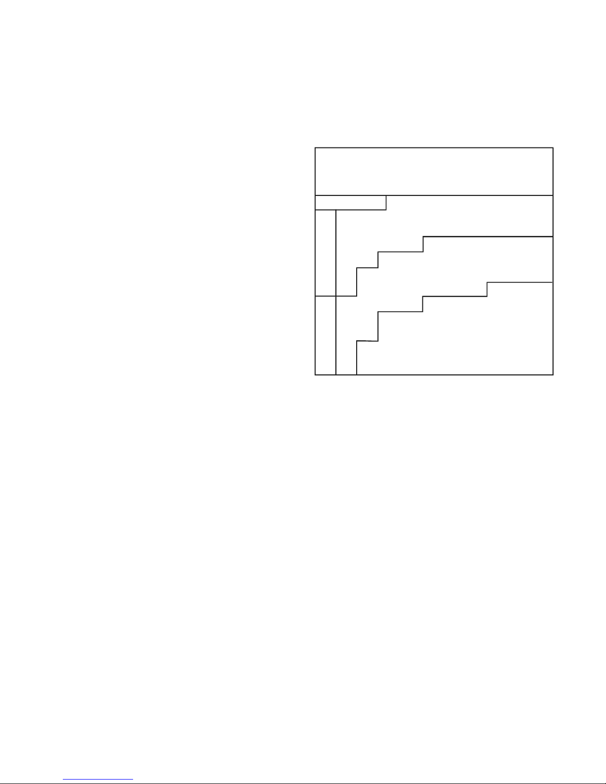
Centaur operators should be aware of the wind chill factor.
Dress warmly and make sure exposed skin is protected. Pay
particular attention that young passengers are properly dressed
with their hands and faces well protected.
WIND CHILL
Wind Speed
km/h 8 16 24 32 40 48 56 64
Actual Temp.(C)
-8
-2
0
-14
-7
-5
-20
-12
-10
-26
-18
-15
-32
-23
-20
-38
-28
-25
-45
-33
-30
-51
-39
-35
-57
-44
-40
-63
-49
-45
-69
-54
-50
-11
-18
-25
-32
-38
-45
-52
-59
-65
-72
-79
-14
-21
-28
-35
-43
-50
-57
-64
-71
-78
-85
-16
-23
-31
-38
-46
-53
-61
-68
-75
-83
-90
-17
-25
-33
-40
-48
-56
-63
-71
-79
-86
-94
-19
-26
-34
-42
-50
-57
-65
-73
-81
-89
-96
-19
-27
-35
-43
-51
-59
-67
-75
-83
-90
-98
Gradually
Increasing
Danger
Dangerou
Extremely
Dangerou
1.4 MODEL IDENTIFICATION
The trouble-shooting chart (Section 8) contains information
for locating and correcting mechanical problems. In many
cases, potential problems can be identified by unusual noises,
sluggishness or vibration, before they result in a breakdown.
Refer to the chart to identify these symptoms. T ake immediate corrective action or take the vehicle to a CENT AUR dealer
for service.
This manual does not provide detailed maintenance or servicing information for the engine. Refer to the engine manufacturer’s manual (supplied with each CENTAUR) for important warranty, service and operating information.
If the engine requires servicing, take the vehicle to an authorized engine service outlet.
1.3 WIND CHILL FACTOR
Why does it feel much colder outdoors on a windy day than
when there’s no wind, especially in winter? The cooling effect of the wind makes it feel like it’s colder than it really is.
This combined effect of wind and low temperature is known
as the “wind chill factor”.
The vehicle identification plate is fastened to the upper frame
to the right of the passenger’s knee. The model and serial
numbers are stamped into it.
1
Page 10

SECTION 1
GENERAL INFORMATION
Carefully observe the maximum load capacity for your vehicle on land and in water as listed in the following:
Model CENTAUR-G
Engine Make DM 950 G (Gasoline)
Briggs & Stratton Daihatsu
Type Naturally aspirated gasoline, in-line
CENTAUR-DT
DM 950 DT (Turbo Diesel)
Briggs & Stratton Daihatsu
Turbo Diesel, in-line 3 Cylinder, 4 cycle, liquid cooled
3 cylinder, 4 cycle, liquid cooled
Displacement 952 cc (58 cu. in.)
Horsepower 31 @ governed 3800 rpm
Torque 50.5 ft. lbs. @ 2200 rpm.
Electrical 12 volt, 60 amp alternator, 600 CCA
battery , dash mounted manual choke
952 cc (58 cu. in.)
31 @ governed 3800 rpm
55 ft. lbs. @ 2400 rpm.
12 volt, 60 amp alternator, 950 CCA battery, dash
mounted glow-plug-on and water-in fuel indicators
Engine Option 34 hp @ governed 3800 rpm 34 hp @ governed 3800 rpm
Torque 55 ft./lbs. @ 2200 rpm 58 ft./lbs. @ 2400 rpm
Brakes Foot pedal operated hydraulic disc brakes with hand lever operated mechanical parking brake.
Steering Hydrostatic skid steering.
Driver Controls Conventional automotive type steering wheel, brake pedal and foot throttle; dash mounted key
operated ignition/starter switch, high/low beam headlamp switch, tachometer/hourmeter, fuel level
and coolant temperature gauges; warning lights for low oil pressure and low electrical charge rate.
Clutch & Transmission Continuously variable belt driven torque converter (CVT). High and low range forward, neutral
and reverse transmission controlled by a conventional shift pattern range selector.
Final Drive System RC80 roller chains from transmission to eight 1.59" (40mm) diameter axles. Automatically ad-
justed tensioner for each drive chain. Tapered roller bearings in an oil bath support each axle.
Frame Powder coated, 3 inch tubular steel, lower body support pan, welded construction. FEA analyzed
for strength and durability.
Body Vacuum formed lower hull and standard full skid plate formed from high density polyethylene
(HDPE)
Load Capacity 1500 lbs/680 kg on land - 700 lbs/320 kg in water.
Towing Capacity* 2000 lbs/907 kg of drawbar pull.
Seating Capacity Front bench seat for two persons on land/two persons on water.
Fuel Capacity 12.6 U.S. gal./48 litres providing approx. 10 hours of operation
Speed** 28 mph/45 km/h on land - 2.5 mph/4 km/h on water
Shipping Weight 2100 lb/950 kg
Tires Goodyear Rawhide III AT25 x 11.50 - 9 NHS
Vehicle Weight 2100 lbs/950 kg Unladen, 2420 lbs/1 100 kg Unladen with Multi-purpose tracks, 3600 lbs/1633 kg
Laden
Max Total Vehicle Weight 3600 lbs/1633 kg. Includes everything: vehicle, accessories, operator, fuel, etc.
Ground Pressure Tires: Zero Penetration 5 PSI/ 34 kPa
Multi-purpose Tracks: Zero Penetration 1.5 PSI/ 10 kPa Laden: 2.2 PSI/ 15 kPa
3” of Penetration 1.0 PSI/ 6.8 kPa Laden: 1.4 PSI/ 9.5 kPa
Snow Tracks: Zero Penetration 0.7 PSI/ 4.8 kPa Laden: 1.0 PSI/ 6.8 kPa
3” of Penetration 0.6 PSI/ 4.1 kPa Laden: 0.9 PSI/ 6.1 kPa
Ground Clearance 8"/200 mm to centre of lower body
Operating Conditions All weather, all terrain, -40
o
F to +104oF (-40oC to + 40oC)
Transport Truck, trailer or helicopter lift
* Towing capacity is approximate and depends on type of surface, load on vehicle as well as incline.
** All speeds are approximate and depend on conditions.
Design and specifications subject to change without notice. Options may not be exactly as shown. Please visit us at www.Centaur8x8.ca and www.odg.com for
updated information.
2
Page 11
GENERAL INFORMATION
1.4.1 Centaur Vehicle Capacity
Vehicle capacity includes occupants, cargo, fuel, and
all accessories. Capacity for occupants and cargo is
reduced by the weight of accessories as shown in the
chart below.
SECTION 1
Do NOT use a Centaur on water when equipped with a
snow plow, dump box or any tracks. The incr eased weight
of the snow plow out front, the dump box or tracks, will
make the Centaur unstable and could cause the vehicle
to capsize, causing injury or drowning to the driver and
passengers.
A vailable vehicle capacity must be reduced if your vehicle is
equipped with any accessories. Reduce the available capacity by the total weight of accessories fitted to your vehicle.
Reduce By
Accessory On On
On Vehicle Land Water
Cab Heater 20 lbs. (9 kg) 20 lbs. (9 kg)
Winch Kit 45 (21) 45 (21)
Brush Guard 20 (9) 20 (9)
Cargo Liner 30 (14) 30 (14)
Dump Box 240 (109) SEE WARNING
Snow Plow 150 (68) SEE WARNING
Multi-Purpose Tracks 310 (141) SEE WARNING
Winter Tracks 515 (234) SEE WARNING
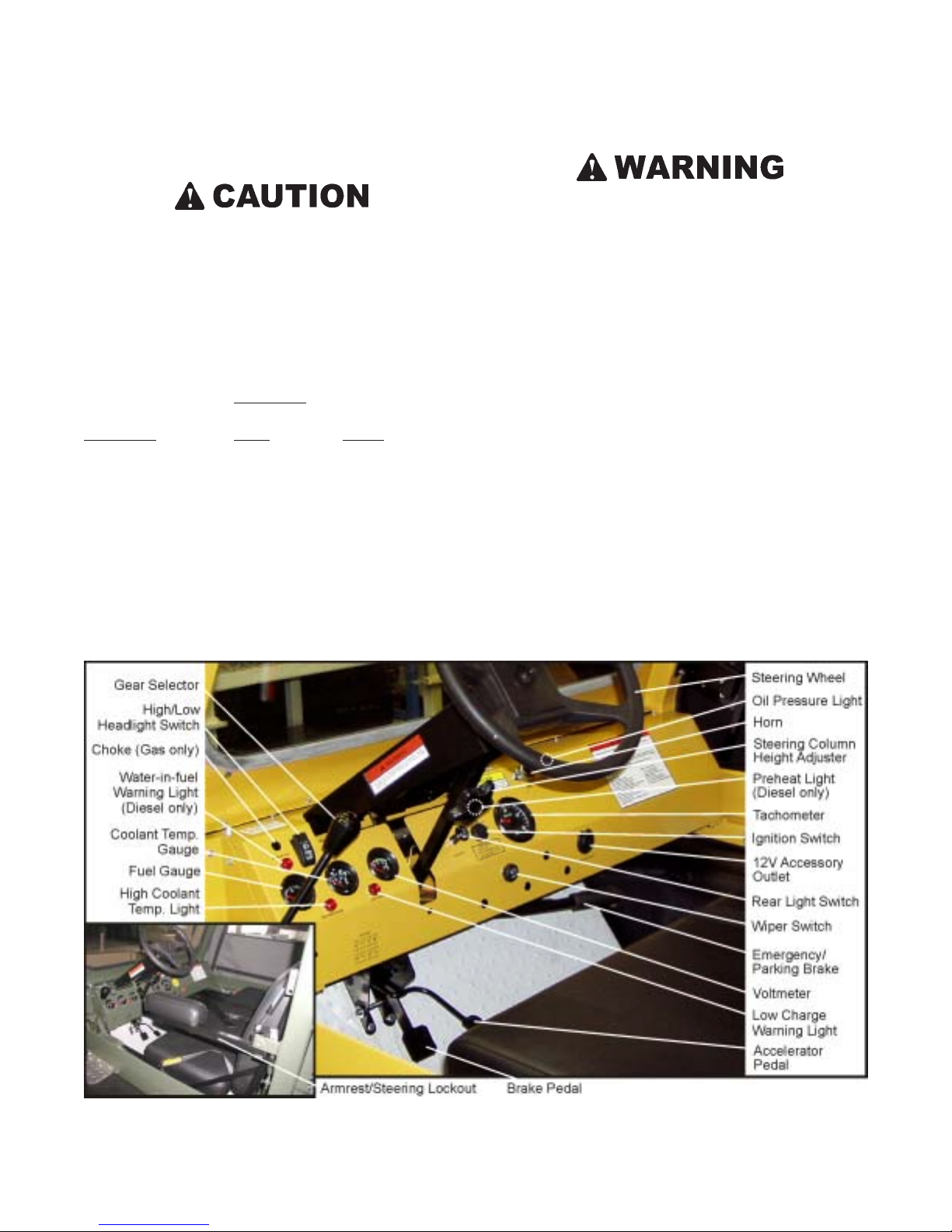
1.5 IDENTIFICATION AND LOCATION OF CONTROLS
1.6 CE MARKED CENTAURS
CE marked Centaurs include:
• CE marked serial number label
• horn, activated from driver’s compartment
• the weighted root mean square value for vibration of
the vehicle does not exceed 2.5 m/s
2
• the weighted root mean square value for vibration to
which the body is subjected does not exceed 0.5 m/s
• airborne noise emissions do not exceed:
Drivers position, stationary - 95.7 dB(A) @ 3800 rpm
Drivers position, stationary - 104.4 dB(C) @ 3800 rpm
2
3
Page 12
SECTION 1
GENERAL INFORMATION
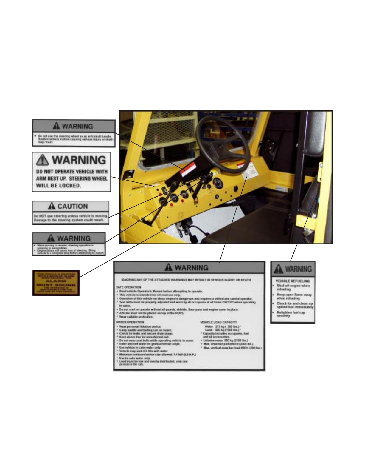
1.7 INFORMATION LABELS
There are labels on all models which indicate operating hazards and provide special operating instructions. Information about
the operation of the vehicle, correct fueling procedures, and steering system use has been provided on distinctive yellow and
black labels fastened to the various locations on the CENTAUR.
Figure 1.1 Location of Information Labels
4
Page 13

SECTION 2
GENERAL OPERATING INFORMATION
2.1 NEW VEHICLE “BREAK-IN” PROCEDURE
To obtain long term, trouble free service from your vehicle,
observe the following break-in guidelines:
1. Vary the speed of the vehicle for the first tank of fuel.
Avoid full power during break-in period.
2. Check engine and transmission oil levels daily during
break-in period.
3. Change the transmission oil after initial 25 hours of op-
eration. Failure to do so can result in damage to the transmission bearings or gear surfaces. Refer to Section 6.2.2
for transmission oil changing instructions.
4. Change the engine oil after the first 25 hours of opera-
tion. Refer to Section 6.1.3 of this manual for oil change
information.
5. Never overload your vehicle. Trying to steer an over-
loaded vehicle can over pressurize and damage the steering system. This will lead to a loss of steering control.
Overloading the vehicle can lead to premature steering
system failure and costly damage to drive chains, axles
or bearings. Follow the recommended load capacity for
the vehicle listed in Section 1.4.
2.2 PRE-OPERATION CHECKS
Carefully follow the engine manufacturer’s recommended preoperation/daily checks as well as the following:
1. Check the fuel level on the gauge.
2. Check the air pressure in all tires. All tires should be the
same pressure. For light use with low payloads pressurize to 5 psi (24 kPa). For heavy use with high loads use
up to 7 psi (48 kPa.)
3. Test the operation of the gas pedal by pressing to the
floor and releasing it. The throttle must operate smoothly
and return automatically to the fully closed position.
4. Test the operation of the steering lockout by lowering
the driver’s armrest. The steering wheel should turn freely
either way but be locked in the centre position when the
armrest is in the raised position.
tions. Clear any debris that has accumulated.
2.3 CARRYING PASSENGERS AND CARGO
1. Keep cargo as low as possible and evenly distributed.
2. Use extreme CAUTION when negotiating inclines with
a loaded vehicle. Heavy loads and high loads decrease
the stability of the vehicle and may cause it to roll. Be
prepared to shift occupant weight and load forward or
have passengers get out of the vehicle to climb an incline.
3. Secure cargo to prevent it from shifting while driving.
2.4 FUELING THE VEHICLE
Gasoline and diesel fuel are extremely flammable and
can explode under certain conditions. Do not add fuel
while the engine is running or hot. If fuel is spilled in,
on or around the vehicle, wipe it up immediately . Flush
out any fuel spilled in the vehicle with water and allow
it to drain out through the drain plug holes. Do not
smoke when filling the fuel tank.
The Centaur is equipped with a 48 litre (10.6 Imp. Gal., 12.7
U.S. Gal.) polyethelene fuel tank located underneath the driver’s seat. Depending on loading and driving conditions, a
Centaur can be driven for 7 to 12 hours on one tank of fuel.
V erify your vehicle’ s actual fuel consumption before attempt-
ing any long trips. Never travel in remote areas or set out on
long trips without a full tank of fuel and adequate spare fuel
stored in approved watertight fuel containers.
The fuel filler neck and fuel cap are located on the left side of
the vehicle behind the driver’s seat. Replace the fuel cap if
fuel leakage occurs, or if moisture is detected in the fuel. Use
ODG Part No. 126-46 fuel cap.
Never fill the tank to the point where the fuel level rises into
the filler neck. If the tank is overfilled, heat may cause the
fuel to expand and overflow through the vent.
Portable fuel containers may contain contaminants (dirt, water, etc.) that will cause engine operating problems. Use only
clean, approved fuel containers.
5. Check the brake travel by pressing on the pedal. See
Section 7.3.4 for proper adjustment details.
6. Check the engine intake and exhaust screen for obstruc-
After filling the fuel tank, be sure the fuel cap is replaced
securely . Do not drive the vehicle unless the fuel cap is properly in place.
5
Page 14

SECTION 2
GENERAL OPERATING INFORMATION
Never use untreated gasoline that has been stored for more
than 45 days. Stale gasoline can cause gum deposits to form
in the fuel lines and carburetor. These deposits clog the fuel
system and cause engine starting and operating problems.
When storing the CENTAUR for 45 days or more, use ODG
Part No. 125-85 Fuel Stabilizer to treat fuel in the fuel tank
and fuel containers.
Do not use Bio Diesel with Parker Superflex-FI fuel hose
equipped machines. Please contact manufacturer for
alternative fuel hoses.
*Machines built before May '06 used fuel lines NOT
compatible with bio-diesel fuel.
Centaur 950 and 954 - Gasoline
Use clean, fresh, unleaded gasoline with a minimum of 85
octane. Purchase fuel in quantity that can be used within 30
days to assure fuel freshness. W e recommend the use of Briggs
& Stratton gasoline additive; ODG part no. 127-77. Leaded
gasoline may be used if it is commercially available and
unleaded is unavailable.
Keep fuel tank full. Do not over-fill. Allow space in tank for
fuel expansion. Check for fuel leaks at fuel filter, injector
pump, fuel lines, etc.
If the fuel tank does run dry , use the priming pump on the fuel
filter to bleed the air from the fuel line then attempt to restart
the engine. You may have to bleed the system several times
in order to restart engine.
2.5 VENTED FUEL SYSTEM
Centaur models have fuel tanks that are vented through a special hose connected to the filler neck assembly that runs along
the firewall to a position up under the engine cover.
Note: Some fuels, called oxygenated or reformulated
gasolines, are gasolines blended with alcohols or ethers. Excessive amounts of these blends can damage the fuel system
or cause performance problems. Do not use gasoline which
contains Methanol. If any undesirable operating symptoms
occur, use gasoline with a lower percentage of alcohol or ether .
Keep fuel tank full. Do not over-fill fuel tank. Allow space
for fuel expansion. Check for fuel leaks at fuel filter,
carburetor, fuel pump, etc.
Centaur 950DT - Diesel Turbo
Use clean, fresh diesel fuel with a minimum of 40 cetane.
Purchase fuel in quantity that can be used within 30 days to
assure fuel freshness.
Do not use kerosene or gasoline instead of diesel fuel.
Failure to observe this caution will damage the engine
and void manufactures warranty.
6
Page 15

SECTION 3
OPERATING INSTRUCTIONS
3.1 STEERING
The steering wheel is used to turn the vehicle whenever the
engine is running. When moving forward, steering is similar
to an automobile. When moving in reverse, steering is opposite to an automobile, similar to backing up a trailer.
When moving in reverse, steering operation is opposite
to automobiles. Practice driving backwards before taking the vehicle off road.
The steering system works whenever the engine is running,
even when the gear selector is in neutral. The CENT AUR is a
skid steer vehicle. During a turn, the rear of the vehicle swings
outward as the vehicle pivots on the tires on the inside of the
turn. To make a right hand turn, the rear of the vehicle skids
out to the left. To make a left hand turn, the rear of the vehicle skids out to the right.
3.2 BRAKES
The Centaur has a foot operated brake pedal. To stop the
vehicle, press firmly on the brake pedal.
3.3 PARKING/EMERGENCY BRAKE
The Centaur is equipped with a parking/emergency brake.
The lever is located midpoint under the dash and is activated
by pulling towards the driver. Release the brake by
pushing
the button on the end of the lever and pushing the lever as far
forward as possible.
3.4 THROTTLE CONTROL
Vehicle speed is controlled by the accelerator pedal. To increase vehicle speed, press on the accelerator pedal. To decrease vehicle speed, remove pressure on the accelerator pedal.
3.5 STARTING PROCEDURE
When turning, the back of the vehicle swings to the opposite direction of the turn. Always take care to avoid
hitting persons or objects with the rear of the vehicle!
Serious injury or death can result!
The steering system is powered by a hydrostatic transmission
and works best when engine r.p.m. is higher than at idle. A void
turning the steering wheel when engine is idling.
Do NOT use steering unless vehicle is moving. Do NOT
use steering to assist in entering the vehicle. Damage to
the steering system could result.
Centaur vehicles built after August 2001 have a steering lockout system. The armrest on the driver’s side is mechanically
linked to the steering control. The steering wheel is locked in
the center position when the armrest is in the raised position.
When the armrest is in the lowered position, the steering is
unlocked and ready for use.
Never start or run the engine in a closed building or
confined area. Engine exhaust gases contain poisonous
carbon monoxide. Carbon monoxide is odourless, colourless and can cause serious personal injury or death.
All Centaur models are equipped with key operated, electric
start systems.
Centaur vehicles built after December 2001 have a neutral
safety switch that prevents the vehicle from being started
unless the vehicle gear selector is in neutral.
3.5.1 Gasoline Powered
1. Shift the transmission into neutral.
2. Use the choke if the engine is cold. Do not press down
on the accelerator pedal if using the choke.
3. Turn the key to the “START” position.
Ensure armrest is lowered and steering wheel moves
freely befor e driving the Centaur. If the steering lockout
feature malfunctions, steering will be impaired which
could cause an accident resulting in serious injury or
death.
7
Page 16
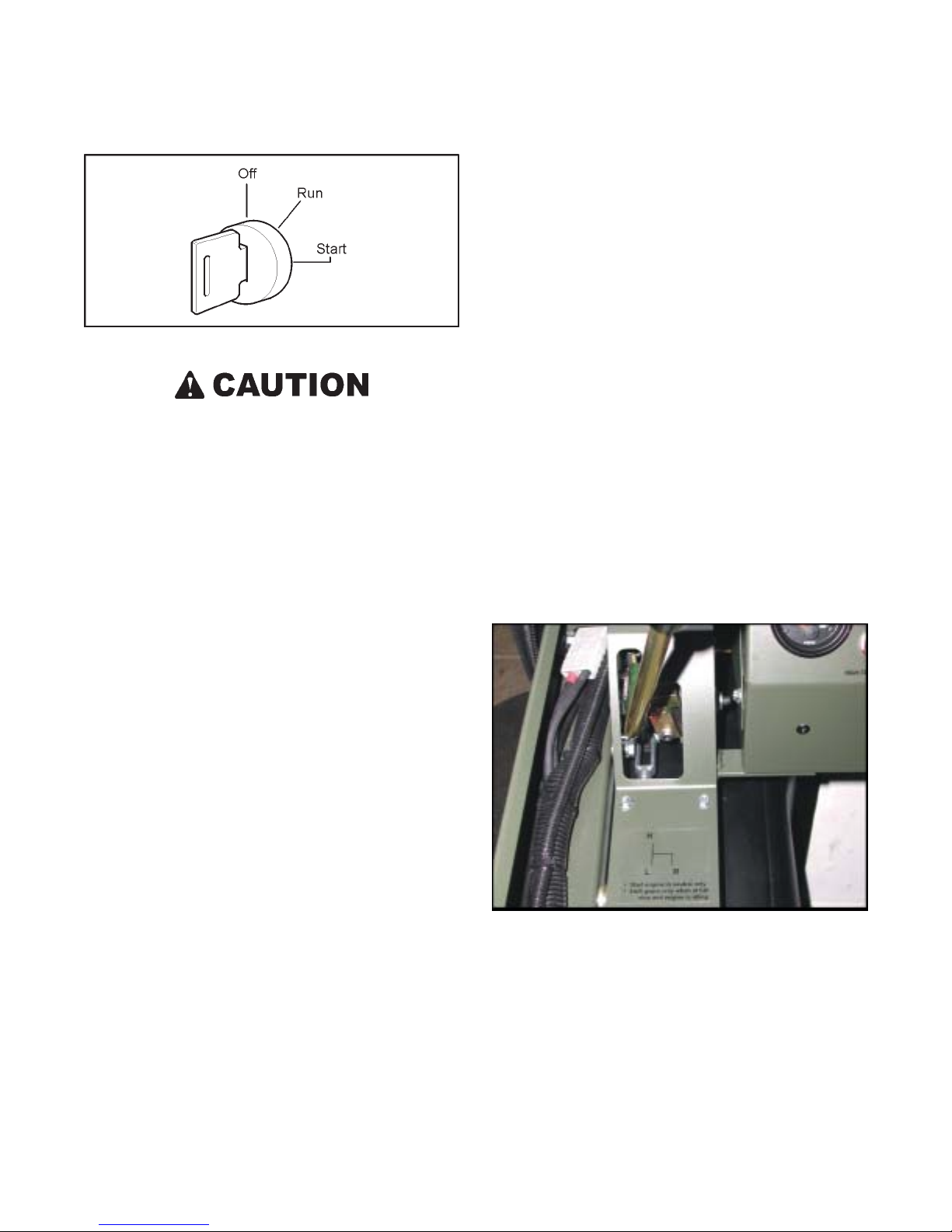
SECTION 3
OPERATING INSTRUCTIONS
and turn ignition switch to the “OFF” position. Always remove key from ignition switch when leaving the vehicle unattended.
3.7 SELECTING AND CHANGING TRANSMISSION
GEARS
The CENTAUR is equipped with a four position transmission. The gearshift lever is located to the left of the dash.
Figure 3-1. Ignition Switch
Do not operate the starter continuously for more than 5
seconds or the starter may overheat. Wait 30 seconds
between each operation of starter to let it cool and the
battery power recover. Never attempt to restart the engine until it completely stops. Always remove key from
switch when leaving vehicle unattended or when vehicle is not in use.
4. Release the key as soon as the engine starts: the key will
automatically return to the “RUN” position.
5. Push the choke in halfway after the engine starts, and
push it in all the way as the engine warms up.
6. If the engine fails to start, refer to the trouble-shooting
chart in Section 8 for corrective action.
3.5.2 Diesel Powered
1. Shift the transmission into neutral.
* R (Reverse) - for backing up the vehicle
* Neutral - for starting the engine or idling
* L (Low) - for use when extra pulling power or very low
speed is required in rough terrain.
* H (High) - for general use at normal operating speeds.
Inside the transmission, there is a synchronizer system or
clutch brake on the input shaft to allow for easier and more
accurate shifts. When you apply force to the shift lever, it is
transmitted through push/pull cables to the transmission,
where it forces a gear to slide on the input shaft. The movement of the gear on the shaft is restricted by springs and balls
within the input shaft so that extra force must be applied, allowing the synchronizer to brake the rotating shaft to a stop.
This reduces gear grinding during shifting.
2. Turn the key to the “ON” position. The “DIESEL
PREHEAT” light will come on for approximately five
seconds.
3. When the “DIESEL PREHEAT” light goes out, turn the
key to the “START” position.
4. Release the key as soon as the engine starts; the key will
automatically return to the “RUN” position.
5. If the engine fails to start, refer to the trouble-shooting
chart in Section 8 for corrective action.
3.6 STOPPING THE ENGINE
Bring the vehicle to a complete stop. Release the accelerator
pedal. Ensure that the steering wheel is positioned such that
the vehicle doesn’t turn. Let the engine speed return to idle
Figure 3-2. Direction of gearshift travel and gear positions.
If the gear does not easily engage, it is possible that the teeth
are clashing directly. If this is the case, pushing harder may
not help. The input shaft must be allowed to start turning again
and the shift attempt made over.
The shift box is designed to allow one lever to be used to shift
both high and low gears and reverse. There is a neutral position in which the lever can be moved side to side. The mechanism inside the transmission does not allow two gears to be
engaged at one time. Access to low, high, or reverse is only
8
Page 17

SECTION 3
OPERATING INSTRUCTIONS
possible from the neutral position. Shifting works best when
the engine is running. To shift into high gear after the engine
is running:
1. Ensure that the lever is in neutral. Pause for a few seconds, and then;
2. Push firmly and quickly into the high gear position.
This works best if the brakes are NOT applied. If this doesn’t
work, put the lever back into neutral, step on the gas pedal to
rev the engine briefly (1500 rpm), let the engine idle down,
and then try the shift again. Repeat until it slides into gear.
If vehicle shifts hard into high, try shifting first into low ,
then into high and if the brakes are applied, the vehicle
should shift better.
The technique to shift into low gear is identical to shifting
into high.
T o shift into reverse, move the lever to the right and pull down
firmly. Less force is required to shift into reverse. Reverse
does not have a synchronizer so it is very important that the
engine is idling. If reverse gear does not engage the first time,
use the same technique as for shifting into high and low.
Do not attempt to move the gearshift from the neutral
starting position until the engine idles down completely.
The Centaur is equipped with an automatic clutch that
is activated by engine speed. If the engine idle speed is
too high, the transmission will grind during gear engagement.
3.8 HEADLIGHTS
The CENTAUR is equipped with 4 headlights that are operated through the dash mounted light switch. T o turn the lights
on, push the light switch forward and down. The first position turns on two lights with a flood pattern. The second position turns on the other two driving lights in addition to the
two flood lights.
Do not leave the lights on for any length of time when
the engine is not running. Leaving them on will drain
the battery.
9
Page 18

4.1 DRIVING STRAIGHT AHEAD
SECTION 4
DRIVING PROCEDURES
Ensure the driver’s armrest (if equipped) is in the lowered
position. Shift the transmission into LOW or HIGH. Press
down on the accelerator pedal slowly until the clutch system
engages and the vehicle moves forward.
4.2 STOPPING THE VEHICLE
Reduce pressure on the accelerator pedal. Press carefully on
the brake pedal.
Do not apply brakes abruptly. The brakes are very effective and sudden braking may cause you or your passengers to be thrown from the vehicle and could result
in serious injury or death. Never use excessive force on
the brake pedal to apply the brakes. This can cause
tremendous pressure in the master cylinder and brake
caliper, resulting in component failure.
When driving the vehicle, do not “ride” the brakes. Keep
your foot off the brake pedal unless you are stopping the vehicle.
4.3 TURNING THE VEHICLE
When turning in reverse, steering operation is opposite
to automobiles, similar to backing up a trailer.
The Centaur is a skid steer vehicle. The rear of the vehicle
swings outward during a turn. Always take precautions when
making turns to avoid hitting persons or objects.
The steering system is powered by a hydrostatic transmission
and works best when engine r.p.m. is higher than at idle. A void
turning the steering wheel when engine is idling.
Do not use steering unless vehicle is moving. Damage
to the steering system could result.
4.4 BACKING THE VEHICLE UP
With the engine at idle, shift the transmission into reverse.
Press on the accelerator pedal slowly until the clutch system
engages and the vehicle moves backward. Increase speed by
gradually increasing pressure on the accelerator pedal.
4.4.1 Turning The Vehicle While Backing Up
Carefully practice backing up and turning in an open area
until you become accustomed to this procedure. Take precautions to avoid hitting persons or objects.
10
Page 19

SECTION 5
DRIVING PROCEDURES IN UNUSUAL CONDITIONS
5.1 REMOTE AREA USE
When traveling in remote areas or when traveling long distances, the following items are essential:
• a first aid kit
• a complete survival kit
• protective clothing and footwear
• waterproof safety matches
• candles
• emergency flares
• communications equipment
• adequate fuel supply in approved, watertight containers
• fire extinguisher
• back-up battery
• basic mechanic’s tools and Centaur spare parts
Before venturing into remote areas, carry out all inspections,
adjustments and lubrication checks detailed in this manual.
Do not proceed unless your vehicle is in good working condition.
Inform someone of your departure and return plans and your
route so that help can be dispatched if you do not return as
scheduled. Do not travel into a remote area alone.
Choose your equipment and supplies to meet the climate and
terrain conditions that you may encounter. Practice safe driving habits when traveling in remote areas. Avoid terrain that
may be impassable.
5.2 ANGLE OF OPERATION
When operating the CENTAUR on an angle, (up and down
hills or across uneven terrain that causes the vehicle to tilt in
any direction) the engine and transmission oil levels are affected. If the engine oil level falls below the oil pump intake
or if the transmission oil level falls below the hydrostatic transmission intake port, damage will occur because of inadequate
lubrication. To avoid premature engine or hydrostatic transmission damage and costly repairs:
• Do not operate your engine continuously on angles or
inclines that are greater than 30 degrees in any direction.
• Make sure the engine oil level is near the “full” mark
(However, do not overfill.)
• Make sure the transmission oil level is between the two
marks on the dipstick.
5.3 UPHILL OPERATION
Never accelerate or brake suddenly while driving up or
down a hill. Sudden acceleration or braking can cause
the vehicle to roll over, causing serious personal injury
or death.
Never attempt to turn the vehicle around on a steep hill
or grade. Turning the vehicle around on a hill can result in the vehicle rolling over and can r esult in serious
injury or death.
Approach the hill head on to minimize the possibility of sliding sideways or rolling over. Accelerate slowly to prevent
loss of traction. When traction is lost, the vehicle may slide
sideways or backwards. If this occurs, apply the brakes gently and evenly to stop the slide. Allow the vehicle to coast
back down to the bottom of the hill by carefully releasing the
brakes.
Try to avoid steep hills. When a steep hill can’t be avoided,
be prepared to shift cargo forward to prevent the vehicle from
rolling over. As a general rule, driving up a steep hill greatly
increases the possibility of rolling over.
5.4 DOWNHILL OPERATION
Always approach the hill head on to minimize the possibility
of sliding sideways, or rolling over . Do not abruptly or forcefully apply brakes while travelling downhill. Sudden braking
can cause the vehicle to roll over frontwards. Use engine braking by selecting low range and keeping the engine speed up
just enough to keep the clutch engaged. If engine braking is
not sufficient to control downward vehicle speed, then gently
apply the brakes with your left foot while maintaining engine
speed with your right foot.
Avoid steep declines when possible. When a steep decline
cannot be avoided, shift cargo to the rear of the vehicle to
prevent the vehicle from rolling over. As a rule, driving the
vehicle down a steep decline greatly increases the possibility
of rolling over.
5.5 SIDE SLOPE OPERATION
Do not drive your vehicle across the side of a hill. Side slope
operation greatly increases the risk of rolling the vehicle over
sideways.
Prolonged side slope operation may cause engine damage.
Observe the engine angle of operation limitations in Section
5.2.
11
Page 20
SECTION 5
DRIVING PROCEDURES IN UNUSUAL CONDITIONS
5.6 AMPHIBIOUS OPERATION - GENERAL
The CENTAUR may sink if filled with water. If water
starts entering the vehicle, head to the nearest shore
immediately. Be prepared to abandon the vehicle if it
appears that the vehicle will fill with water before you
reach the shore. Be especially cautious when operating
a loaded vehicle (cargo and/or passengers) in water.
Observe the capacity limits.
Centaur vehicles are self-propelled, amphibious vehicles, capable of navigating calm water, provided the following precautions are observed:
1. Do not enter water if the vehicle is overloaded. Refer to
Section 1.4 of this manual for recommended load capacity in water.
2. Do not use seat belts or any passenger restraining device
while operating the Centaur in water. If an emergency
arises, you and your passengers may have to leave the
vehicle quickly.
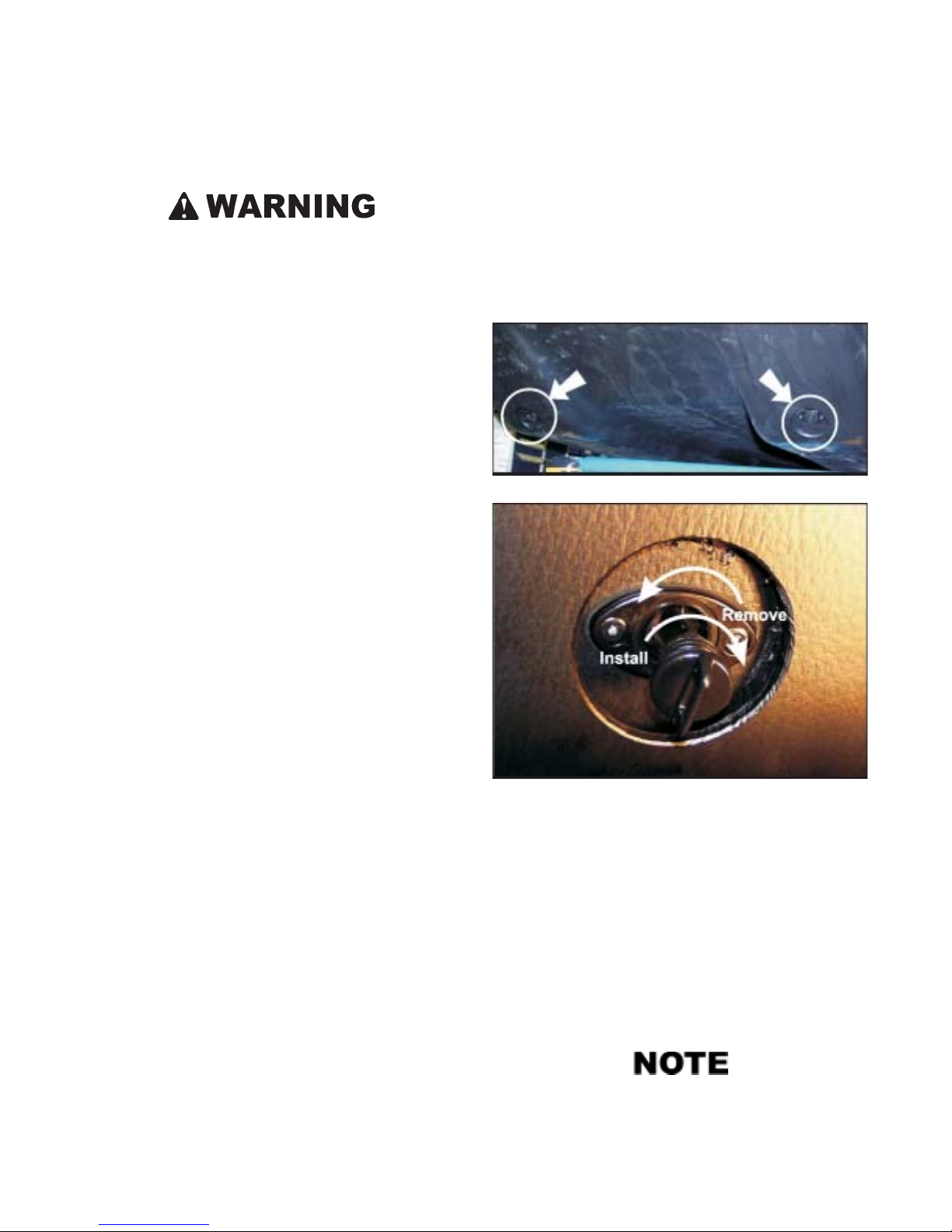
3. Make sure both drain plugs in the rear of the lower body
(Figure 5-1) are in place and properly tightened. To install, locate the drain plugs at the rear of the vehicle and
thread each drain plug in a clockwise direction into the
plug fitting ensuring a snug fit. Check the O-ring on drain
plug periodically. When removed, each drain plug remains attached to the hole opening to prevent loss or
misplacement of the plug while the vehicle is draining.
(Figure 5-2).
Figure 5-1. Location of the drain plugs.
3. Do not attempt to cross large bodies of water . S tay close
to the shore in case an emergency arises and you have to
leave the water.
4. Do not attempt to navigate any body of water with a strong
current. Avoid water operation under windy conditions.
5. Use extra caution when operating the Centaur in cold
water . If the vehicle upsets or swamps, exposure in cold
water significantly reduces the chance of survival.
6. Be prepared to adjust the position of cargo and passengers so the vehicle floats level.
7. Care must be taken when encountering submerged obstacles that may upset the vehicle.
Observe the following safety precautions BEFORE entering
the water:
1. All occupants must wear an approved personal flotation
device (PFD) or life jacket while traveling in water.
2. Equip the vehicle with a paddle and bailing can. Optional
bilge pump kits (Part No. 849-146) are available from
your Centaur dealer and are recommended for water operation.
Figure 5-2. Removing and installing the drain plugs.
4. Visually check the lower body of the vehicle for cuts,
punctures or holes that will allow water to enter the vehicle.
5. Make sure that any cargo in the rear of the vehicle is
evenly distributed.
6. Periodically inspect the fit of the axle housings to the
lower body to ensure they are water tight. If there are
signs of water leaking into the lower body, take corrective action before entering water again.
Always observe the recognized rules of boating while
traveling in water.
12
Page 21

SECTION 5
DRIVING PROCEDURES IN UNUSUAL CONDITIONS
5.6.1 Entering the Water
The point of entry should be free of rocks, stumps and other
obstacles. Enter the water from a firm, gradual slope whenever possible. With the wheels partially submerged but still
in contact with the bottom, stop and check thoroughly for
water entering the lower body.
If a leak is detected, drive back onto shore. Drain the vehicle
and repair the leak before re-entering the water.
5.6.2 Driving Procedures in Water
After the vehicle is floating evenly on the water, press the
accelerator pedal to increase speed. Use only part throttle
when traveling through water. Full throttle only results in
excessive turbulence, not higher speeds.
The vehicle is steered by turning the steering wheel left or
right. Turning can be improved by leaning. The turning radius is somewhat greater in water, and the vehicle does not
respond to changes in direction as quickly as it does on land.
The vehicle is propelled forward through the water by the
web of the tires as they rotate. T o back up in water , release the
throttle, shift the transmission into neutral, and use a paddle.
5.7 WINTER OPERATION
Follow these precautions when operating the Centaur in winter conditions:
• Equip the vehicle for remote area use, as listed in Section 5.1.
• Keep the battery fully charged and in good condition.
• Use the recommended winter grade of engine oil.
• Do not allow water or snow to accumulate in the vehicle.
Snow may melt during operation of the vehicle, collect
in the lower body and freeze around the chains and final
drive components, immobilizing the vehicle.
• Store the vehicle indoors or under cover.
• Equip your vehicle with snow tracks for travel over deep
snow.
• Steep, snow-covered or icy hills may be more difficult to
ascend or descend.
• Never travel alone into a remote area. Leave your route
and arrival plans with someone who can send help if you
fail to arrive as planned.
5.7.1 Use on Ice Covered Bodies of Water
A void rocks, stumps or other obstacles that are below the surface of the water. Striking these obstacles may damage the
bottom or upset the vehicle.
If your vehicle begins to fill with water, immediately head to
the nearest shore. Get the vehicle out of the water and drain
it by removing both rear drain plugs. Correct the leak before
entering the water again.
Do not leave the vehicle in water for extended periods
of time. W ater could enter the axle seals and cause damage to the axle bearings.
5.6.3 Driving Out of Water
When driving out of water, choose an area of the shore that is
reasonably flat and free of rocks, stumps and other obstacles.
Steer the vehicle so that both front wheels reach the shore at
the same time. Accelerate slowly until the vehicle is out of
the water.
Using the CENTAUR on ice-covered bodies of water is
potentially hazardous. Use extreme caution. Exposure
to cold water reduces a person’s chance of survival.
Protective clothing, such as a marine survival suit will
significantly decrease the effect of exposure in frigid
water.
Before venturing out onto ice-covered bodies of water, it is
extremely important to:
• Check the ice thickness and condition to be sure it will
support the vehicle.
• Take all precautions as in Section 5.6, particularly paragraph 3 referring to drain plugs.
• Consider taking along a cellular telephone or similar device to call for help in case of emergency.
If the vehicle breaks through the ice, it will float in the water,
provided that there are no leaks in the body, the drain plugs
are in place and vehicle is not taking on water through any
body openings. However, there is a risk of the vehicle tipping, particularly if the load is unbalanced. Be prepared to
shift occupants’ weight for balance.
Getting back onto safe ice depends on various conditions and
the expertise of the driver. Be especially careful to prevent
water from entering the vehicle.
13
Page 22

SECTION 5
DRIVING PROCEDURES IN UNUSUAL CONDITIONS
• Balance the cargo and passenger load.
• Keep openings above the water line.
• Keep the bilge pump running.
• Winch the vehicle out.
• Back onto ice, as the back end is lighter and floats higher
in the water.
• Avoid getting the wheels on only one side onto the ice
surface as water could enter over the opposite side of the
vehicle.
• Avoid turning as the Centaur is climbing out to avoid
vehicle tip-over.
• Break the thin ice around the vehicle with the paddle
until there is firm ice for the vehicle to climb onto.
• Be wary of currents which may pull the vehicle under
the ice.
If you feel that you may not be able to get the vehicle back
onto safe ice or land, you might consider staying put to await
rescue. This may be safer than trying to leave the vehicle to
walk over thin ice.
14
Page 23
OIL, FILTER AND LUBRICATION INFORMATION
6.1 ENGINE OIL INFORMATION
Detailed information on standard workshop and safety
procedures and general installation practices is not included in this manual. ODG assumes no responsibility
or liability for PERSONAL INJURY or VEHICLE DAMAGE which results from any procedure performed, including those procedures outlined her e. Before performing any procedur e, an individual must have determined
to his/her satisfaction that personal injury or vehicle
damage will not result fr om the procedure, working environment or tools selected.
6.1.1 Checking the Engine Oil Level
SECTION 6
Do not run the engine if the oil level is above the “F”
mark or below the “L” mark. Premature engine damage or total engine failure can occur when the oil level
is not properly maintained.
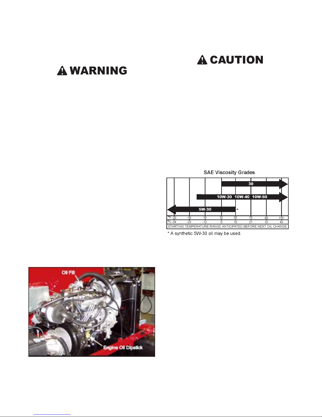
6.1.2 Recommended Engine Oil
Use a high quality detergent oil of API (American Petroleum
Institute) service class as listed below. Choose the correct
viscosity of oil for seasonal driving conditions. For the gasoline powered Centaur, use API service class “SH” or “SJ” or
higher. For diesel powered Centaur use API service class
“CF” or “CF-4”.
Check the engine oil level each day before operating the engine.
To check the oil during an operating period, shut the engine
off, let it cool down and allow the oil time to drain into the
sump before checking the oil level. Position the vehicle so
the engine is level.
The BRIGGS & STRATTON DAIHATSU engine (Figure 6-
1) is equipped with a dipstick and a separate oil filler cap. T o
check the oil level, clean the area around the dipstick before
removing. Remove the dipstick and wipe it with a clean cloth.
Re-insert the dipstick and push it all the way into the tube.
Remove the dipstick and check the oil level. The oil level
should be between the marks. If the level has dropped, add
oil to bring the level up to the “F” mark. DO NOT OVERFILL.
Oil capacity is approximately 3.3 litres, including the oil filter.
6.1.3 Changing Engine Oil
During the initial engine break-in period, change the oil after
the first 25 hours of operation. After the break-in period,
change the engine oil every 150 operating hours, or more frequently if the vehicle is operated in dusty or dirty conditions.
Draining the Engine Oil
Each engine is equipped with a drain plug for draining the
oil. The drain plug location is shown in the engine owner’s
manual. Drain the oil from the engine as follows:
Figure 6-1. Oil fill and level location
Briggs & Stratton Daihatsu engine
1. Start and warm up the engine so the oil will drain easily.
2. Level the vehicle so the oil will drain completely.
3. Place a suitable container under oil drain of engine and
remove drain plug with a wrench.
15
Page 24
OIL, FILTER AND LUBRICATION INFORMATION
There is limited space between the engine and transmission. Cut down an empty plastic container to the correct height so it will fit under the engine oil drain. Make
sure the container will hold the amount of oil in the engine.
A ziploc plastic bag makes a convenient oil container.
It conforms to the space available and can be closed
securely when the oil is drained, then lifted neatly out of
the engine compartment.
PLEASE DISPOSE OF WASTE OIL PROPERLY TO
CONSERVE OUR ENVIRONMENT.
SECTION 6
4. When all the oil has been drained from the engine, clean
and replace the drain plug. MAKE SURE it is properly
tightened before refilling the engine.
5. See Oil Filter Replacement in Section 6.3.3.
Refilling the Engine
Refill the engine through the oil fill with the correct amount
and grade of oil as indicated in Section 6.1.2. As you add oil,
frequently check the level with the dipstick. Do not overfill.
Start engine. Check for leaks. Stop the engine. Check the oil
level. Add oil only to the “F” mark on the dipstick.
6.2 TRANSMISSION OIL INFORMATION
6.2.1 Checking the Transmission Oil Level
Check the transmission oil level each day before operating
the Centaur. The Centaur is equipped with a transmission oil
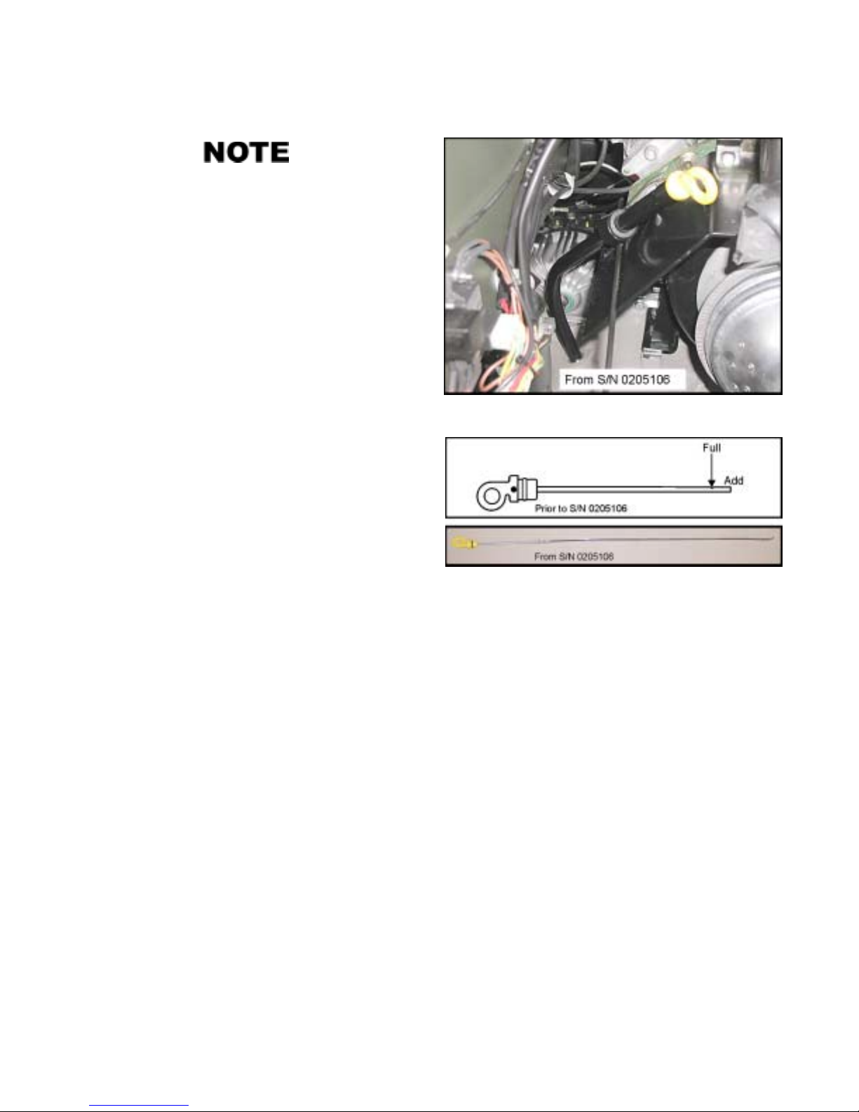
dipstick (Figure 6-2). Position the vehicle so the transmission is level. Clean the area around the dipstick before removing. Remove the dipstick by pulling up.
The transmission oil level should be even with the mark on
the dipstick as shown in Figure 6-3. Add Citgo Transguard
Tractor Hydraulic Fluid (or equivalent) through the transmission oil fill/dipstick hole until the transmission is filled to the
correct level. When the oil level is at the lower notch, approximately one litre can be added. DO NOT OVERFILL.
Replace the dipstick securely.
Figure 6-2. Location of Transmission Dipstick
Figure 6-3. Transmission Dipstick
6.2.2 Changing the Transmission Oil
Change the transmission oil after the first 25 hours of operation. After this, change the transmission oil every 150 operating hours. Drain the transmission oil using an oil change pump
accessory (Part No. 638-02) by drawing the oil through the
oil fill/dipstick hole. Dispose of the oil at a disposal site.
Refilling the Transmission
Refill the transmission through the oil fill/dipstick hole with
12 L of Citgo T ransguard T ractor Hydraulic Fluid (or equivalent). Alternately, Mobil Delvac 1, 5W30 synthetic oil may
be used,especially if operating the Centaur under extreme cold
or hot weather conditions; this Mobil oil may be used in the
engine also. Start the engine and run for a minute to fill the
oil filter and hydrostatic transmission. Check that the oil level
is even with the mark on the dipstick, after it has been seated
fully in the dipstick hole. DO NOT OVERFILL.
6.3 FILTER INFORMATION
6.3.1 Air Filter
The Centaur is equipped with a filter element housed in an air
cleaner assembly located above the clutch.
16
Page 25
SECTION 6
OIL, FILTER AND LUBRICATION INFORMATION
Check the paper air filter element every 100 hours of operation or more often under extremely dusty , dirty or wet conditions.
For instructions to remove, clean and replace the air filter
components, refer to the air cleaner section of the engine
owner’s manual.
6.3.2 Fuel Filter
950
The gasoline powered Centaur is equipped with an in-line
fuel filter (Part No. 125-64).
The fuel filter is located in the fuel hose, next to the fuel tank.
Replace the fuel filter after every 300 hours of operation or
once a year. T o replace the filter , loosen the gear clamps with
a standard screw driver and pull the rubber fuel lines off of
the filter. Install the new filter with the flow arrow pointing
toward the engine. Tighten the clamps securely. Start the en-
gine and check for fuel leaks.
950DT and 954DT
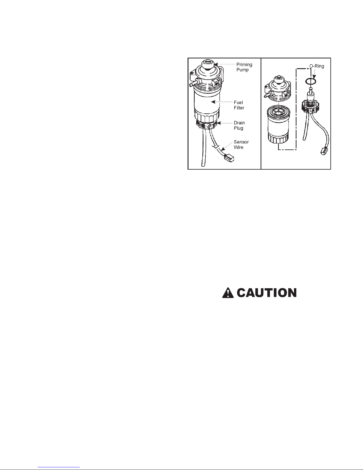
The diesel powered Centaur is equipped with a fuel filter assembly comprised of a replaceable element, water separator
bowl, and water level sensor.
If the fuel filter warning light comes on while engine is running, stop engine and drain water from fuel filter.
1. Stop engine.
2. Place a drain pan under fuel filter and loosen drain plug
approximately 1 turn.
3. Water should drain. If necessary, operate priming pump
to drain water, but only until fuel flows from filter.
Figure 6-4. Fuel Filter
4. Tighten drain plug. Bleed air from fuel line.
5. Start engine. Make sure warning light goes out. Check
for leaks.
To replace fuel filter element:
1. Disconnect sensor wire. Remove drain plug and discard
O-ring.
2. Remove fuel filter with filter wrench.
3. Screw new filter on by hand until gasket contacts housing. Then tighten 1/3 turn more.
4. Install drain plug with new O-ring. Connect sensor wire.
5. Bleed air from fuel line. Start engine and check for leaks.
Do not operate the fuel injector pump dry. Ensure the
pump is primed with fuel before starting to pr event damage to the pump.
6.3.3 Engine Oil Filter
During the initial engine break-in period, change the oil filter
(Part No. 126-95 for gas engines & No. 820314 for diesel)
when the oil is changed. After that, change the oil filter every
300 hours.
Before installing the new filter, lubricate the rubber filter gasket with fresh oil. Screw the filter on by hand until the gasket
contacts filter adapter. Tighten 1/2 to 3/4 turn more. Start
and run engine to check for oil leaks. Stop engine and recheck oil level. Add oil if required.
17
Page 26
SECTION 6
OIL, FILTER AND LUBRICATION INFORMATION
6.3.4 Transmission Oil Filter
The hydrostatic transmission is equipped with a disposable,
spin-on oil filter . Replace this filter with a new one whenever
transmission oil is changed (Part # 610-114).
Before installing the new filter, lubricate the rubber filter gasket with fresh oil. Screw the filter on by hand until the gasket
contacts filter adapter. Tighten 1/2 to 3/4 turn more. Start
and run engine to check for oil leaks. Stop engine and recheck oil level. Add oil if required.
6.4 LUBRICATION INFORMATION
6.4.1 General
The drive chains require regularly scheduled lubrication to
prevent premature wear and replacement. Use the recommended lubricants listed in this section and carefully observe
the recommended lubrication intervals.
6.4.2 Drive Chain Lubrication
Your Centaur is equipped with roller chains to each axle.
Lubricate the chains every 10 hours with Aerosol Chain Lube
(Part No. 125-86), or more frequently in dirty or wet conditions.
6.4.4 Axle Bearing Lubrication
Figure 6-5. Axle Assemblies
The Centaur axle assemblies are filled with 300ml of 80W90
Gear Lube HYP0Y-C. At 25 hours:
1. The oil level should be checked by removing the side
plug on each axle housing. Fill the axle assembly until
the oil is level with this hole.
2. The bottom plug should be removed to check for water
contamination. If water runs out or the oil has a milky
appearance, drain the oil and replace with 300 mL (10.2
ozs.) of 80W90 Gear Lube HYP0Y-C.
After every 100 hours of operation, remove all the drive chains
from the vehicle and clean them thoroughly in a suitable solvent, i.e. degreaser.
Never use gasoline as a cleaning solvent. Gasoline is
extremely flammable and can explode if ignited, causing serious personal injury.
Allow the chains to dry thoroughly, re-lubricate generously
with Chain Lube and re-install.
Refer to Section 7.2.3 of this manual for drive chain removal
and re-installation instructions.
6.4.3 Driven Clutch Maintenance
The driven clutch uses dry slide bushings and should not be
lubricated. A complete service of the clutch units is required
after every 300 hours of operation. To perform this procedure, the clutches must be disassembled. Special tools are
required to disassemble the clutch units. W e recommend that
you return your vehicle to a Centaur dealer to have the clutch
units serviced.
The oil in the axle housings should be replaced each 150 hours
of operation.
18
Page 27
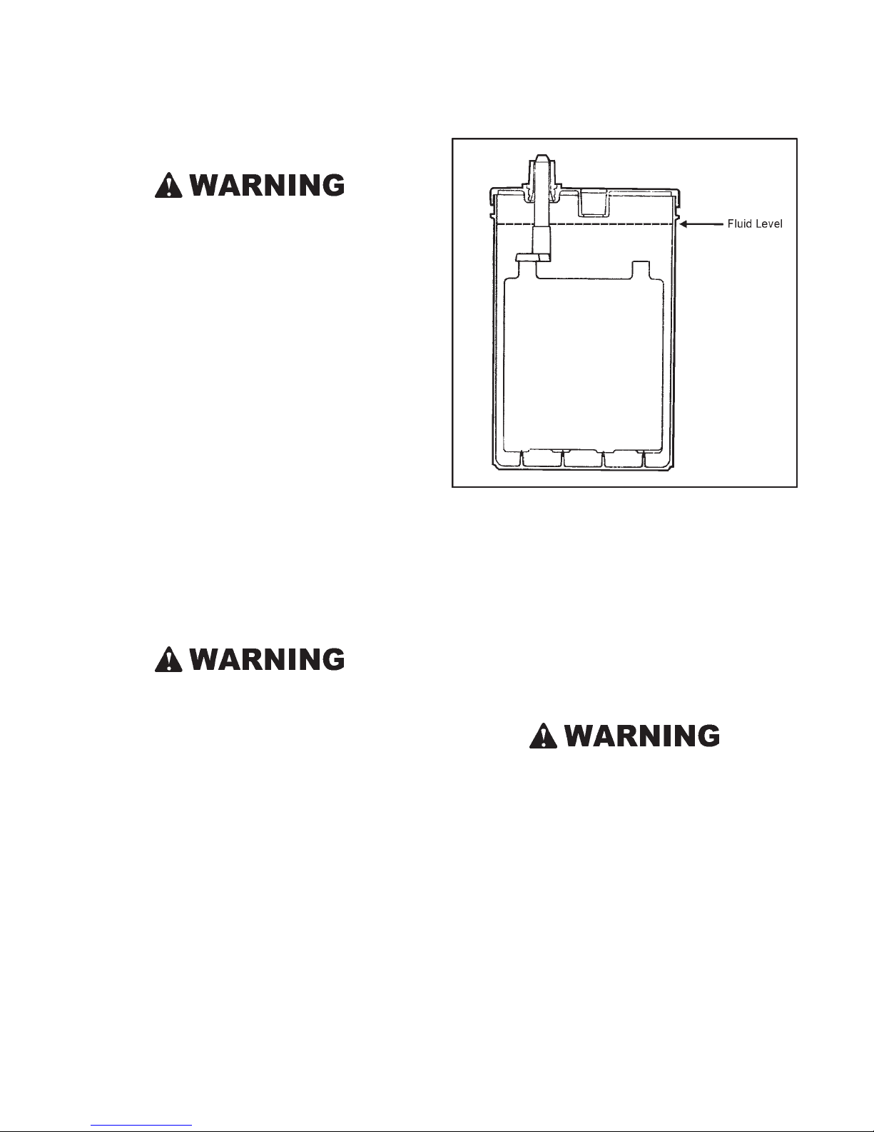
SECTION 7
MAINTENANCE INFORMATION
7.1 ELECTRICAL SYSTEM
Detailed information on standard workshop and safety
procedures and general installation practices is not included here. ODG assumes no responsibility or liability for PERSONAL INJURY or VEHICLE DAMAGE
which results fr om any procedure performed, including
those procedur es outlined her e. Before performing any
procedure, an individual must have determined to his/
her satisfaction that personal injury or vehicle damage
will not result fr om the pr ocedure, working envir onment
or tools selected.
7.1.1 General
To prevent damage to the electrical system:
• Never weld on the vehicle without first disconnecting
both positive and negative battery cables. Make sure the
part you are welding is properly grounded.
• Connect battery booster cables properly , positive to positive and negative to negative. Connect negative cable
last, disconnect first.
• Connect switch terminals properly , especially the ground
wire.
7.1.2 Battery - 613-101
Battery fluid contains sulphuric acid. If battery fluid
comes in contact with skin or eyes, flush thoroughly with
water. If swallowed, call physician or poison control
centre immediately. KEEP AWAY FROM CHILDREN.
Serious personal injury can occur . Always wear r ubber
gloves and safety glasses when servicing the battery.
Batteries can explode and cause serious personal injury if exposed to flame or sparks. Never smoke while
servicing the battery.
All models are equipped with a 12 volt, wet cell type battery.
The battery is located in the engine compartment, on the left
side of the engine.
Checking Fluid Level
Figure 7-1. Battery Fluid Level
Charging the Battery
If the battery loses its electrical charge, remove the battery
from the Centaur and recharge it with a 12 volt battery charger
at the rate of 10-12 amps maximum. The battery should remain on charge until the specific gravity reaches 1.265 on a
hydrometer. Re-install the battery in the vehicle and try to
start the engine. If the battery fails to perform properly , have
it tested by a battery service dealer . Replace a defective battery with Part No. 613-101.
Ventilate area when charging. Keep away from spark,
heat, cigarettes or open flame.
Cleaning the Battery Terminals and Cable Connections
Clean the battery terminals and cable connections every 100
hours. Remove the black NEGATIVE (-) cables first. Make
sure you reconnect the NEGATIVE (-) cables to the NEGATIVE (-) post and the red POSITIVE (+) cables to the POSITIVE (+) posts. Damage to the electrical system will occur if
the cables are reversed.
Check the fluid level every 50 hours of operation. Remove
the vents and make sure each cell is filled to the fluid level as
shown in Figure 7-1. If the fluid has dropped below the fill
well, add distilled water until the cell is filled to correct level.
DO NOT OVERFILL.
Cleaning the Battery
Clean the top of the battery every 300 hours with a mixture of
baking soda and water. Before cleaning the battery, remove
it from the vehicle and make sure the vents are in place. Soak
19
Page 28
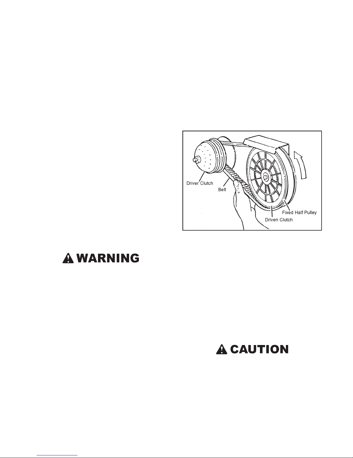
SECTION 7
MAINTENANCE INFORMATION
a cloth in the soda/water mixture and scrub the top of the
battery. After the foaming has stopped, flush with clean water and dry with a clean cloth.
7.1.3 ELECTRICAL SYSTEM FUSES
The Centaur is equipped with push-in type automotive fuses.
The fuses protect the electrical circuits of the vehicle. They
are located in the fuse block, under the dash. Replace any
blown fuses. Return your vehicle to a Centaur dealer for inspection of the electrical circuit if a fuse blows repeatedly.
7.1.4 SPARK PLUGS (GAS ENGINE)
Remove and inspect the spark plugs after every 150 hours of
operation. Clean the plugs and reset the gap as detailed in the
engine owner’s manual.
Replace the spark plugs if the electrodes are corroded or damaged or if the insulator is cracked. Use the correct plug for
the engine as detailed in the engine owner’s manual.
Re-install the spark plugs carefully, taking care to start the
threads properly . Torque the plugs to 10 - 15 ft. lbs (14 to 20
N·m). Do not over tighten.
7.2 DRIVE SYSTEM & TIRES
whenever there is a noticeable reduction in clutch performance. Replace the belt with Part No. 610-119 for Centaur 31
Gas or DT and Part No. 610-119SA for Centaur 34 Gas and
DT when:
• the top width of the belt has worn to 1-1/16" (27mm)
• cracks, fraying or shredding is apparent
• it becomes contaminated with oil or some other fluid
To Remove the Drive Belt:
Figure 7-2. Removing the drive belt
1. Make sure ignition is turned off.
Do not attempt to adjust, repair or replace the drive
belt, clutches or any moving part while the engine is
running. Before servicing the vehicle, disconnect the
battery to prevent accidentally starting the engine.
Keep the engine cover and clutch guard securely in place
when the engine is running. Severe injury can result if
the drive belt, clutch components or other moving parts
come loose.
If engine compartment inspection is necessary while the
engine is running, use EXTREME CAUTION! Keep engine RPM low . A void standing directly in line with moving components. Use a mirror to view the components.
7.2.1 DRIVE BELT
The drive belt transmits power from the driver clutch (on the
engine) to the driven clutch (on the transmission). These components are located on the left side of the engine compartment.
Check the drive belt after every 25 hours of operation, or
2. Remove the engine cover.
3. Place the transmission in N (neutral).
4. Ease the belt over the fixed half pulley of the driven clutch
starting from the bottom of the clutch, while turning the
clutch counterclockwise until the belt is off (Figure 7-2).
5. Remove the belt from the driver clutch.
To Install the Drive Belt:
If this procedure is not car ried out as described, the edge
of the fixed face may cut or damage the drive belt.
1. Position the belt around the driver clutch first.
2. Ease the belt over the edge of the fixed face on the driven
clutch and at the same time, turn the inside, moveable
face clockwise.
20
Page 29
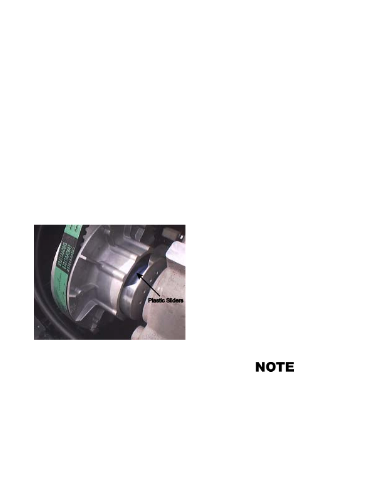
SECTION 7
MAINTENANCE INFORMATION
Drive Belt alignment and tension are pre-set at the factory
and are not adjustable. They are critical for proper operation
of the drive system. Return the vehicle to a CENT AUR dealer
if rapid belt wear occurs.
7.2.2 CLUTCH MAINTENANCE
Disassembly and repair of the driver and driven clutch requires special tools. Return the vehicle to a CENT AUR dealer
if the clutch units need servicing. The following indicates that
clutch service is required:
• a drop in vehicle performance
• the clutch does not shift smoothly
• the clutch sticks during vehicle operation
• the drive belt wears rapidly
• the vehicle vibrates severely during operation
• the vehicle does not accelerate when the engine speed is
increased with the transmission in gear
• transmission will not shift smoothly into gear at engine
idle
7.2.3 DRIVE CHAINS
Roller chain “stretch” results from wear to the chain pins and
bushings because of the loss of lubricant.
To prevent sprocket damage and unnecessary breakdowns,
replace the chains when:
• the chain tensioner can no longer take up the chain slack.
• the chain is seized due to rust and lack of lubrication.
• the chain climbs the sprocket teeth, especially noticeable
when turning.
To Remove the Drive Chains:
1. Place the gearshift in the neutral position.
2. Remove the floor pans.
3. Remove the chain tensioner torsion springs.
4. Roll the vehicle until the connecting link on one of the
chains is visible.
5. Remove the cotter pins from the connecting link. Remove the outside plate and tap out the connecting link.
Figure 7-3. Location of the Sliders
Clutch Inspection
Lubrication of the clutch parts is not required. Do not lubricate the driven clutch.
Inspect the plastic sliders every 50 hours. The plastic sliders
are mounted in the driven clutch moveable pulley . (Figure 7-
3). When the clutch shifts, the cam moves on the nylon sliders.
Replace the plastic sliders before there is aluminum to
aluminum contact between the cam and the movable pulley.
Driven clutch disassembly is required to replace the nylon
sliders properly. Return the vehicle to a CENTAUR dealer
for service.
6. Remove the chain from the vehicle.
7. Repeat steps 3 to 6 until all drive chains are removed.
To Install the Drive Chains:
1. Feed the chain around each sprocket and clamp the free
end with a modified vice grip (ODG part # 658-38). Figure 7-4.
2. Install the connecting link (from the outside in) and cotter pins, orienting and bending the cotter pins as shown
in Figure 7-5.
Use a pair of modified 10R Vice Grips to hold the ends
of the chain together while inserting the connecting link.
Some drive chains have no slack, and replacement of
the connecting link is difficult without this tool. Modified Vice Grips can be ordered from your CENTAUR
dealer (Part No. 658-38) or refer to Appendix 1 for
modification information.
21
Page 30
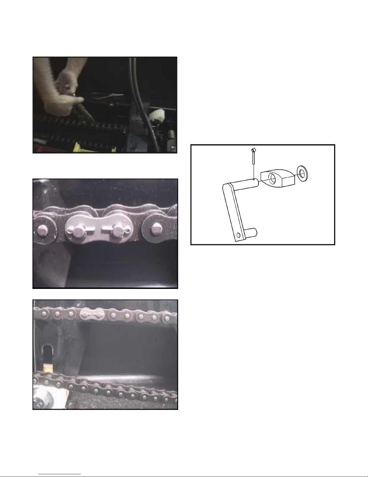
MAINTENANCE INFORMATION
Figure 7-4. Holding chain together to
insert connecting link
SECTION 7
4. Repeat steps 1 to 3 until all chains are replaced.
7.2.4 TO REPLACE A SLIDER BLOCK
1. Remove the floor pans.
2. Pull up on the tensioner arm until slider block is not contacting chain.
3. Remove the cotter pin, washer and slider block from the
tensioner arm. Figure 7-7.
Figure 7-5. Chain connection link components.
Figure 7-6. Installing the connecting link.
3. Replace the outside plate and cotter pins. Always use
new cotter pins. Bend the pins towards the inside of the
loop of chain.
Figure 7-7. Chain tensioner components.
4. Re-install new slider block, washer and cotter pin.
5. Replace the floor pans.
7.2.5 TIRE REPAIR AND REPLACEMENT
Repair a flat tire by removing the tire completely from the
rim. Proper tire changing equipment is necessary to remove
and remount the tire. Apply a radial tire patch on the inside
of the tire over the puncture or hole.
Remount the tire on the rim using ONLY WATER as a bead
lubricant. Spoon the tire onto the rim to prevent tire bead area
damage. THE TIRE MA Y EXPLODE IF OVER-INFLATED.
Place the tire and rim assembly in a protective cage to inflate
and to seat the beads. Never inflate over 32 psi (220 kPa) to
seat the bead. Once both beads are seated, deflate to 3.5 psi
(24 kPa), 5 psi (34.5 kPa) maximum operating pressure. A
special, low pressure tire gauge (Part No. 619-10) is available from your CENTAUR dealer.
Replace badly worn or damaged tires with original equipment Goodyear tires. Consult your CENTAUR dealer if in
doubt. Any other tires (size, type or tread pattern), will af fect
the skid steering characteristics of the vehicle.
22
Page 31
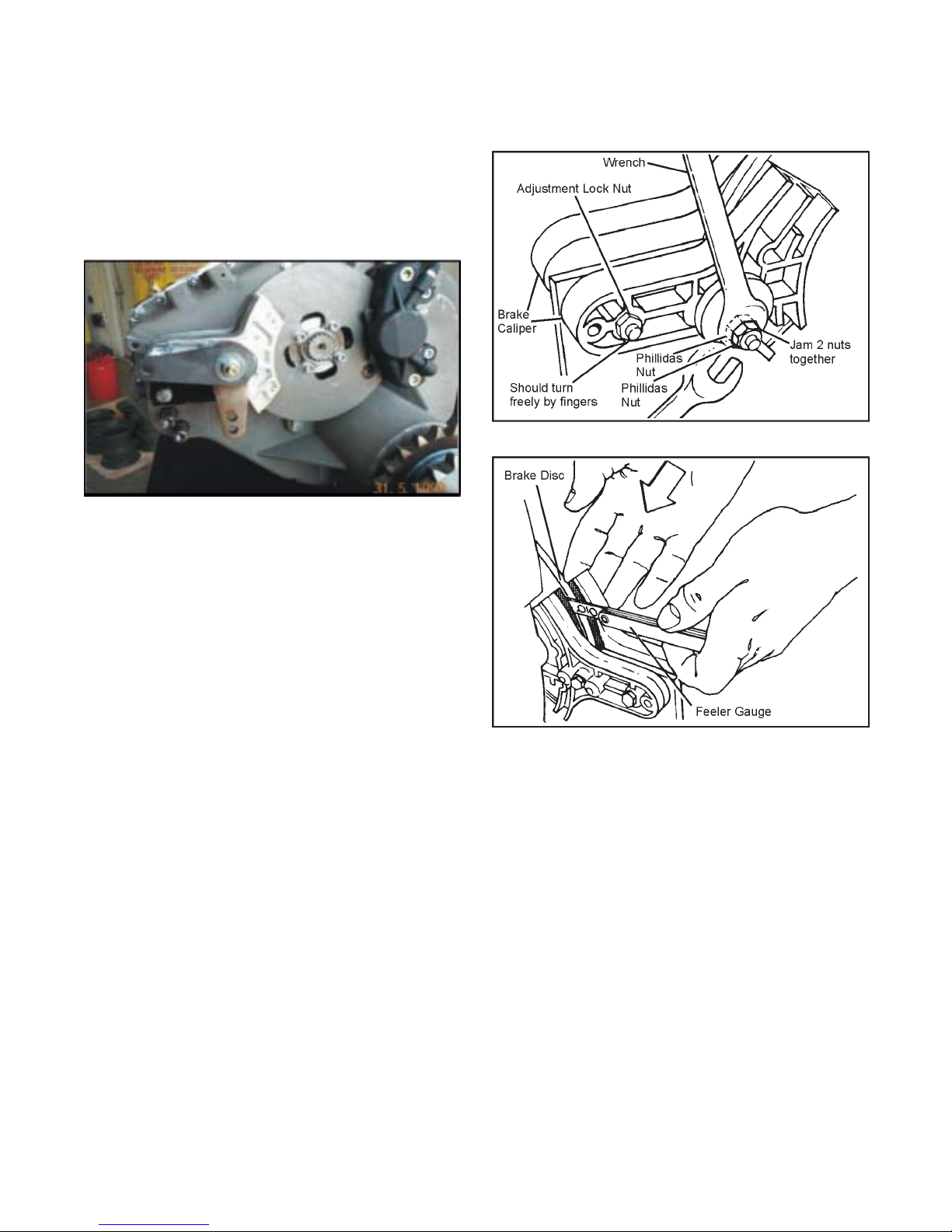
SECTION 7
MAINTENANCE INFORMATION
7.3 MECHANICAL PARKING/EMERGENCY BRAKE
7.3.1 GENERAL
Periodic inspection and adjustment of the parking/emergency
brake system is required to maintain performance.
Figure 7-11. Mechanical parking/emergency brake
Figure 7-12. Tightening the lock nut.
7.3.2 BRAKE CALIPER ADJUSTMENT
With the engine cover and transmission cover removed, inspect the mechanical brake caliper assembly.
Adjust the calipers when:
• the brake adjustment nuts are tightened all the way but
the parking brake cannot be firmly engaged using the
parking brake lever, or
• the total clearance between the brake pads and the brake
disc exceeds .010".
To adjust the brake caliper:
1. Tighten the lock nut with a 1/2" open end wrench, no
wider than the thickness of the lock nut (Figure 7-12).
As the lock nut is tightened, measure the clearance between the brake disc and pad as shown in Figure 7-13,
using a .010" feeler gauge. .010" is the correct clearance
between the left brake pad and the brake disc when the
right pad is pressed against the disc.
2. Use another 1/2" open wrench to tighten the outer lock
nut to the inner one.
3. Tighten the adjustment lock nut with a 1/2" wrench so it
is snug but the bolt can still be turned freely with fingers.
Figure 7-13. Brake pad wear, mechanical brakes.
7.3.3 BRAKE PAD REPLACEMENT
During the inspection of the brake pads, if they are:
• worn to 3 mm (1/8") thickness as shown in Figure 7-14;
• glazed and brake efficiency is affected; or
• contaminated with lubricant and brake performance is
affected;
they are no longer serviceable and must be replaced.
To replace the brake pads:
Use an electric drill and 1/4" drill bit to remove the heads of
the rivets holding the old pads to the calipers. Clear the
remainder of the rivets from the calipers and install 100-56
brake pad set (2 pads) using 8 of 120-09 rivets and a pop
riveting tool to fasten the pad in place. A CENTAUR dealer
will replace brake pads for you.
23
Page 32
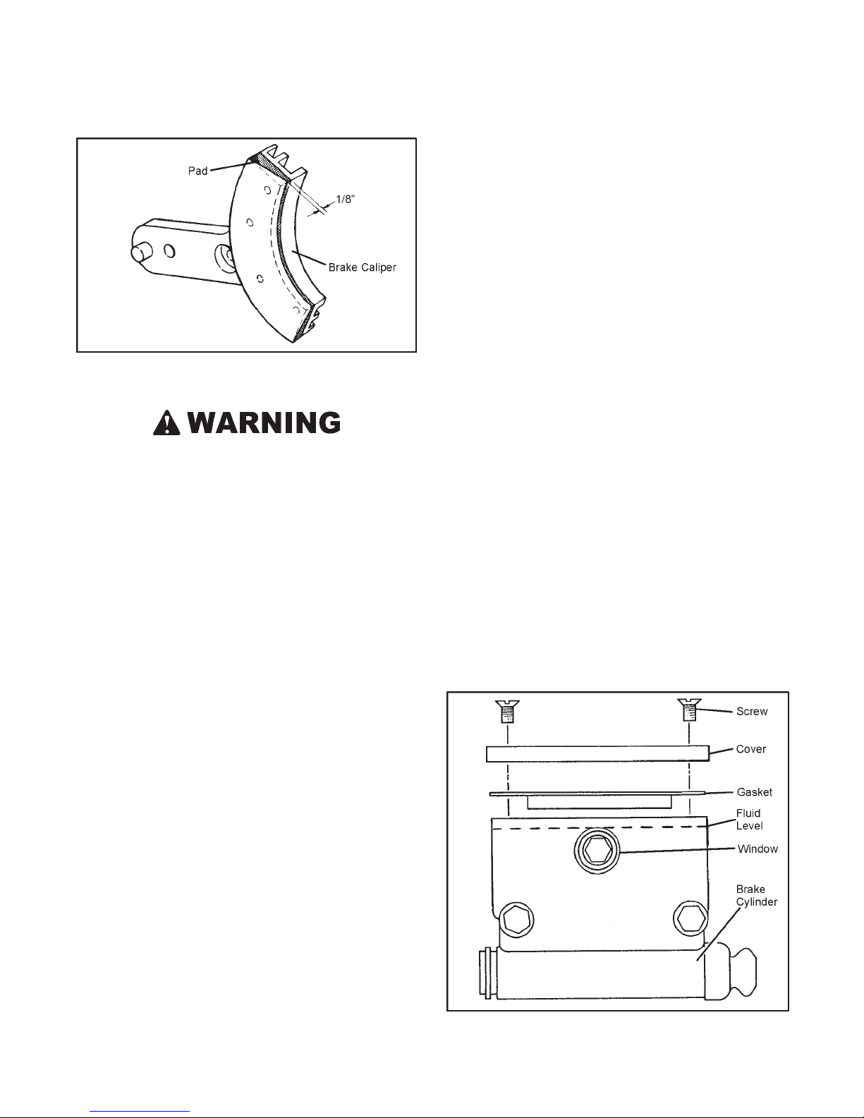
SECTION 7
MAINTENANCE INFORMATION
8. Start up and drive the vehicle for 10 minutes. Stop the
engine and check that the parking brake caliper has not
been dragging. A strong ‘brake material’ smell and a very
hot brake disk would indicate that the parking brake
caliper is adjusted too tight. Readjust if necessary.
7.4 HYDRAULIC BRAKE
7.4.1 GENERAL
Although the hydraulic brake system is self adjusting, the
following require periodic attention:
Figure 7-14. Measuring the distance between the brake disc
and brake pad.
The use of an improperly adjusted parking/emergency
brake is a serious safety hazard, and could lead to vehicle damage or personal injury.
7.3.4 BRAKE CABLE ADJUSTMENT
If, after adjusting the brake caliper, the parking brake lever
still does not firmly apply the parking brake, then brake cable
adjustment is required.
To adjust the brake cable:
1. Adjust the brake caliper first as described above.
2. The cable is adjusted by repositioning the parking brake
lever assembly in it’s slotted mounting holes. Loosen the
mounting bolts and reposition the assembly such that the
cable has just about engaged the parking brake cam.
7.4.2 BRAKE FLUID LEVEL
After every 50 hours of operation, check the brake fluid level
through the side mounted view window in the master cylinder (Figure 7-15). The fluid level must be above the top of
the view window.
If the brake fluid is below this level:
1. Thoroughly clean the master cylinder cover and surrounding area.
2. Remove the two screws, lift off the cover and the gasket.
3. Add only fresh clean SILICONE - DOT 5 BRAKE
FLUID (Part No. 126-19) to the correct level.
4. Replace the cover on the master cylinder, making sure
the rubber gasket is properly seated before tightening the
cover screws.
3. Re-tighten the mounting bolts.
4. Check that the gap between the parking brake caliper
and the brake disk remains at .010".
5. Activate the parking brake lever several times and recheck
the gap.
6. Reposition the parking brake lever assembly if necessary.
7. Start up and drive the vehicle carefully and ensure that
the parking brake will bring the vehicle to a stop when
coasting. Repeat several times, then check the gap between brake pad and the disk and readjust if necessary.
Figure 7-15. Hydraulic brake cylinder and fluid level.
24
Page 33
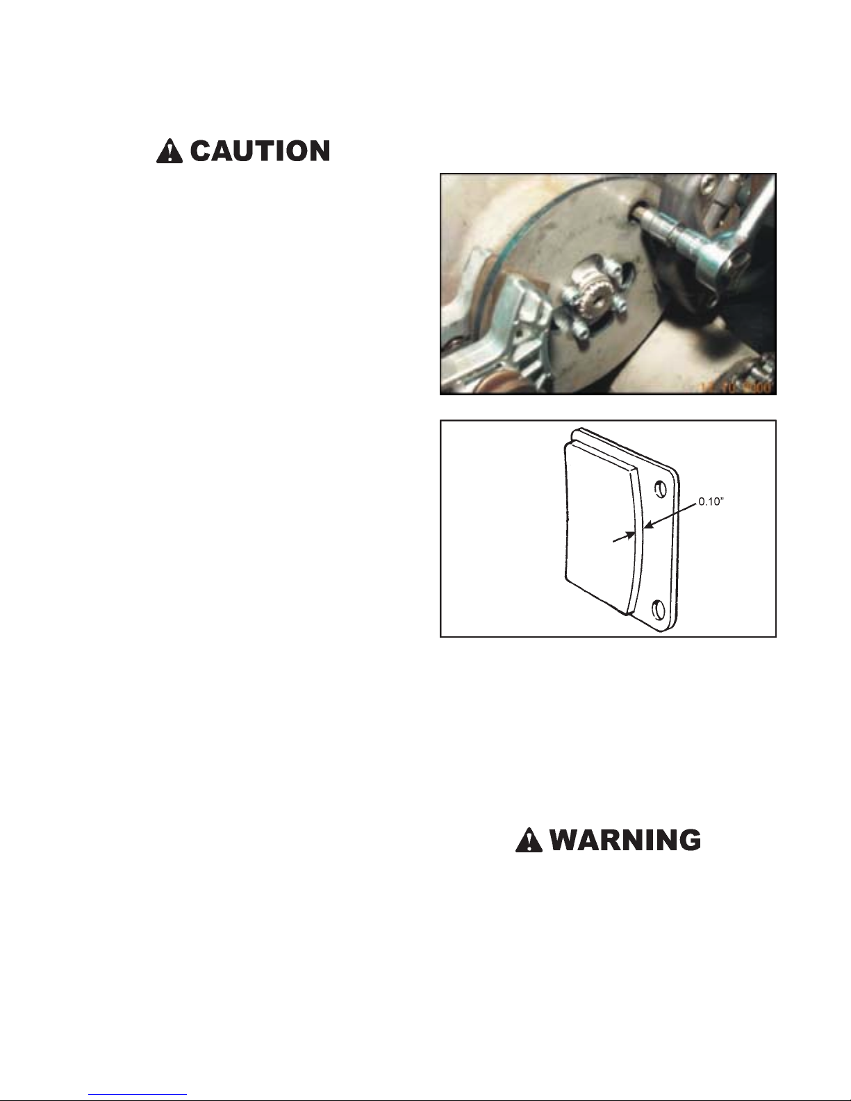
SECTION 7
MAINTENANCE INFORMATION
Do not overfill the brake master cylinders. Fluid level
must be at the top of the view window. Overfilling can
cause seal damage.
Use only SILICONE - DOT5 BRAKE FLUID. Other
brake fluid may not be compatible with brake components and operating temperatures. Use of other fluids
will void the warranty and can cause failure of the brake
system/components.
7.4.3 CHANGING BRAKE FLUID
The inherent stability of Silicone DOT 5 Brake Fluid reduces
the need for frequent brake fluid replacement. Inspect the fluid
for degradation (discolouration or particles) during normal
fluid level inspections. If discolouration has occurred, the
brake fluid system should be drained, flushed and re-filled
with fresh brake fluid. If particles are evident in the fluid,
drain the system, overhaul the master cylinder and the brake
caliper before flushing and refilling. A CENT AUR dealer will
perform these operations for you.
(or equivalent) removable compound on the threads of the
SHCS mounting bolts and tighten securely.
Figure 7-16. Hydraulic brake assembly
7.4.4 HYDRAULIC BRAKE PAD INSPECTION
Inspect the brake pads after every 50 hours of operation. W orn,
glazed or contaminated brake pads affect the efficiency of
the brake system.
Brake Pad Inspection Procedure
With the engine cover removed, the hydraulic brake caliper
is visible. The caliper has 2 brake pads which are secured by
cotter pins (Figure 7-16). Inspect both brake pads. Replace
the pads when:
• the brake lining material molded to each metal backing
plate is worn to 0.10" thickness. (Figure 7-17)
• the pads are glazed and brake performance is affected.
• the pads are contaminated with lubricant, and brake performance is affected.
To replace the brake pads:
Remove both cotter pins from the brake caliper . Remove the
brake caliper from the transmission using a hex driver to remove the two SHCS mounting bolts accessible through the
brake disc hole as shown in Figure 7-16. Without disturbing
the connection of the brake line, swing the caliper away from
the brake disc to allow the removal of the brake pads. Install
the brake pads into the caliper assembly . Insert two new cotter pins and bend the ends over to secure the pads in position.
Remount the caliper to the transmission, using #242 Loctite
Figure 7-17. Brake pad wear, hydraulic brakes.
Pump the brake pedal a few times to build up proper pressure
and to locate the pads in the caliper assembly.
7.4.5 ENGINE COOLING & EXHAUST SYSTEM
Engine cooling air is drawn in on the right side of the engine
compartment and expelled on the left side. Keep all ducting
and screening in place.
If the vehicle is equipped with an enclosed cab of any
sort, make sure there is plenty of ventilation to avoid
exposure to exhaust and engine fumes. Engine exhaust
contains carbon monoxide, an odourless, colourless toxic
gas that will cause serious personal injury or death. Inspect the exhaust system periodically for worn or damaged components. Listen for a change in exhaust or
engine noise that may indicate a dangerous exhaust leak.
If a leak is detected, have the exhaust system repaired
immediately before further use.
25
Page 34
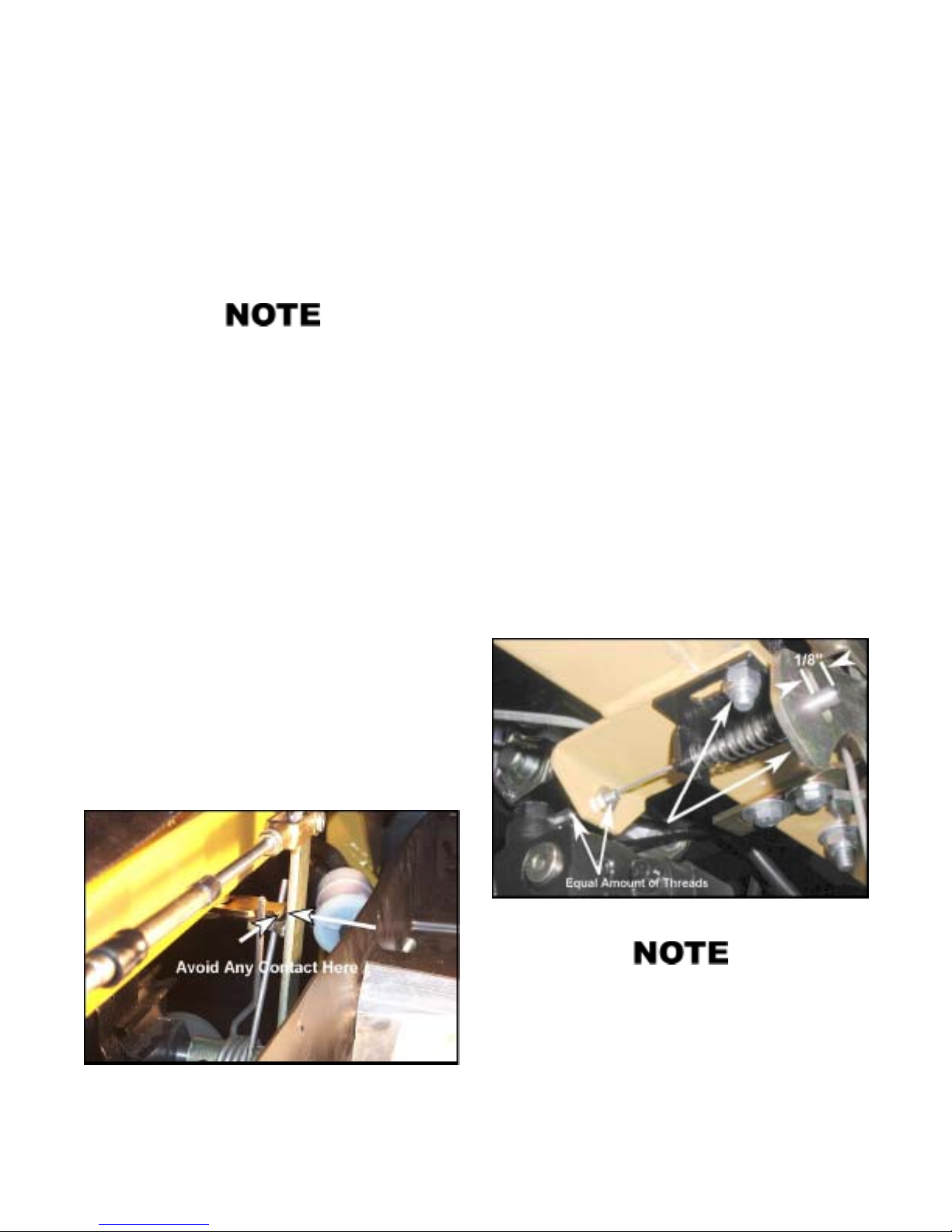
SECTION 7
MAINTENANCE INFORMATION
Check the area around the exhaust system periodically
for accumulated debris, particularly when traveling
through dry vegetation. Failure to inspect and clean
the exhaust system on a regular basis may create a fire
hazard.
DO NOT ALLOW ANYONE TO TOUCH THE EXHAUST COMPONENTS. A SEVERE BURN CAN RESULT.
A complete check over of your CENT AUR vehicle is recommended once a year. This will reduce maintenance
costs over the life of your vehicle and ensure it will function properly during use periods.
7.5 STEERING SYSTEM
7.5.1 STEERING CENTERING ADJUSTMENT
Remove the sheet metal covers covering the hydrostat control arm located under the seat. Lift the vehicle so that all
drive wheels are off the ground.
With the gear shift in neutral, start engine and allow to idle at
1000 rpm. Loosen the steering spring centering plate located
under the ROPS cross tube (under the seat) and adjust to the
left or right until the wheels stop moving.
7.5.2 STEERING WHEEL & LOCK ADJUSTMENT
Adjust the steering cable so that the wheel will be centered
when released. Ensure that the steering wheel has unrestricted
rotation to the stops located at the bottom of the steering wheel
housing. Adjust cable if necessary.
Tighten all nuts and bolts associated with the steering system. Ensure that all cotter pins and hair pins are secured and
free from wear.
Vehicles produced from S/N 0108063 are equipped with a
steering lock. This lock system ensures that the steering wheel
can not be turned until the armrest is in the lowered position.
With the armrest DOWN ensure that the steering lock pin is
not engaged or making contact with the adjustable plate on
the hydrostat unit. Adjust if necessary for sufficient clearance
between the two.
To disconnect or adjust the spring pin end of the cable, remove or loosen the 2 fasteners securing the bracket to the
welded tab on the upper cross brace assembly . Slide the bracket
until approximately 1/8” protrudes through the locking slide
plate when the armrest is in the upright position (Figure 7-
19).
Tighten the plate to 22 ft.lbs (30 N.m) and ensure that the
centering plate does not hit the steering arm when steering
left or right. The plate should be positioned so there is at least
a 1/8” gap between it and the steering arm ( Figure7-18). Tur n
the steering wheel left and release. Turn the steering wheel
right and release. The steering wheel should return to center
each time. Once centred, the wheels should not rotate.
Figure 7-18. Position of steering spring plate.
Figure 7-19. Adjusting the spring pin end of the cable.
Generally, when the cable is fastened at the bracket on
the upper cross brace assembly, if it is installed with an
equal amount of threads on either side of the welded
tab, the cable will be properly set. The bracket need only
then be slid within the slots to achieve the 1/8” measurement required through the locking plate when the
armrest is in the up position (Figure 7-20).
26
Page 35
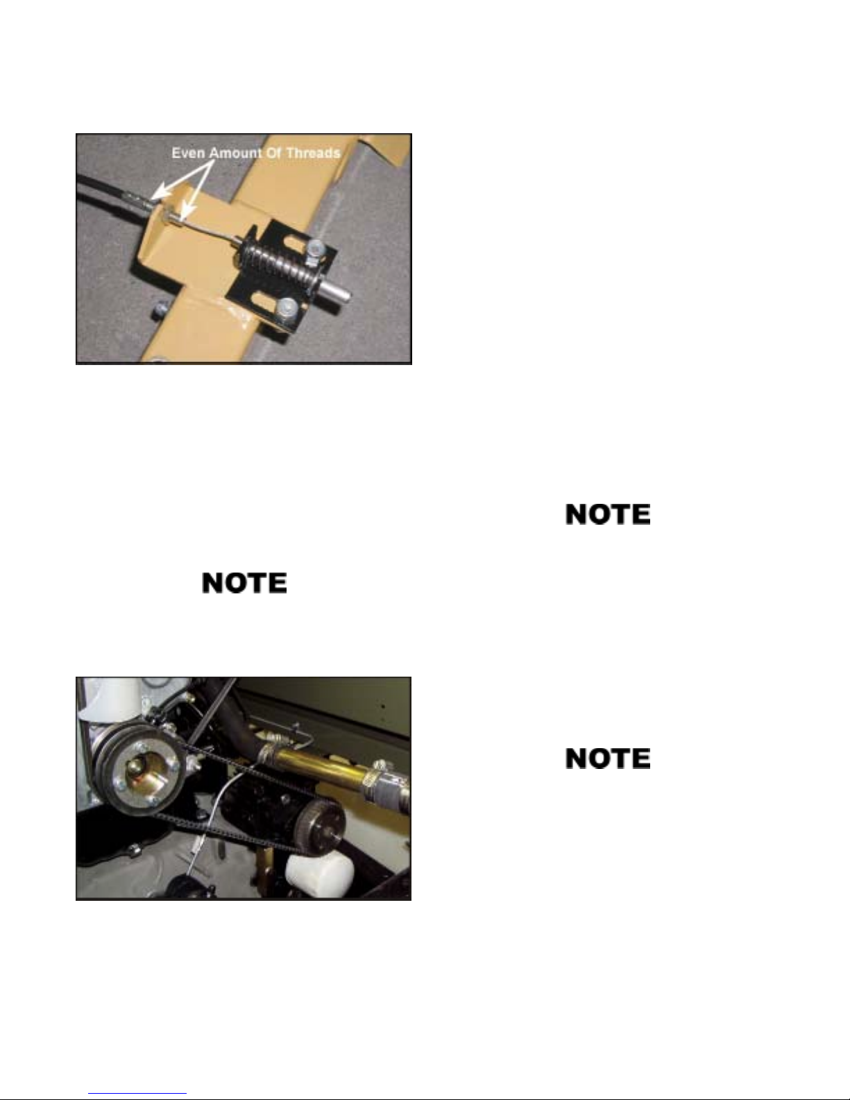
MAINTENANCE INFORMATION
Figure 7-20. Positioning of cable at bracket.
SECTION 7
7.6 SHIFTING SYSTEM
7.6.1 SHIFT CABLE ADJUSTMENT
1. Locate the shift rods at the rear of the transmission on
the passengers side.
2. Shift gear box into neutral, ensuring that the shift rods
are aligned.
3. At the shift box, locate the cables where they are fastened at the entry point of the shift box assembly.
4. Remove the shift gate on the shift box and check to make
sure that the shift blocks are aligned with the shift yoke
assembly when in the neutral position.
7.5.3 HYDROSTATIC TRANSMISSION DRIVE BELT
Loosen the two bolts securing the hydrostat against the vehicle transmission. Rotate the hydrostat towards the engine to
loosen the drive belt. Position a new belt over the engine
pulley and then the hydrostat drive pulley . Rotate the hydrostat to tension the belt so that 6 lbs. of force (2.7 kg or 27N)
causes a deflection of .21" (5.3 mm) at a point midway between pulleys. Torque bolts to 20 lb. ft. (N.m).
On Gas (31 HP only), the lower rad hose is positioned
above the hydrostat belt (Figure 7-21). On 34 DT, 34
Gas and 31 DT, the lower rad hose is positioned between the belt.
5. To adjust the shift cables, the shifting yokes threaded to
the end of the push/pull shift cables must be threaded
further onto the cable or else threaded out further. This is
most easily done by loosening off the nuts from the outside of the shift box and adjusting as needed.
You may need to rotate the clutch to allow the shifting
mechanism within the transmission to permit the lever
to move.
6. Install the shift gate temporarily and shift the gear lever
into low gear. The gear lever should not be making any
contact with the gate plate. There should be at least a
3/8” clearance between lever and gate.
7. For more detailed adjustment procedures, refer to the
Centaur Service Manual, available from your Centaur
dealer or else take the vehicle to an authorized Centaur
dealer for adjustment.
If your vehicle is equipped with micro switches for the
neutral safety and back up alarm, you may need to reposition these in their slotted mounts so they are not
activated when the shifting lever is in neutral position.
Figure 7-21. Positioning of the lower rad hose for gas (31 HP
models only).
7.6.2 THROTTLE CABLE ADJUSTMENT
With the engine stopped, push accelerator to the floor plate
and secure. At the engine check that the throttle arm is fully
open. Adjust throttle arm if necessary.
Operate accelerator a few times then recheck the throttle arm
position. Ensure that all fasteners associated with the throttle
cable are secure.
27
Page 36

SECTION 7
MAINTENANCE INFORMATION
CHECK COOLANT LEVEL
CHECK FAN BELT TENSION
CHECK FUEL LEVEL
CHECK TIRE INFLATION
CHECK ACCELERA TOR PEDAL OPERA TION
CHECK BRAKE PEDAL OPERATION
CHECK STEERING WHEEL TRAVEL
CHECK ENGINE INTAKE/EXH. FOR OBSTR.
CHECK THAT DRAIN PLUGS ARE IN PLACE
CHECK ENGINE OIL LEVEL
CHECK TRANSMISSION OIL LEVEL
CHANGE ENGINE OIL
CHANGE ENGINE OIL FILTER
CHANGE TRANSMISSION OIL AND FILTER
CHECK, CLEAN/REPLACE AIR FILTER
REPLACE FUEL FILTER
SERVICE DRIVEN CLUTCH
CHECK AXLE BEARING OIL LEVEL
CHANGE AXLE BEARING OIL
REMOVE, CLEAN & LUBE. DRIVE CHAINS *LUBRICATE DRIVE CHAINS EVERY 10 HRS
CHECK BATTERY FLUID LEVEL & CAPS
CLEAN BATTERY TERMINALS & CONNEC.
CLEAN BATTERY
CLEAN, ADJUST/REPLACE SPARK PLUGS
CHECK THE DRIVE BELT
CHECK PLASTIC SLIDERS - DRIVEN CLUTCH
CHECK SLIDERS - CHAIN TAKE-UP SYSTEM
INSPECT MECH. BRAKE PADS
ADJUST PARKING BRAKE
ADJUST PARKING BRAKE CABLE
CHECK HYD. BRAKE FLUID LEVEL/COND.
INSPECT HYDRAULIC BRAKE PADS
CHECK/ADJUST STEERING CENTERING
CHECK HYDROSTATIC TRANS. DRIVE BELT
TENSION
CHECK FUEL TANK CONNECTIONS/LINES
INSPECT WIRING HARNESS
BEFORE
EACH
USE
AFTER INITIAL
10hrs. 25hrs. 25hrs. 50hrs. 100hrs. 150hrs. 300hrs.
X
X
X 2.2
X 2.2
X 2.2
X 2.2
X
X 2.2
X 5.6
X 6.1.1
X 6.2.1
X X 6.1.3
X X 6.3.3
X X 6.2.2
X X 6.3.2
X X 6.4.4
X
X 7.2.1
X X 7.2.4
X 7.3.3
EVERY
X 6.3.1
X 6.4.3
X 6.4.4
X 6.4.2
X 7.1.2
X 7.1.2
X 7.1.2
X 7.1.4
X 7.2.2
X 7.3.2
X 7.3.4
X 7.4.2
X 7.4.4
X 7.5.1
X 7.5.3
X
X
SECTION
REF.
The intervals shown on the schedule are based on average operating conditions. Vehicles which are subject to
more severe use, wet or dusty conditions, will require more frequent servicing. Use only Centaur replacement parts
to ensure safe operation of the vehicle to comply with the warranty coverage.
We strongly recommend that a Centaur Dealer perform a complete check-over of your vehicle af ter the initial
25 hours of operation, then once each year. This will reduce maintenance cost s over the life of your vehicle.
28
Page 37

SECTION 8
TROUBLE SHOOTING
MALFUNCTION PROBABLE CAUSE CORRECTIVE ACTION
(SYMPTOM)
Electric starter inoperative 1. Loose electrical connections 1. Clean and re-tighten electrical
connections
2. Battery charge low or dead 2. Recharge battery or replace as
necessary
3. Faulty starter motor 3. Return the vehicle to a
CENTAUR dealer for servicing
4. Faulty ignition switch 4. Replace ignition switch
Engine turns over but will not 1. Engine is cold and choke is not 1. Pull out the choke and try to start
start pulled out (gas engine) again
2. Fuel tank is empty 2. Refill tank
3. Blocked fuel or air filter 3. Remove obstruction or replace
filter as necessary
4. Spark plugs defective or fouled 4. Clean and re-gap or replace
(gas engine)
5. Ignition system inoperative 5. Have unit serviced by a properly
(gas engine) trained and equipped mechanic
6. Insufficient compression 6. Take the vehicle to a factory authorized engine repair outlet
7. Gas engine fuel delivery system 7. Check that electric fuel pump is
is faulty operating. Make sure fuel shut
off solenoid is activated to allow
fuel into carburetor.
Engine will not run 1. Refer to engine manual
Vehicle will not move and/or turn 1. Transmission in neutral or not 1. Place gear shift properly in gear
properly engaged in gear
2. Drive belt worn (see Section 7.2.1) 2. Replace belt if worn excessively
3. Clutch not engaging 3. Return the vehicle to a CENTAUR
dealer for servicing
4. Transmission failure 4. Same as 3. above
5. Steering wheel lockout is engaged. 5. Lower arm rest and/or readjust/
replace lockout cable.
6. Hydrostat belt 6. Replace belt
7. Hydrostat faulty 7. Return to a CENTAUR dealer for
servicing.
Severe vibration when vehicle 1. Loose engine mounts 1. Take vehicle to a CENTAUR
is operated dealer for service.
2. Driver or driven clutch or engine 2. Same as above.
defective
3. Wheel rim bent 3. Replace.
4. Worn or damaged drive belt 4. Replace. Clutch service may be
required.
29
Page 38

SECTION 8
TROUBLE SHOOTING
MALFUNCTION PROBABLE CAUSE CORRECTIVE ACTION
(SYMPTOM)
Water leaks into lower body 1. Leak has developed at the axle 1. Replace the flange seal.
assembly
2. Lower body is cut or punctured 2. Repair or replace vehicle skid
plate and/or lower body.
3. Drain plugs not in place 3. Secure drain plugs.
Tire leaks air 1. Tire is punctured 1. Remove tire from rim and re-
pair the hole with a radial tire
patch or install a tube in the tire.
2. Tire is not properly seated on bead 2. Deflate tire and carefully push
tire bead off the rim. Clean the
rim bead area to remove dirt
and foreign matter. Re-inflate tire.
3. Position of air leak is not obvious 3. Submerge tire and rim in a water
tank. Air may be escaping through
the rim halves or the valve stem.
Repair as required.
4. Defective valve 4. Replace defective valve.
Hydraulic brakes are spongy, 1. Air in hydraulic system 1. Have a CENTAUR dealer bleed
or there is excessive brake the brake system and add fluid.
pedal travel
2. Leak in system 2. Have a CENTAUR dealer check all
fittings, hoses, calipers and seals
for loose connections or leakage.
Refill as needed.
Brakes ineffective 1. Pads have overheated and glazed 1. Have the pads cleaned by a
CENTAUR dealer or replace.
2. Pads worn beyond 0.10" 2. Replace.
3. Pads are contaminated with 3. Have the pads cleaned by a
lubricant CENTAUR dealer or replace pads.
There is a loud bang when the 1. Drive chains worn/loose 1. Adjust/replace drive chains as revehicle is turned right or left quired.
2. Engine and transmission mounts loose 2. Tighten all mounting points.
30
Page 39
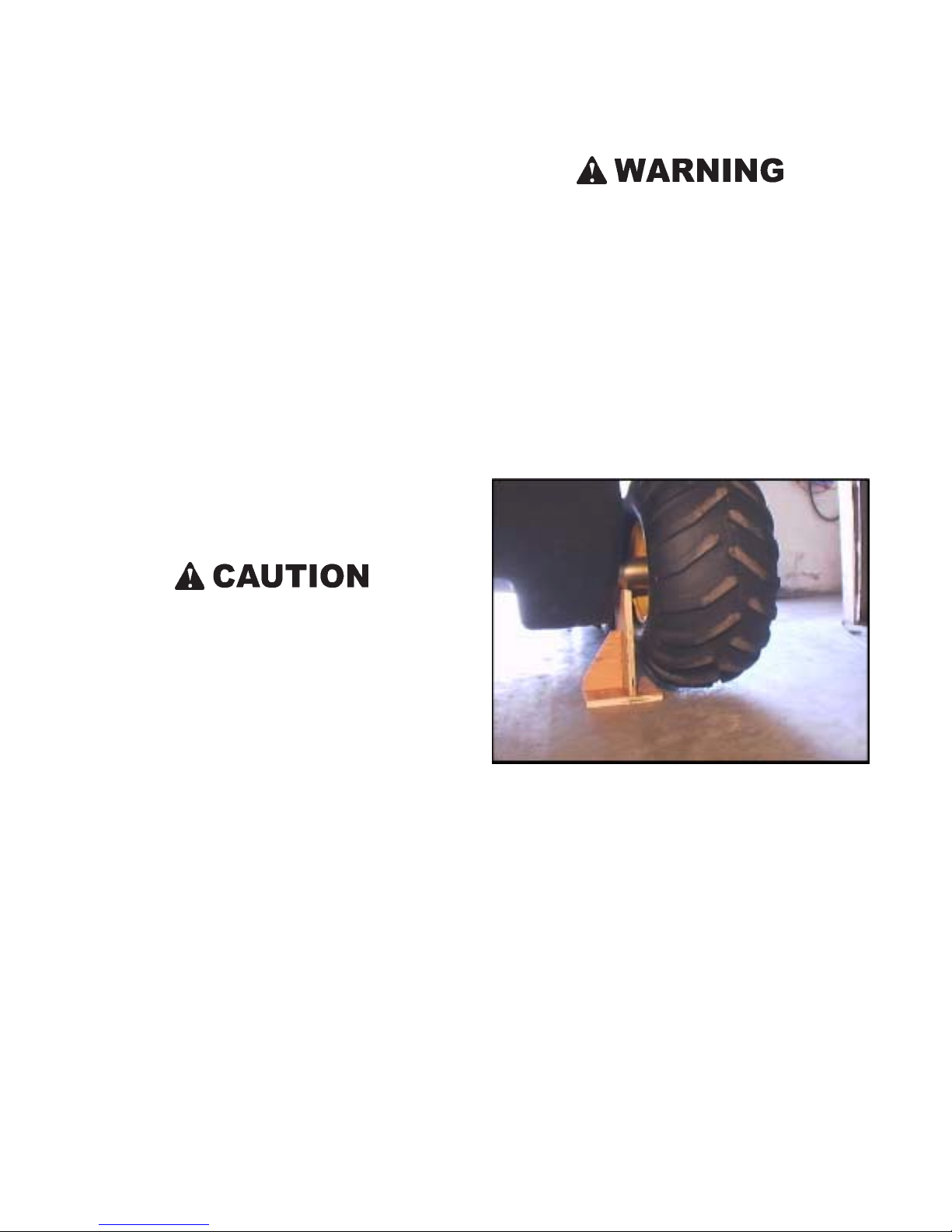
9.1 CLEANING THE VEHICLE
SECTION 9
CLEANING AND STORAGE
Wash the vehicle body with a household detergent and rinse
with water. Flush dirt out of the lower body by using a high
pressure sprayer or garden hose after removing the drain plugs.
After the bottom of the vehicle is dry, lubricate the drive chains
with chain lube. Make sure the drain plugs are replaced.
9.2 STORING THE VEHICLE
When the vehicle is stored for an extended period, the following preparation is required:
Clean the Vehicle
Remove all dirt and water from the vehicle body as directed
above.
Remove the drain plugs if the vehicle is not fully sheltered
from the elements.
Any water accumulation in the vehicle will, over time,
destroy chains and sprockets.
Do not store the battery near flames, sparks or any source
of fire. Batteries can explode if exposed to flames or
sparks, causing serious personal injury.
Recharge the battery monthly.
Protect the Electrical System
Spray the wiring harnesses and all the electrical connections
with a silicone based lubricant (WD40 or equivalent) to prevent corrosion.
Carefully inspect the wiring for loose connections, bare wires
or corrosion. Repair as necessary.
Drain the Fuel System - Gas Models Only
Insert a siphon hose into the gas tank through the filler neck
and drain the fuel. Start the engine and run it until all fuel in
the system is consumed.
OR
Add fuel stabilizer (Part No. 125-85) to the fuel tank and fill
with fresh fuel. Run the engine for a few minutes to allow the
treated fuel to reach the engine.
Prepare the Battery for Storage
Remove the battery from the vehicle. Clean it and charge it
with a battery charger . Coat the battery terminals with a multipurpose grease to prevent corrosion. Store the battery in a
cool dry place.
Figure 9-1. Correct placement of blocks
Raise the Vehicle
Place blocks under the front and rear axle assemblies of the
vehicle to raise the tires off the ground. The blocks must be
placed under the axle tubes to prevent body damage (Figure
9-1).
Preparing the Engine for Storage
Read the engine operator’s manual and carry out all recommended storage procedures.
31
Page 40
SECTION 10
POTENTIAL HAZARDS
POTENTIAL WHAT CAN HAPPEN HOW TO AVOID THE HAZARD
HAZARD
Operating the Centaur
without reading and understanding the Operator’s Manual
Allowing anyone under
age 16 to operate this
vehicle.
Operating or riding as
a passenger in the
Centaur without wearing eye protection and
protective clothing.
Operating the Centaur
after or while consuming alcohol or drugs.
Carrying passengers in
the dump box.
Carrying cargo when
using the Centaur in
water.
The risk of accident is greatly increased if the
operator does not know how to operate the
Centaur properly in different situations and on
different types of terrain.
Children under the age of 16 may not have the
skills, abilities, or judgement needed to operate
the Centaur safely and may be involved in an
accident causing severe injury or death.
Operating or driving without eye protection can
result in an accident and increases your chances
of a severe injury in the event of an accident.
Could seriously affect your judgement, cause you
to react more slowly, and affect your balance and
perception. This could result in an accident.
Riders can fall off and be killed.
Centaur vehicles may sink if they fill with water,
resulting in injury or drowning to driver and passengers.
If the vehicle upsets or swamps, exposure in cold
water significantly reduces the chance of survival.
New or inexperienced operators should read and
understand the Operator’s Manual. They should
then regularly practice the operating techniques
described in this Operator’s Manual.
No one under the age of 16 should be allowed to
operate the Centaur.
W ear an approved safety helmet and eye protection when driving or riding in the vehicle.
Never allow anyone under the influence of alcohol or any other intoxicating substance to drive
or ride in the vehicle.
Never use with drugs or alcohol.
No riders in the dump box.
Be especially cautious when operating a loaded
vehicle (cargo and/or passengers) in water. Observe the capacity limits. Do not enter water if
the vehicle is overloaded.
Use extra caution when operating the Centaur in
cold water.
Operating the Centaur
in water when equipped
with a dump box.
Operating the Centaur
in water without drain
plugs properly installed.
Using the Centaur to
tow anything in the
water other than a
Centaur amphibious
trailer.
Operating the Centaur
in rough water.
Greatly reduces your ability to balance and control the Centaur in the water . Could cause an accident, including capsizing and sinking, resulting
in injury or drowning to driver and passengers.
Will cause the vehicle to fill with water and cause
it to capsize or sink, which could result in injury
or drowning to driver and passengers.
Greatly reduces your ability to balance and control the Centaur in the water. Could cause an accident, including capsizing and sinking, which
could result in injury or drowning to driver and
passengers.
Greatly reduces your ability to balance and control the Centaur in the water. Could cause an
accident, including capsizing and sinking, which
could result in injury or drowning to driver and
passengers.
32
Do not use the Centaur in water when equipped
with a dump box.
Always make sure the drain plugs are properly
installed in the Centaur as described in the Operator’s Manual.
Never tow anything other than a Centaur amphibious trailer when the Centaur is used in water.
Keep cargo low and centered in the trailer, especially if used in water.
Do not attempt to navigate any body of water
with a strong current. A void water operation under windy conditions.
Do not attempt to cross large bodies of water.
Stay close to shore in case of emergency and
you have to leave the water.
Page 41
SECTION 10
POTENTIAL HAZARDS
POTENTIAL WHAT CAN HAPPEN HOW TO AVOID THE HAZARD
HAZARD
Operating or driving the
Centaur in water without the occupants wearing an approved personal flotation device
(PFD).
Operating the Centaur in
water without taking
along a paddle.
Failure of driver and
passengers to adjust positions so that the vehicle is floating level
when operating the
Centaur in water.
Failure to enter the water correctly.
Carrying more than
specified number of
people in a Centaur, either on land or in water.
Overloading the vehicle.
If you lose control of the Centaur in water and it
capsizes and sinks, the driver and passengers may
be injured or drown.
If you run out of gas or have an engine failure the
Centaur will not be able to move under it’s own
power and you may be stranded.
Water may enter the vehicle and cause it to capsize or sink, which could result in injury or drowning to driver and passengers.
You may cause waves, which will enter the
Centaur and cause it to capsize or sink, which
could result in injury or drowning to driver and
passengers.
Greatly reduces ability to balance and control the
Centaur on both land and in the water and could
cause an accident, resulting in injury or death to
driver and passengers.
Heavy loads and high loads decrease the stability of the vehicle and may cause it to roll.
Trying to steer an overloaded vehicle can damage the steering system. Overloading your vehicle can lead to costly damage to steering system,
transmission, drive chains, axles or bearings.
All occupants must wear an approved personal
flotation device (PFD) or life jacket while travelling in water.
Equip the vehicle with a paddle and bailing can.
When using the Centaur in water, adjust the position of cargo and passengers so the vehicle floats
level.
The point of entry should be free of rocks, stumps
and other obstacles. Enter the water from a firm,
gradual slope whenever possible. Be careful not
to submerge the bumper as you enter the water.
Never exceed the load capacity of the Centaur.
Follow the recommended load capacity for your
vehicle listed in Section 1.
Never exceed the load capacity of the Centaur.
Follow the recommended load capacity for your
vehicle listed in Section 1.
Failure to fasten seat
belts.
Failure to unfasten seat
belts when the vehicle
is in water.
Failure to inspect the
Centaur before operating. Failure to properly
maintain the Centaur.
Failure to keep doors
free for unrestricted exit
when operating in water.
If the Centaur overturns, the driver and passengers may be thrown from the vehicle and be seriously injured or killed.
If the Centaur capsizes or sinks the driver and
passengers may be unable to unfasten their seat
belts and may drown.
Increases the possibility of an accident or equipment damage.
If the Centaur capsizes or sinks, the occupants may
be trapped inside and may drown.
Seat belts must be properly adjusted and worn
by all occupants at all times EXCEPT when operating in water.
Do not use seat belts or any passenger restraining device while operating a Centaur in water.
Always inspect your Centaur each time you use
it to make sure it is in safe operating condition.
Always follow the inspection and maintenance
procedures and schedules described in this Operator’s Manual.
Always ensure there is an unrestricted exit when
operating in water.
33
Page 42
SECTION 10
POTENTIAL HAZARDS
POTENTIAL WHAT CAN HAPPEN HOW TO AVOID THE HAZARD
HAZARD
Operating the Centaur
with improper tires or
with improper or uneven tire pressure.
Operating the Centaur
with improper modifications.
Applying brakes suddenly when going
downhill.
Operating Centaur on
public streets, roads or
highways.
Never operate at excessive speeds.
Use of improper tires on the Centaur, or operation of the Centaur with improper or uneven tire
pressure may cause loss of control increasing your
risk of an accident.
Improper installation of accessories or modification of the Centaur may cause changes in handling which in some situations could lead to an
accident.
Sudden braking can cause the vehicle to roll
over forward.
A collision can occur with another vehicle.
Personal injury or vehicle damage may result. Do not drive the vehicle at high speeds over un-
Always use the size and type tires specified in
this Operator’s Manual for this Centaur. Always
maintain proper tire pressure as described in this
Operator’s Manual.
Never modify the Centaur through improper installation or improper use of accessories. All parts
and accessories added to this Centaur should be
genuine Centaur components designed for use on
the Centaur and should be installed and used according to instructions. If you have questions,
consult an authorized Centaur dealer or contact
Ontario Drive & Gear Limited at 1-519-662-4000
Gently apply the brakes to control downward
vehicle speed. Do not jam on the brakes while
travelling downhill.
Never drive on public roads.
familiar or rough terrain.
Never operate at speeds too fast for your skills or
the conditions.
Failure to use extra care
when operating the
Centaur on unfamiliar
terrain.
Failure to use extra care
when operating on
rough, slippery or loose
terrain.
Turning improperly. When turning, the back of the vehicle swings to
Driving on inclines with
a loaded vehicle.
Going downhill improperly.
Personal injury or vehicle damage may result. Do not drive the vehicle at high speeds over un-
Could cause loss of traction or vehicle control,
which could result in an accident, including
an overturn.
the opposite direction of the turn, creating a risk
of hitting persons or objects.
Sharp turns, especially at high speeds or when
heavily loaded, may cause the vehicle to roll over.
Heavy loads and high loads decrease the stability
of the vehicle and may cause it to roll.
Sudden braking can cause the vehicle to roll
over forwards.
familiar or rough terrain.
Do not operate on rough, slippery or loose terrain until you have learned and practised the skills
necessary to control the Centaur on such terrain.
Always take precautions when making turns to
avoid rolling the vehicle or hitting persons or
objects.
Slow the vehicle down before making a turn. Do
not apply the brakes too suddenly.
Use extreme CAUTION when negotiating inclines with a loaded vehicle. Be prepared to shift
occupant weight and load forward or have passengers get out of the vehicle to walk up an incline.
Avoid steep declines when possible. When a steep
decline cannot be avoided, shift occupant weight
to the rear of the vehicle to prevent the vehicle
from rolling over.
34
Page 43
SECTION 10
POTENTIAL HAZARDS
POTENTIAL WHAT CAN HAPPEN HOW TO AVOID THE HAZARD
HAZARD
Improperly crossing
hills or turning on hills.
Side slope operation greatly increases the risk of
rolling the vehicle over sideways.
Prolonged side slope operation may cause engine damage.
Do not drive your vehicle across the side of a
hill.
Observe the engine angle of operation limitations
in Section 5.2.
Stalling or rolling backwards while climbing a
hill.
Improperly operating
over obstacles.
Skidding or sliding. You may lose control of the Centaur. You may
Improperly operating in
reverse.
Could cause loss of control which could lead to
an accident including an overturn.
Personal injury or vehicle damage may result.
also regain traction unexpectedly which may
cause the Centaur to overturn.
You could hit an obstacle or person behind you
resulting in serious injury.
When turning in reverse, steering operation is
opposite to automobiles, similar to backing up a
trailer.
Try to avoid steep hills. Maintain steady speed
when climbing a hill. If you lose all forward
speed:
- keep vehicle pointed up hill
- gently apply the brake
- slowly coast backwards down the hill using
the brake to control the descent
Before operating in a new area, check for obstacles. Never attempt to drive over large obstacles
such as large rocks or fallen trees. When you go
over obstacles always follow proper procedures
as described in this Operator’s Manual.
Learn to safely control skidding or sliding by
practising at slow speeds and on level, smooth
terrain. On extremely slippery surfaces, such as
ice, go slowly and be very cautious in order to
reduce the chance of skidding or sliding out of
control.
Carefully practice backing up and turning in an
open area until you become accustomed to this
procedure. T ake precautions to avoid hitting persons or objects.
Running the engine in a
closed building or confined area.
Adding fuel while the
engine is running or
hot.
Filling outboard motor
fuel tanks while they
are in the Centaur.
Engine exhaust gases contain poisonous carbon
monoxide. Carbon monoxide is odourless, colourless and can cause serious injury or death.
Fuel is extremely flammable and can explode under certain conditions, causing serious injury or
death.
Gasoline is extremely flammable and can explode
if ignited, causing serious injury or death.
Never start or run the engine in a closed building
or confined area.
Do not add fuel while the engine is running or
hot.
Fill outboard motor fuel tanks outside of the vehicle. Wipe up any spilled fuel immediately . Do
not carry or store fuel tanks in a vehicle equipped
with a cab or convertible top unless adequate
ventilation is provided.
35
Page 44
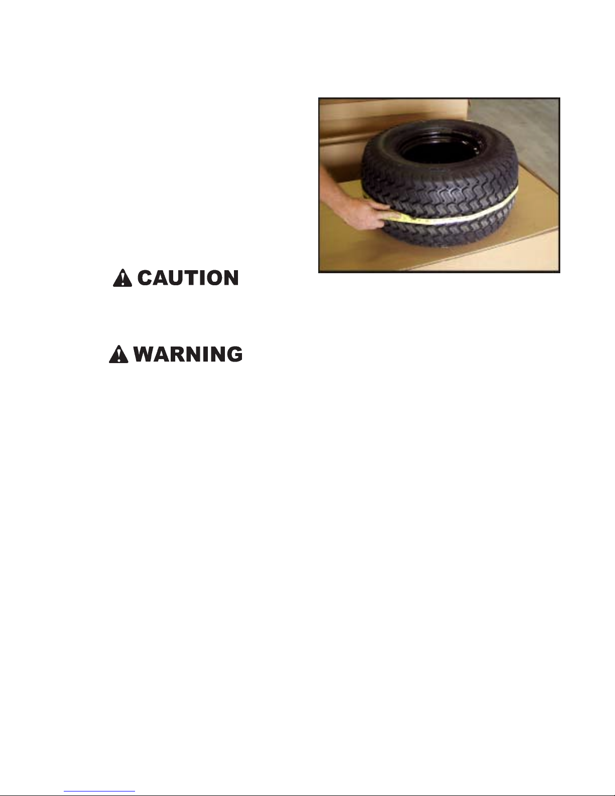
SECTION 11
ACCESSORY INFORMATION
11.1 GENERAL
This section deals with accessories that have been specifically designed for the CENT AUR and can be purchased separately from your dealer. Special operating procedures and
safety precautions must be observed before operating or using certain accessories.
11.2 REAR CARGO TIE DOWN BARS (Part No. 849-
116)
Rear cargo tie down bars are mounted to the rear upper frame.
They provide points to secure your load.
Figure 11-1. Measuring the tire.
Never attempt to raise the vehicle by using the tie down
bars as lifting points.
Never exceed gross vehicle weight. Never exceed the
maximum rear compartment weight for Centaurs.
11.3 ALL SEASON TRACK KIT (Part No. 849-150)
Available in a 15” wide mud and snow application, the rubber track system will allow for ultimate all terrain performance.
The track systems spread the weight of the vehicle over a
larger area than the tires, thereby reducing the ground pressure and allowing the vehicle to stay on top rather than sinking into soft terrain.
11.3.1 Track Installation
1. Tires must be checked for size to ensure that equal size
pairs are installed in each track. If this is not done, chain
windup will happen causing damage to the drive system
components. Tires can be sized this way:
a. With the tires still off the machine, inflate them all
to 10 psi. If the tires were just installed on rims or
were left set under 5 psi, it is very important that
the tires have a chance to sit for at least 24 hours
while pressurized. Re-check the tire pressure and
re-set to 10 psi if required.
b. Measure the circumference of each tire using a suit-
able tape measure, being sure to measure around
the center-line of the tire. Figure 11-1. Write down
the measurement on each tire.
c. Try to put matched tire sizes in each track; i.e. From
the eight tires, pair them off so each two tires in a
pair have a circumference within 1/2" of each other
and then put the smaller of these two toward the
front and the larger one toward the back of each
track. Do the same for all 4 pieces of rubber track.
Two tires that measure the same circumference when at
10 psi, should always be the same circumference when
at equal pressure. Check tire pressure every 10 hours
and adjust so that front and rear tires have equal pressure.
2. If tire sizing is strictly adhered to, all drive chains should
be left connected to the drive train for optimum performance. If you are experiencing frequent drive chain
windup, remove tracks and recheck tires to ensure that
front and rear tire circumference is equal with equal tire
pressure.
3. Release air pressure in the Multi Trac XT tires.
4. Put two deflated tires into the track (Figure 11-2).
5. Manoeuver the assembly into position on two wheel hubs
and secure the wheel nuts (Figure 11-3).
36
Page 45
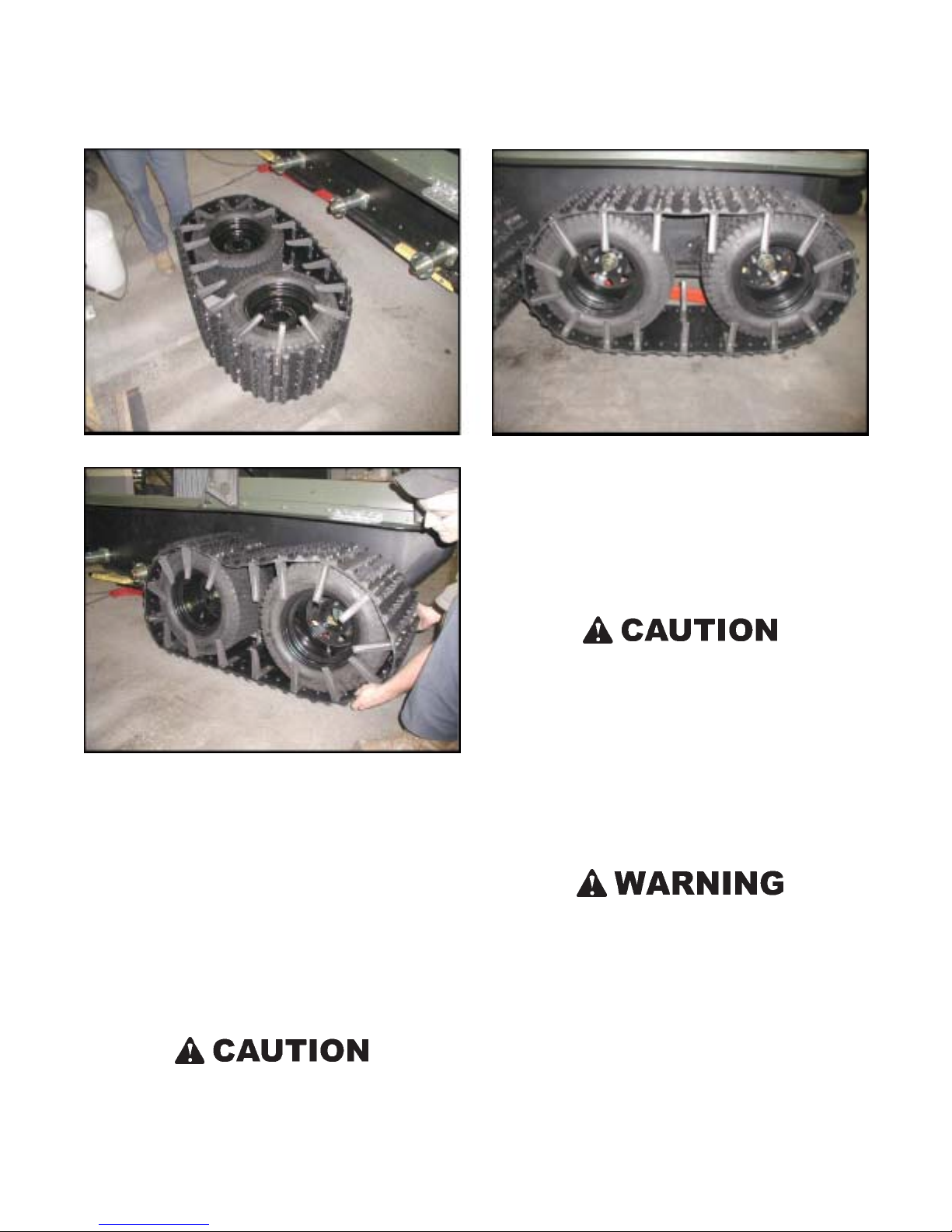
SECTION 11
ACCESSORY INFORMATION
Figure 11-2. Deflated tires into track
Figure 11-3. Positioning on wheel hubes.
6. Re-inflate tires (to between 10 and 20 psi) until tracks
are no longer loose. (But no less then 10 psi tire pressure.) (Figure 11-4).
7. These tires grow fairly dramatically with increased air
pressure:
The circumference of the tire is:
68.5" at 0 psi
70.2" at 5 psi
71.5" at 10 psi
72.4" at 15 psi
74.5" at 20 psi
DO NOT OVER INFLATE! Too much track tension can
damage bearings and axle housings.
Figure 11-4. Re-inflating tires.
11.3.2 Operating Precautions
A Centaur equipped with tracks cannot be used in water or
over frozen bodies of water. Tracked Centaur models have a
reduced capacity on land. Refer to Section 1.4.1 of this manual
for additional information on operating capacities.
CAUTION should be observed when operating in winter conditions and a drop in temperature occurs. Snow
and slush accumulation in the track could freeze, r esulting in damage to the track system. Slush, snow and ice
accumulation should be cleared from the axles and track
periodically to prevent build-up.
CAUTION should be observed when using any track
system on a Centaur . Make sur e the guides and backing
plates are properly secured in each track. Failure to
secure them can result in lower body damage.
EXTREME CAUTION must be observed when using
the track systems on icy surfaces. Steering and braking
effectiveness will be reduced. Reduce speed.
EXTREME CAUTION must be observed when crossing ice-covered water. The vehicle will sink if it breaks
through the ice surface and fills with water. Make sure
drain plugs are securely in place and do not overload
the vehicle. Ice must be thick enough to support the
fully loaded vehicle.
37
Page 46
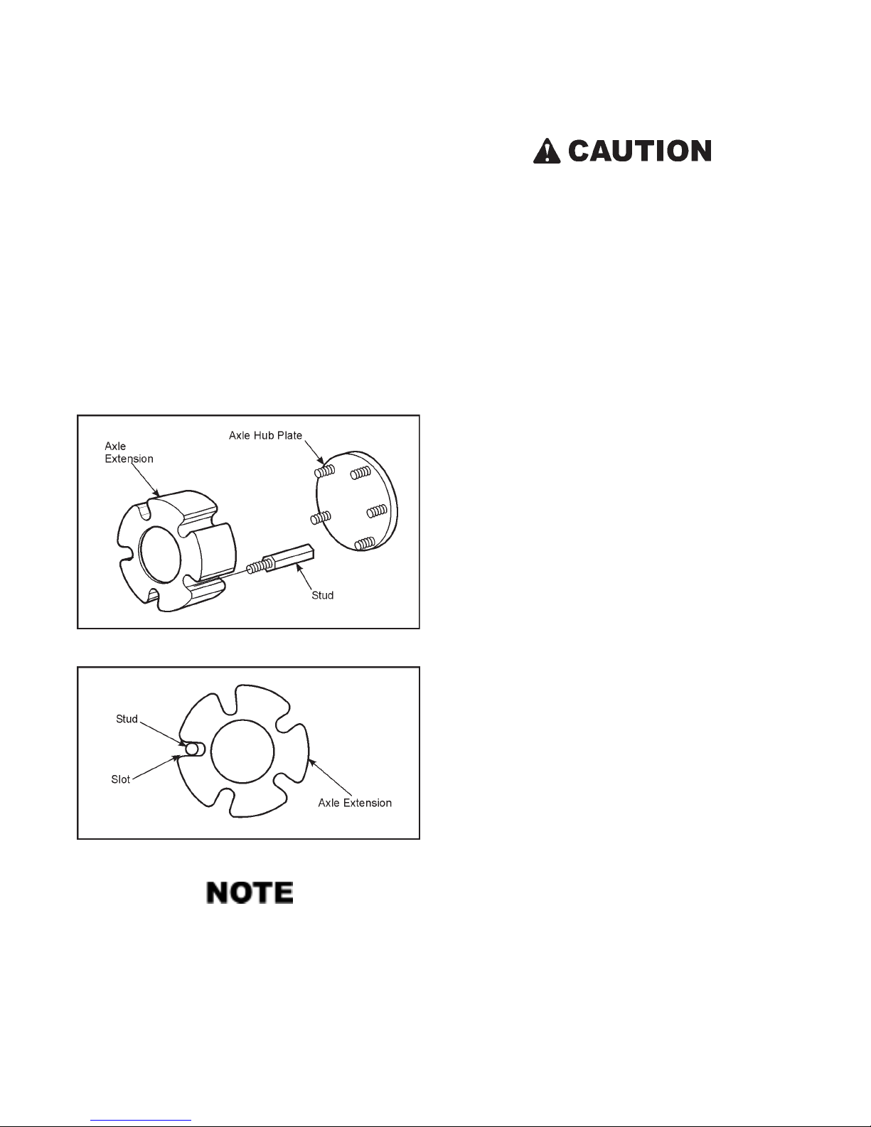
ACCESSORY INFORMATION
11.4 WINTER TRACK KIT (Part No. 849-160)
SECTION 11
Available in a ladder style, belted snow track, 22" wide for
minimal ground pressure, 1.85" steel grouser for maximum
snow penetration.
11.4.1 Installing the Axle Extension
1. Raise the vehicle off the ground and remove the wheels.
2. Install the extension studs on all of the vehicle wheel
studs and tighten securely.
3. Place the axle extension collars onto the extension studs
and seat firmly against the axle hub plate. The small hole
must face away from the hub plate.
Damage to the extension studs, bolts, or axle extension
may occur if the extension studs are not tightened correctly. Use good judgment when installing.
4. Tires must be checked for size to ensure that equal size
ones are installed on the front and rear where most of
the traction is transmitted to the tracks. If this is not done,
chain windup will happen causing damage to the drive
system components. Tires can be sized this way:
a. With the tires still off the machine, inflate them all
to 10 psi. If the tires were just installed on rims or
were left set under 5 psi, it is very important that
the tires have a chance to sit for at least 24 hours
while pressurized. Re-check the tire pressure and
re-set to 10 psi if required.
b. Measure the circumference of each tire using a suit-
able tape measure, being sure to measure around
the center-line of the tire. Figure 11-1. Write down
the measurement on each tire.
c. Try to put matched tire sizes on the front and rear of
each side; i.e. From the four tires on the left side,
choose two with a circumference within 1/2" of each
other and then put the smaller of these two on the
front and the larger one on the back. Do the same
on the right side of the Centaur.
Figure 11-5. Installing the Axle Extensions.
Figure 11-6. Check stud position in axle extension.
The extension studs have hexagonal sides and must sit
properly within the slots on the axle extension. If the
extension studs are misaligned with the slots of the axle
extensions when installing, adjust each stud as necessary by tightening them further until alignment allows
for the extension to slide on easily (by hand), up against
the axle hub.
Two tires that measure the same circumference when at
10 psi, should always be the same circumference when
at equal pressure. Check tire pressure every 10 hours
and adjust so that front and rear tires have equal pressure.
5. If tire sizing is strictly adhered to, all drive chains should
be left connected to the drive train for optimum performance. If you are experiencing frequent drive chain
windup, remove tracks and recheck tires to ensure that
front and rear tire circumference is equal with equal tire
pressure.
6. Install the Multi-Trac XT wheel assemblies. Use extreme
care and allow extra installation time to protect the axle
extensions from damage. T orque the wheel nuts to 65 ftlbs. (88 Nm).
11.4.2 Track Installation
1. Lay the two assembled tracks on the ground in front of
the vehicle so the open side of each grouser is forward.
2. Drive the vehicle forward onto the tracks until only three
segments are in front of the tires.
38
Page 47
SECTION 11
ACCESSORY INFORMATION
3. Pull the remaining track around the rear tire and forward
to the front of the vehicle.
4. Deflate the front and rear tires for easier installation of
the final track hinge bolts.
5. Join the two ends of the track and secure them in place
with C-Clamps, so that the hinges are lined up.
6. Install the track hinge bolts and secure each with a
locknut. Remove the C-clamps.
7. Inflate all tires to 10 psi (70 kPa).
8. Check track tension by raising the vehicle off the ground.
The track under the wheels should sag between 3 and 6
inches. Add air pressure, up to 20 psi, to reduce the sag.
DO NOT SET THE TRACK TENSION TOO HIGH!
High track tension will cause excessive and premature
wear of the tires and track system, and may cause axle,
axle bearing and/or chain damage.
Allow the tires to reach the temperature of operating conditions. Re-check the tire inflation at operating conditions before operation.
If a Centaur is taken outdoors into freezing temperatures after
the track system has been installed indoors at normal room
temperature, the tires will lose air pressure. After the tires
have cooled down to the outdoor temperature where the
vehicle is to be operated, the tire pressure should be rechecked and adjusted as required.
Do not allow the track to freeze up or become clogged with
snow. Damage to the track system can occur. EXTREME
CAUTION must be observed when using the track system
on icy surfaces. Loss of steering and braking effectiveness
will occur.
Extreme CAUTION is advised when crossing ice-covered
water. The vehicle will sink if it breaks through the ice surface
and fills with water.
Under certain winter conditions, such as a rapid drop
in temperature after a mild period, slush can build up
on the track system to the point that the Centaur may be
unable to move. Stop periodically to clean snow and ice
from the axles and track components to prevent buildup.
Under certain conditions, the tires may climb out of the
track system during a turn or side hill operation. Check
that all tires are correctly inflated, and avoid sharp high
speed turns when the Centaur is heavily loaded.
11.4.3 Removal of Tracks
1. Use C-Clamps to take tension off of track hinge bolt.
2. Remove the locknuts from both track hinge bolts and
remove both bolts.
3. Pull the track off the top of the tires and drive the vehicle
out of the tracks.
Axle extensions are recommended for use only with
Centaur snow tracks and should be removed for tireonly use.
11.4.4 Operating Precautions
This track system is not recommended for use on pavement,
gravel, rocks or any other abrasive surface. Abrasion will
cause damage to the track assembly.
Do NOT use the Centaur in water with any track system installed.
11.5 ICE CLEAT KIT (Part No. 848-130)
CENTAUR ice cleats are stamped steel cleats that bolt to the
all season rubber tracks to grip on hard pack snow and ice to
improve traction and stopping.
Make sure all passengers riding in a Centaur equipped
with ice cleats are informed to keep hands, feet and clothing inside the vehicle, well away from the tracks and ice
cleats while the Centaur is in motion. Serious injury or
death could result from getting caught by the ice cleats.
The Ice Cleats must be installed near the OUTSIDE edge
of the track assemblies to prevent damage to the vehicle
body.
39
Page 48
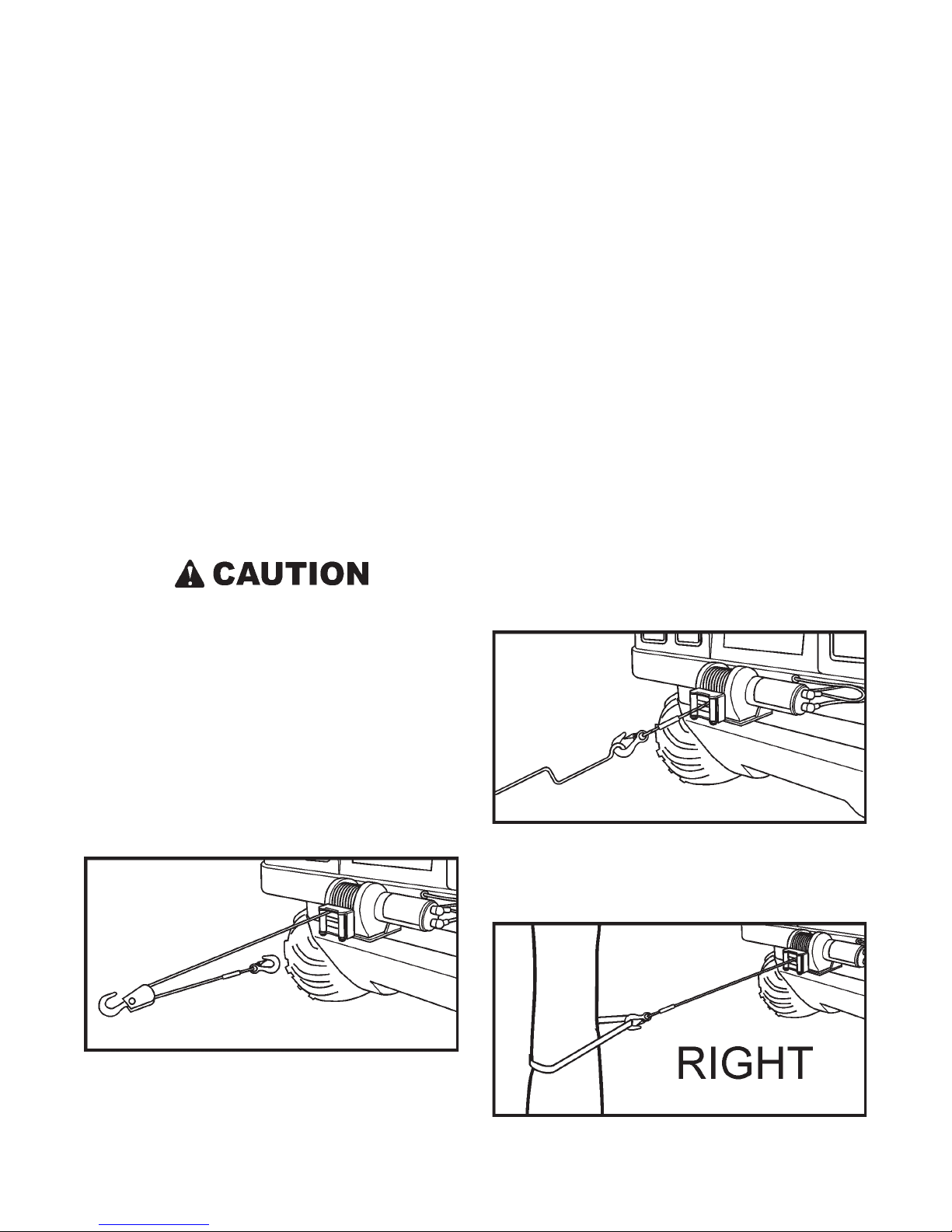
SECTION 11
ACCESSORY INFORMATION
11.6 WINCH KIT (Part No. 849-114)
The 3500 lbs. winch mounts permanently to the front of the
Centaur and can be used for self-recovery and to raise and
lower the snowplow blade (Part No. 657-100). The winch
has a free-wheeling feature that allows the 40 ft. steel cable to
be pulled off the winch drum without using the winch’s 12
volt electric motor.
The electrical components and the wiring design of the winch
kit prevent the use of the winch motor unless the ignition key
is turned to the ‘on’ position. This is a safety feature that prevents the unauthorized use of the winch when the vehicle is
parked.
After the installation of the winch kit is completed, test the
electrical connections by moving the toggle switch control
from side to side with the ignition switch removed. If the winch
DOES NOT operate, the connections are correct. If the winch
starts during this test, have the installer correct the wiring
connections immediately.
11.6.1 Rules For Safe Operation
3. DO NOT “move” your vehicle to assist the winch in pulling a load. The combination of the winch and vehicle
pulling together could overload the wire rope and the
winch itself.
4. KEEP WINCHING AREA CLEAR. Do not allow people to remain in the area during winching operations. Do
not step over a taut wire rope or allow anyone else to do
so. Do not stand between the winch and the load.
5. INSPECT WIRE ROPE AND EQUIPMENT FREQUENTLY. A frayed wire rope with broken strands
should be replaced immediately. Always replace wire
rope with the manufacturer’s identical replacement part,
Superwinch Part No.1513.
6. USE HEAVY LEATHER GLOVES when handling wire
rope. Do not let wire rope slide through your hands. A
broken strand could seriously injure your hands.
7. Keep clear of winch wire rope and hook when operating
winch. Never put your fingers through the hook when
reeling in the last few feet of line. If your finger should
become trapped in the hook, you could lose your finger.
Use the HANDSAVER BAR (Figure 11-8) to guide the
hook within the last few feet. Never guide a wire rope
onto the drum with your hand.
1. The winch is rated at 3,500 pounds (single-line) capacity. DO NOT OVERLOAD. DO NOT ATTEMPT PROLONGED PULLS AT HEAVY LOADS. DO NOT
MAINTAIN POWER TO THE WINCH IF THE MOTOR STALLS. Overloads can damage the winch and/or
the wire rope and create unsafe operating conditions. For
heavy loads, we recommend the use of the optional pulley block and hook assembly (Superwinch Part No.1503)
to double line the wire rope. (Figure 11-7) This reduces
the load on the winch and the strain on the wire rope by
approximately 50%.
Figure 11-7. Double Line.
2. Periodically check the winch installation to assure that
all bolts are tight.
Figure 11-8. Using the Handsaver Bar.
8. NEVER HOOK THE WIRE ROPE BACK ONTO ITSELF . Use a nylon sling. (Figure 11-9). Hooking the wire
rope onto itself can damage the rope (Figure 11-10).
Figure 11-9. Correct hook-up.
40
Page 49
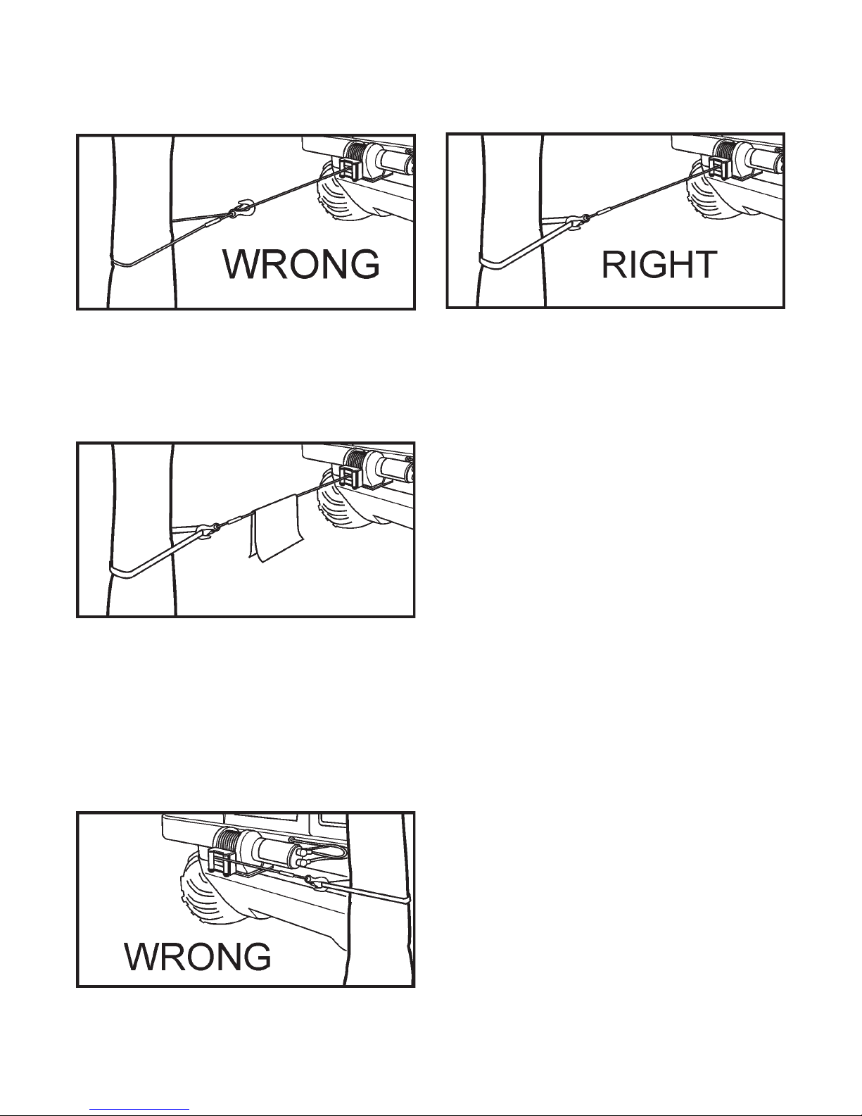
SECTION 11
ACCESSORY INFORMATION
Figure 11-10. Incorrect hook-up.
9. It is a good idea to lay a heavy blanket or jacket over the
wire rope near the hook end when pulling heavy loads
(Figure 11-11). If a wire rope failure should occur, the
cloth will act as a damper and help prevent the rope from
whipping.
Figure 11-11. Using a cloth damper.
10. Your winch is not designed or intended for overhead
hoisting operations. Never use your winch for lifting or
moving people.
11. Avoid continuous pulls from extreme angles as this will
cause the wire rope to pile up at one end of the drum
(Figure 11-12 and figure 11-13). This can jam the wire
rope in the winch causing damage to the wire rope or the
winch itself.
Figure 11-12. Incorrect positioning for continuous pulls.
Figure 11-13. Cor rect positioning for continuous pulls.
12. Always operate the winch with an unobstructed view of
the winching operation.
13. Do not operate the winch when under the influence of
drugs, alcohol or medication.
14. Never work on or around the fairlead or winch drum when
the winch is under load.
15. When using your winch to move a load, place the vehicle transmission in neutral, set vehicle parking brake,
chock all wheels, and keep the engine running.
16. Do not use the winch to hold the Centaur in place during
transportation. Use tie-down straps.
17. Maintain at least five turns of wire rope around wire rope
drum to prevent the wire rope from pulling off under
load.
18. Never run winch without circuit breakers in place. Dangerous overloads to mechanical and electrical components can result.
11.6.2 Tips for Extending the Life of Your Winch
1. Keep a tightly and evenly wound wire rope drum. Do
not allow the wire rope to become loosely wound. A
loosely-wound spool allows a wire rope under load to
work its way down into the layers of wire rope on the
drum. When this happens, the wire rope may become
wedged within the body of the windings damaging the
wire rope. To prevent this problem, keep the wire rope
tightly and evenly wound on the drum at all times. During winching, periodically check to see that the wire rope
is winding on evenly. A good practice is to rewind the
wire rope under tension after each use. One way to do
this is to attach the hook to a stationary object at the top
of a small hill or incline and winch your vehicle up the
incline.
41
Page 50
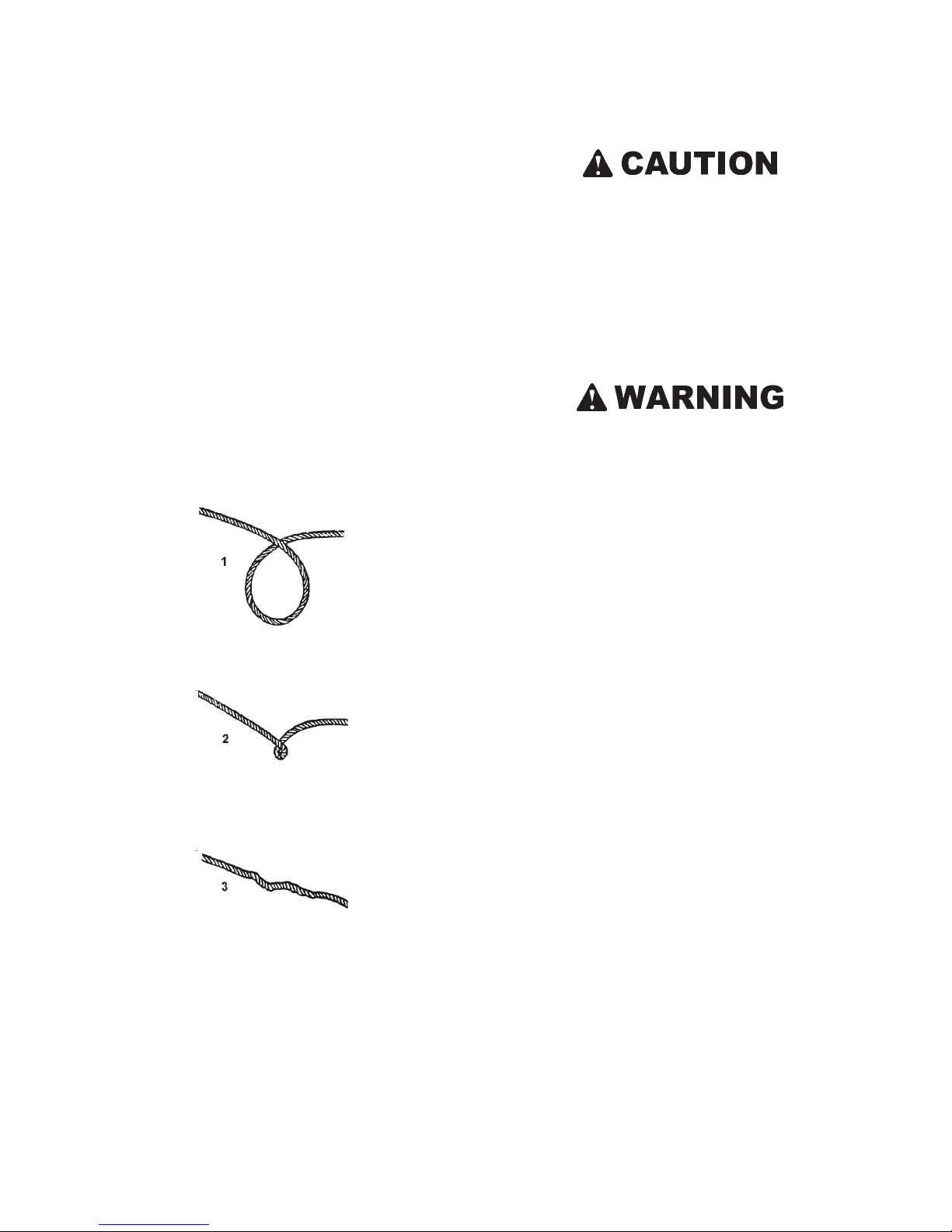
SECTION 11
ACCESSORY INFORMATION
2. Do not allow motor to overheat. Remember, the winch is
only for intermittent use. During long or heavy pulls the
motor will get hot. The internal parts will be hotter than
the case. T o check the motor temperature, stop winching
and carefully touch the end of the motor. If the motor is
uncomfortably warm, allow the motor to cool before continuing — keep the engine running to recharge the battery during this break.
3. Use a pulley block for heavy loads. To maximize winch
and wire rope life, use a pulley block (Superwinch Part
No. 1503) to double line heavier loads.
4. The pull required to start a load moving is often much
greater than the pull required to keep it moving. Avoid
frequent stopping and starting during a pull.
5. Prevent kinks before they occur.
(1) This is the start of a kink. At this time, the wire rope
should be straightened.
(2) The wire rope was pulled and the loop has tightened to a
kink. The wire rope is now permanently damaged and
must be replaced.
The pump is not designed to run dry. Use only when
water has collected in the vehicle.
11.9 SNOW PLOW KIT (Part No. 657-106)
The snow plow assembly attaches to the front mainframe assembly of the Centaur. The plow blade is an 81” (2 m) steel
blade suitable for straight or angled use. The power winch
option is required to raise and lower the snow plow blade.
DO NOT ST AND BETWEEN THE PLOW BLADE AND
THE FRONT OF THE CENT AUR. Injury could result if
the blade is raised.
The vehicle operator must observe caution when operating the vehicle and snow plow in the presence of others. Injury could result if a bystander is struck when the
vehicle swings to turn or the blade is lowered onto someone’s foot. Always be aware of the area being plowed.
Although there is a blade trip mechanism featur e of the
blade, damage or operator injury could result fr om hitting rocks, stakes or curbs hidden under the snow being
plowed.
11.9.1 Operating Guidelines
(3) The result of kinking is that each strand pulls a different
amount, causing the strands under greatest tension to
break and reduce load capacity of the wire rope. The wire
rope must be replaced.
11.7 RECEIVER WINCH KIT (Part No. 849-123)
The receiver option incorporates a winch brush guard, front
and rear receiver mounting brackets and quick disconnect
cables.
11.8 BILGE PUMP KIT (Part No. 849-146)
The bilge pump kit is recommended for amphibious use. The
Centaur utilizes two centrally located pumps to quickly remove water . It includes a dash mounted switch and wire har ness.
1. Do NOT operate the Centaur on open or frozen bodies of
water with the snowplow attached.
2. For quick removal of the snowplow unit, disconnect the
rear hitch points of the upper boom from the mounting
brackets, unhook and rewind the winch cable.
3. The knives are specially designed to be reversible and
interchangeable with each other once the leading edge
has worn.
11.10 AMPHIBIOUS TRAILER (Part No. 695-80BL)
The Centaur Four Wheel Amphibious Trailer has been designed for use as an additional cargo carrier with any Centaur
Off Road Vehicle. It is NOT intended for transporting peo-
ple.
Become familiar with the trailer’s handling characteristics,
especially in water and hilly conditions, BEFORE using it in
unfamiliar terrain or fully loaded.
The trailer tongue is designed to swivel, much like a universal joint, even in the roughest terrain.
42
Page 51

SECTION 11
ACCESSORY INFORMATION
11.11 CAB HEATER (Part No. 848-110)
DO NOT exceed maximum load capacity for your specific application.
Exceeding the load capacity could cause trailer or tow
vehicle to damage and personal injury could be incurred.
11.10.1 Operating Precautions
Observe the following recommendations for safe and trouble
free operations:
• Trailer load capacity - 600 lbs. (270 kg.). Trailer weight
- 385 lbs. (175kg.)
• Keep tire pressure at 4 psi.
• Cargo must be kept low and centered in the trailer at all
times, especially if used in water. Be aware that loads
may shift when trailer is operated in uneven terrain.
• Keep both drain plugs in place and tightly sealed. Remove floorboard for access to plugs. To tighten plugs,
turn lever clockwise. To loosen, turn counter clockwise.
To remove, lift lever and pull up on plug.
• Caution - Asphalt or concrete surfaces will cause excessive tire wear.
• Do not use in fast flowing or rough water. Operator discretion is advised.
• Do not stop suddenly when pulling a loaded trailer down
hill as it may run ahead or into the back of the vehicle
pulling it.
The Centaur can be fitted with a 17000 BTU cab heater. It is
equipped with a 3-speed dual fan motor. This will provide
operator comfort in the harshest winter conditions.
11.12 DUMP BOX KIT (Part No. 835-100)
The dump box is mounted to the mainframe. It improves the
load carrying versatility of the Centaur.
• Keep hands and arms clear when lowering box.
• No riders in box; riders can fall off and be killed.
• Installation of dump box reduces vehicle capacity by 109
kg (240 lbs). (Capacity includes: occupants, cargo and
fuel.)
• Do NOT use vehicle in water when equipped with a dump
box.
• Tie loads down. Spread loads evenly.
• Operators should use caution when turning in confined
spaces and close to bystanders. The dump box decreases
the rear clearance of the Centaur.
• Never operate dump while moving.
• Operate dump on level ground only.
• The dump box decreases the vehicle stability. Operate
the vehicle with extra precautions when on uneven terrain.
11.13 CARGO LINER (Part No. 848-123)
Made from welded steel, the cargo liner is an extension to the
existing floor plates and increases lower body protection.
Keep fingers clear of tongue swiveling components.
• Do not step on or place loads on the edge of the body
over the trailer wheels. This area of the trailer body is
intended only as a mud guard.
• Keep the outer axle bearing flanges and inner bearings
filled with Shell Alvania 2 grease, or equivalent, as this
provides extra protection for the bearings from dirt and
water.
• Remove water and debris from the trailer frequently . This
will prevent premature rusting of the frame and contamination of the bearings.
11.14 CENTAUR FOUR POINT LIFT KIT - (Part No.
848-121)
Designed for remote firefighting, search and rescue and surveying. This optional retrofitable kit mounts to all Centaur
models.
• Do not lift the Centaur with people aboard.
• Maximum lift weight of the Centaur is 2500lbs (1 134kg) which
is equivalent to the shipping weight + approximately 500lbs.
(227kg)
• Brackets are designed to be used with four equal length straps
a minimum length of 12 ft. (3.66m) each and shackles. Each
strap and shackle should be rated for 2000lbs (907.2kg) minimum.
43
Page 52

SECTION 11
ACCESSORY INFORMATION
11.15 LIGHT GUARD KIT (Part No. 849-134)
The light guards prevent brush and tree limbs from making
direct contact with the vehicle driving lights. It can be installed as a stand alone item or combined with the brush guard.
11.16 BRUSH GUARD KIT (Part No. 849-191)
The brush guard is frame mounted and designed to prevent
brush and tree limbs from damaging the lights and windshield.
11.17 MUD FLAP EXTENDERS (Part No. 821-105)
For use with Snow or Multi-Purpose Tracks. Mud flap extenders bolt onto the upper frame assembly and help to keep
mud and snow out of the cargo compartment.
11.18 TRANSMISSION OIL HEATER (Part No. 613-
103)
Recommended for use in cold temperatures. This heater plugs
into a 110V power supply and heats the transmission oil by
using a submergible 150 watt heating element.
11.19 SPEEDOMETER KIT (Part No. 849-165)
3" diameter analog dash mounted gauge, magnetic pick-up
from front drive sprocket.
44
Page 53
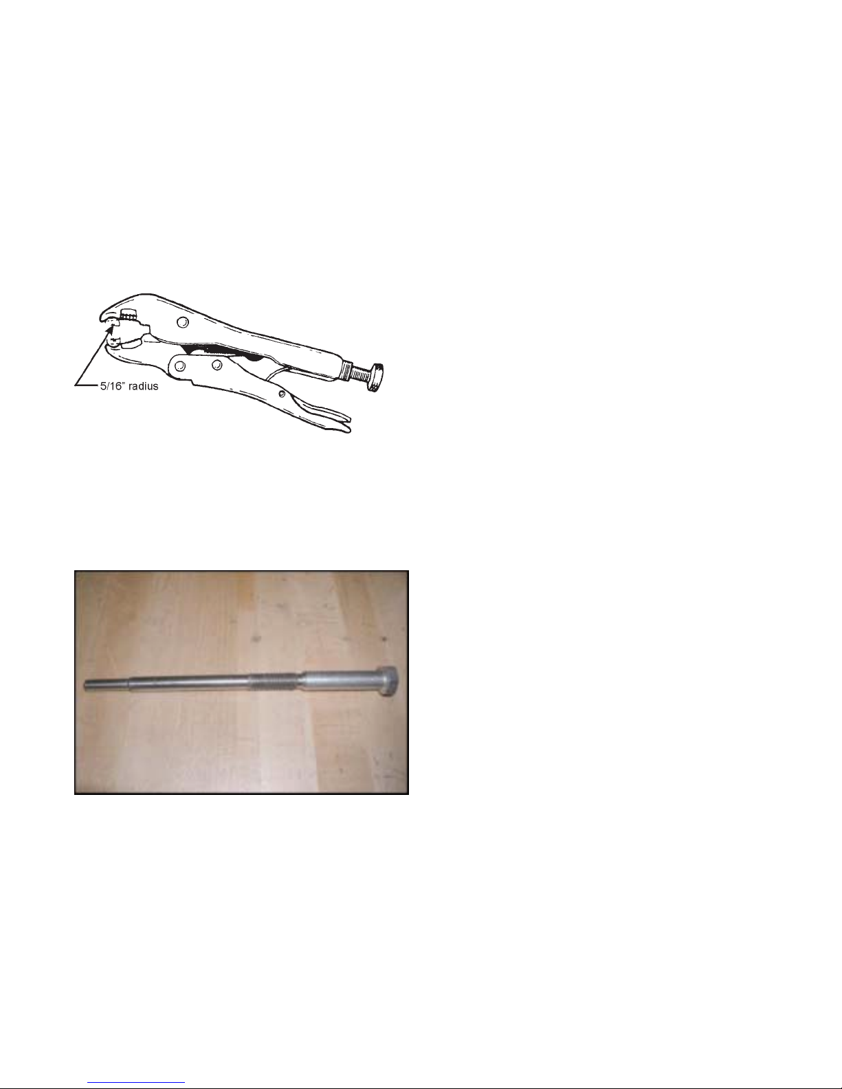
APPENDIX 1
SPECIAL TOOLS
10R VICE GRIP MODIFICA TION
As detailed in Section 7, a pair of modified 10R Vice Grips
(Part No. 658-38) is required to hold the ends of the drive
chain together while inserting the connecting link. This tool
can also be used to hold the ends of the idler chain together
while inserting the connecting link. Grind the undercut and
sides of the vice grip jaw to fit over 2 chain rollers. The undercut is approximately 5/16" radius as shown below.
DRIVER CLUTCH REMOVAL TOOL 658-17
Part No. 658-17, Clutch Removal Tool, can be used to assist
in removal of the driver clutch from the engine. Alternately , a
6” length of 3/8” steel rod can be used with a 9/16”-18x1-1/
8” bolt.
45
Page 54

NOTES
46
Page 55

Centaur New Vehicle Limited Warranty
The warranty period is limited to 12 months or 750 hours of operation from the date of retail sale, with the
following exceptions:
Engine: 24 months from the date of retail sale separately by the engine manufacturer’s service
network
Exide Battery: 12 months free replacement from the date of retail sale by the battery manufacturer service
network, 950 CCA-36 months total pro-rated, 600 CCA-60 months total pro-rated
Tires: 3 months from the date of retail sale
Ontario Drive & Gear Limited hereby warrants to the original retail purchaser that each new and unused CENT AUR
is free from any defect in material or workmanship for the warranty period specified, under normal use and service
by the original purchaser.
This warranty is void unless a Warranty Registration and Pre-Service Checklist Form 670-36 have both been
properly completed and returned to Ontario Drive & Gear Limited within 10 days of the date of retail sale.
This warranty is not transferable unless an application of transfer has been approved by Ontario Drive & Gear
Limited and a new warranty card has been issued.
This warranty shall not apply to used or demonstrator CENT AUR vehicles or to such units delivered to a distributor
or dealer more than 12 months before its retail sale, unless a warranty validation is obtained from Ontario Drive &
Gear Limited by written notice specifying the vehicle in question.
This warranty does not cover the following items:
1. Machines or parts lost or damaged during shipment.
2. Normal maintenance or adjustments after initial pre-servicing is completed.
3. Normal replacement of service items.
4. Accessory items not supplied by Ontario Drive & Gear Limited.
5. Damages resulting from:
• misuse, accident, theft or fire
• use of improper or insufficient fuel, fluids or lubricants
• use of parts other than genuine CENTAUR parts
• modifications, alteration, tampering or improper repair performed by parties other than an author-
ized CENTAUR dealer. Any device or accessories installed by parties other than an authorized
CENT AUR dealer. Modifications or alterations must be pre-authorized in writing by Ontario Drive
& Gear prior to installation
6. Batteries that fail due to improper charging or installation; broken container, cover or terminal sulphation or
dehydration; damage caused by fire, excessive heat, wreckage, explosion, freezing, the addition of any chemical
or solution other than the battery grade sulphuric acid.
This shall constitute the complete and only warranty given by Ontario Drive & Gear Limited, and, except as
specifically set forth in the foregoing, Ontario Drive & Gear Limited shall not, in any event, be liable for any
losses, damages or costs, whether special, incidental, consequential or otherwise, in any way related to any vehicle
or its sale. No warranty, expressed, implied or statutory, as to merchantability, fitness for a particular purpose,
description, quality or any other matter is given in connection with any CENT AUR vehicle or its sale and no agent,
employee or other person has any authority to vary any of the foregoing provisions. Provided, however, that this
clause shall be severable where voided by application of the Consumer Protection Act.
47
Page 56

CENT AUR RET AILER... Please complete this p age at the time of sale to the new
owner so your customer has all pertinent information that may be required.
CENT AUR MODEL ________________________________________________
CENT AUR SERIAL NO. ____________________________________________
ENGINE SERIAL NO. ______________________________________________
TRANSMISSION SERIAL NO. _______________________________________
SOLD TO: _______________________________________________________
STREET ADDRESS: _______________________________________________
CITY OR TOWN:___________________ PROV/STATE: __________________
POST AL/ZIP:_____________________________________________________
DATE OF SALE: __________________________________________________
WARRANTY PERIOD EXPIRES: _____________________________________
DEALER NAME: __________________________________________________
PHONE:_________________________________________________________
ADDRESS: ______________________________________________________
CITY/TOWN: ______________________ PROV/STATE: __________________
CENT AUR PRODUCTS MANUF ACTURED BY:
Ontario Drive & Gear Limited
220 Bergey Court
New Hamburg, Ontario
N3A 2J5 Canada
Phone: (519) 662-2840
Fax: (519) 662-2421
www.centaur8x8.ca
48
 Loading...