

Page 1

ICS Smart Indoor Repeater
for
WCDMA Mobile
User Manual
V1.0
CenRF Communications Limited
Page 2

ICS Smart Indoor Repeater
Contents
Introduction .......................................................................................................................................... 2
1 Installation ...................................................................................................................................... 3
1.1 The Setting of application ..................................................................................................... 3
1.2 Schematic Diagram of Installation ...................................................................................... 4
1.3 Description on the Indicated Info of the Overall Unit’s LCD ........................................... 6
2 Device Debugging ........................................................................................................................ 8
2.1 Preparation ............................................................................................................................. 8
2.2 Device Debugging ................................................................................................................. 8
3 Specifications .............................................................................................................................. 11
4 Precautions .................................................................................................................................. 12
CenRF Communications Limited www.cenrf.com Page 1 of 13
Page 3

ICS Smart Indoor Repeater
Following instruct application and configuration of Smart Indoor Repeater.
Introduction
These Application Instructions have provided a description, installation guide and
recommendations on the hardware of facilities in miniature ICS repeater system as well as their
software opening and debugging, including system overview, safety precautions on the installation
work, the requirements on installation site and installation preparations. You are kindly requested
to read these Application Instructions before installing and setting up the miniature ICS device and
then follow the steps and procedures described hereunder.
CenRF Communications Limited www.cenrf.com Page 2 of 13
Page 4
ICS Smart Indoor Repeater
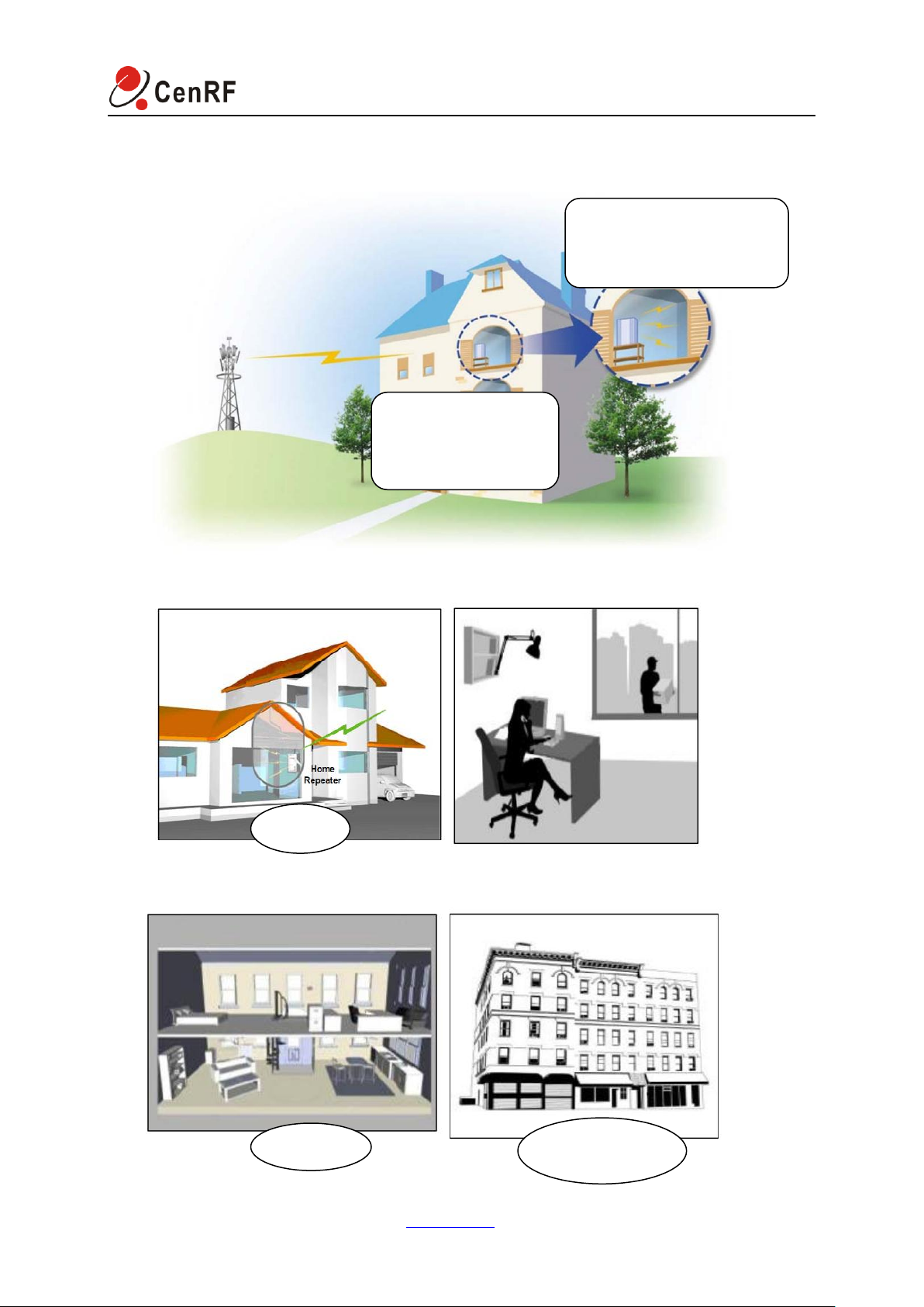
House
basement
Office building
The signal power
beside the windows≥
-85dBm will be best!
When the cover area signal
power is≤-85dBm,the effect
will be the best!
1 Installation
1.1 The Setting of application
CenRF Communications Limited www.cenrf.com Page 3 of 13
Page 5
ICS Smart Indoor Repeater
ICS Repeater
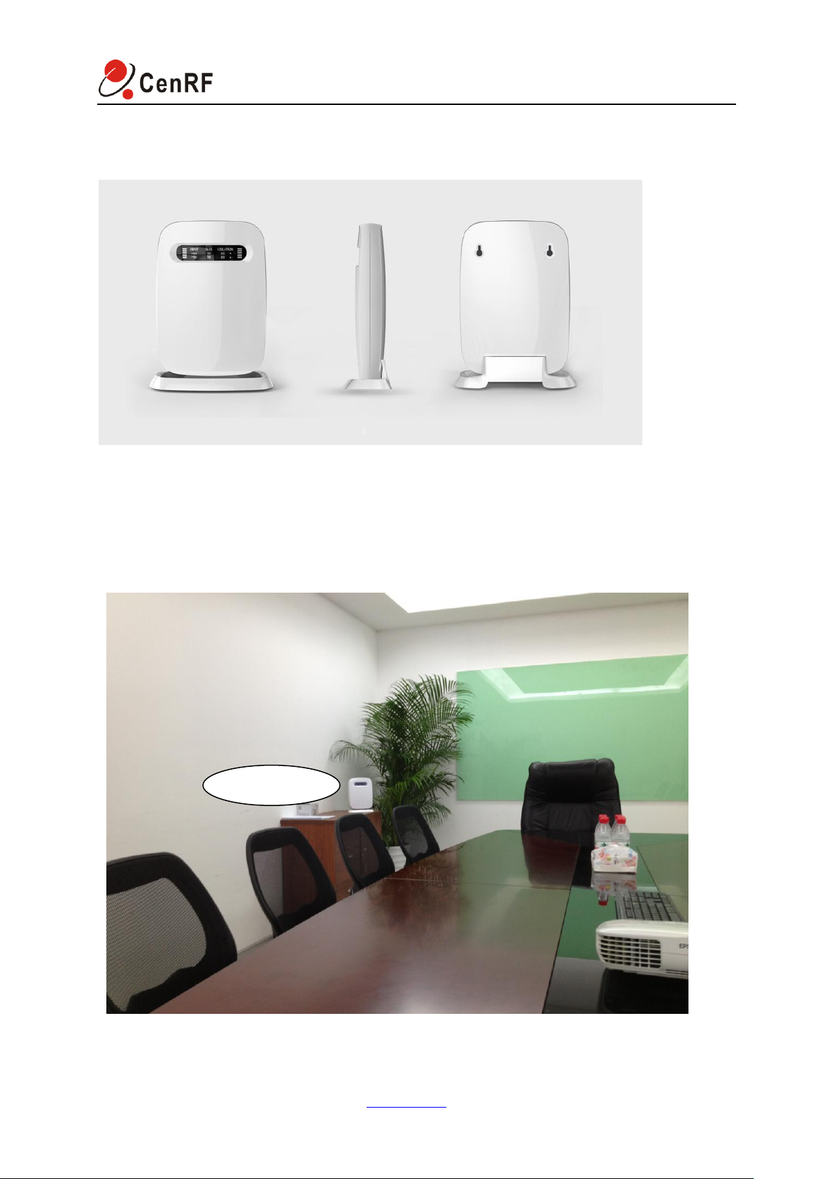
1.2 Schematic Diagram of Installation
1.2.1 The Profile of Smart Indoor Repeater Module:
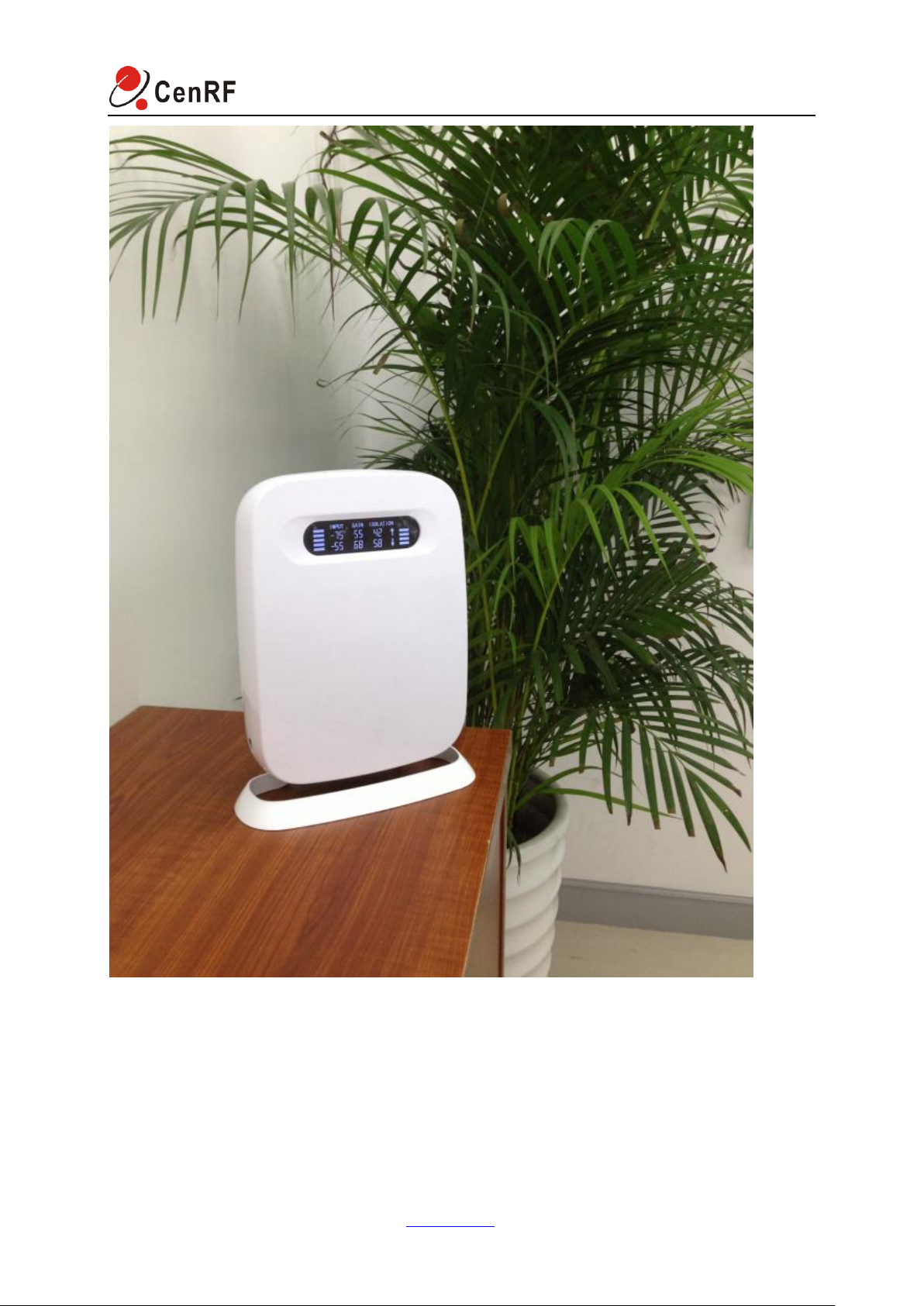
1.2.2 The setting of application for reference is shown below (with WCDMA2100MHz
application as an example)
CenRF Communications Limited www.cenrf.com Page 4 of 13
Page 6
ICS Smart Indoor Repeater
CenRF Communications Limited www.cenrf.com Page 5 of 13
Page 7
ICS Smart Indoor Repeater
LCD Indication
Description
Remarks
The Progress Bar in the left has 6
bars in total:
1. Once the module is powered on,
the Progress Bar will roll
circularly, indicating that the
module is starting;
2. Once the module is normally
started, the Progress Bar will
show the downlink received signal
level strength;
3. In case of failure in startup, all 6
progress bars would be lit,
flashing for alarm.
The indication range of downlink
signal strength:
0: no signal input or no signal
detected;
1 bar: -110~-101dBm ;
2 bars: -100~-91dBm;
3 bars: -90~-81dBm;
4 bars: -80~-66dBm;
5 bars: -65~-51dBm m;
6 bars: ≥-50dBm;
Descriptions on the Setting:
a. The ICS micropower unit is placed indoors, facing any zone to be covered; receiving and
transmitting antenna inside.
b. the uplink isolation between the receiving and transmitting antenna is 42dB and the downlink
isolation is 58dB, so the module’s gain can be generally set to be approx. 68dB.
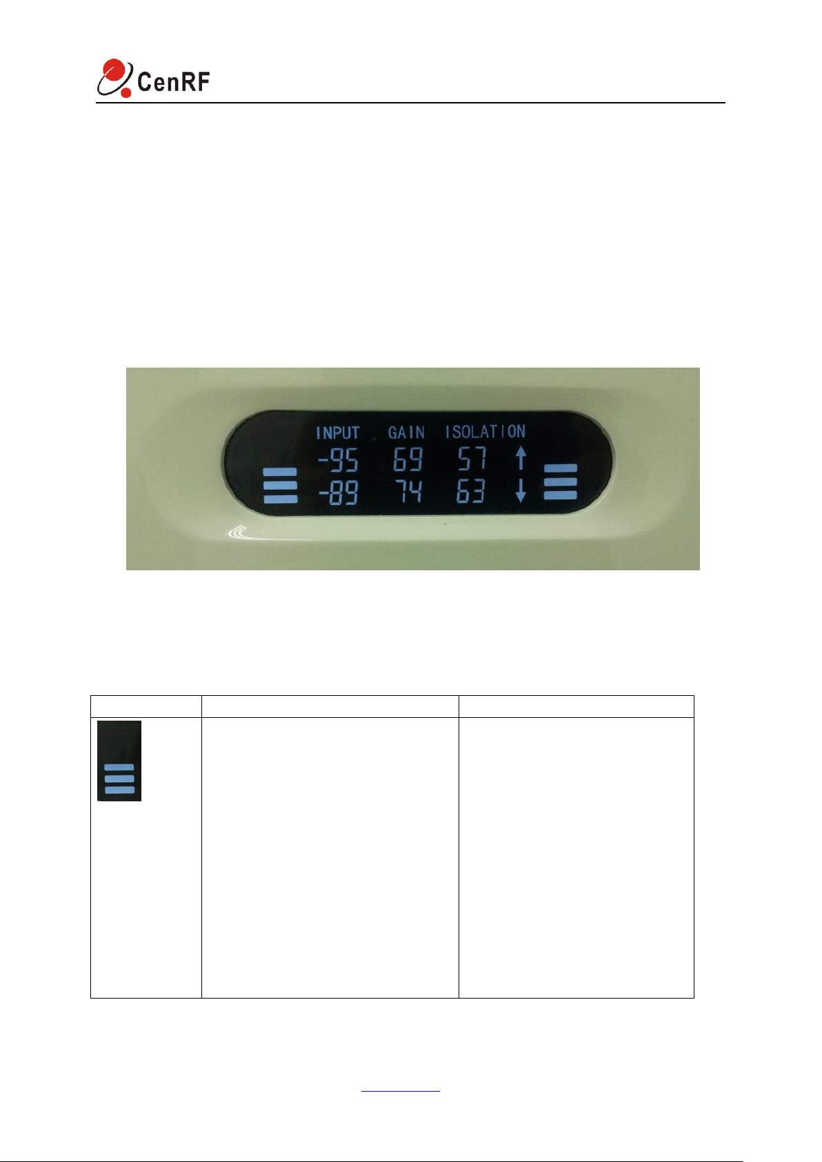
1.3 Description on the Indicated Info of the Overall Unit’s LCD
1.3.1 The Whole Profile of the LCD
1.3.2 Description on Each Indication on the LCD
CenRF Communications Limited www.cenrf.com Page 6 of 13
Page 8

ICS Smart Indoor Repeater
The uplink and downlink indications:
The UP Arrow represents uplink and
the data on the same row is
uplink-related data;
The DOWN Arrow represents
downlink and the data on the same
row is downlink-related data;
The input power value:
The data on the previous row
represents the electric level of input
power in uplink channel;
The data on the next row represents
the electric level of input power in
downlink channel.
The gain value:
The data on the previous row
represents the set gain of uplink
channel;
The data on the next row represents
the set gain of downlink channel.
Isolation:
The data on the previous row
represents the environmental
isolation of uplink channel;
The data on the next row represents
the environmental isolation of
downlink channel.
The Progress Bar in the right has 6
bars in total:
1. For the GSM system, upon
startup of module, in the process
of frequency search, the Progress
Bar will roll circularly.
2. For the GSM system, if the
frequency search failed, flashing
for alarm would occur.
3. During the normal operation, the
number of bars indicates the
condition of current working
environment.
The condition of current working
environment:
1 bar: 19~25 dB;
2 bars: 16~20dB;
3 bars: 11~15dB;
4 bars: 6~10dB;
5 bars: 0~5dB
6 bars: < 0dB
CenRF Communications Limited www.cenrf.com Page 7 of 13
Page 9
ICS Smart Indoor Repeater
Detail of Preparation
Description
Data cable
USB data cable
Computer
Computer
Configuration interface of
overall unit
ICS debugging software
(PICO_ICS_TOOL_EN.exe)
2 Device Debugging
2.1 Preparation
2.2 Device Debugging
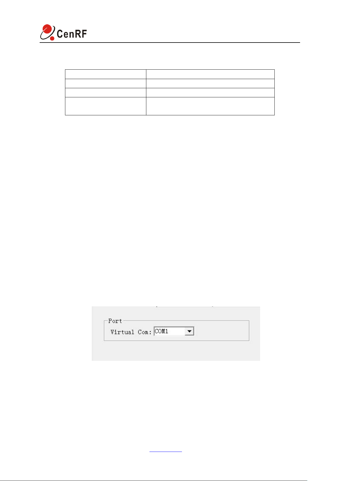
Connect the module to the power adapter, approx. 20 seconds later start up the module, then
connect USB data cable to the USB port of the computer and the overall unit and open the
ICS debugging interface.
Open the ICS debugging software (PICO_ICS_TOOL_EN.exe) interface. In case of
connection failure due to incorrect setting of serial ports, the software would pop up a dialog
box indicating connection failure. Then select the current computer’s serial port in the options
of serial port configuration. You may view the computer port in the operating sequence
(computer —— attribute —— hardware —— device manager —— port). The serial port’s
baud rate is 460800 and serial port’s configuration is shown in Figure 2.2.1. once selected
properly, you may view the monitoring interface and in case of connection failure, the basic
data of monitoring interface would be read out. Only after the serial port was properly
configured could sequent operation proceed.
Figure 2.2.1
The settings of module’s monitoring interface for reference are detailed as follows:
The following screenshot is data reading in the setting of application for reference. Please
refer to the instruction concerning the use of this interface behind each screen shot in the
configuration.
CenRF Communications Limited www.cenrf.com Page 8 of 13
Page 10
ICS Smart Indoor Repeater
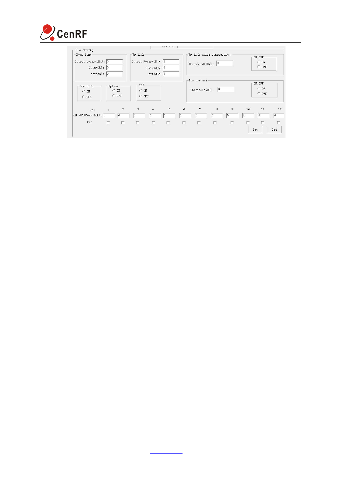
Screenshot of Downlink and Uplink Setting
Description of Basic Setting Parameters:
CH NUM: See the Specifications for the maximum number of channels supported by the overall
unit based on the practical environmental setting; Up and down the line frequency point linkage
(just Settings horizontal frequency point, ascending will automatically associated the
corresponding frequency point)
Gain: According to external isolation degree automatic Settings, the biggest gain 75 db
Output power: Module of the total output power, the default Settings for downlink 13 DBM, every
15 DBM, each channel power divide (total power divide to open each channel)
Attenuation: To set the overall unit’s gain attenuation
EN: Open and close the channel based on the number of channels used; Electromagnetic linkage
(will open channel after the uplink channel corresponding also open)
Description of Work Control Parameters:
Downlink: ON means that it is under normal operating condition;
OFF means that downlink is closed and there is no output signal from the module;
Uplink: ON means that it is under normal operating condition;
OFF means that downlink is closed and there is no output signal from the module;
ICS: ON means that the feedback inhibition function is enabled (the uplink and downlink of this
switch must be under the same condition, i.e. switch on or off simultaneously);
OFF means that the feedback inhibition function is disabled;
Up link Noise Suppression: Select Not Working;
ICS protect: Select Working.
Threshold(dB): Gain binding isolation degree value (suggest setting for 17)
CenRF Communications Limited www.cenrf.com Page 9 of 13
Page 11
ICS Smart Indoor Repeater
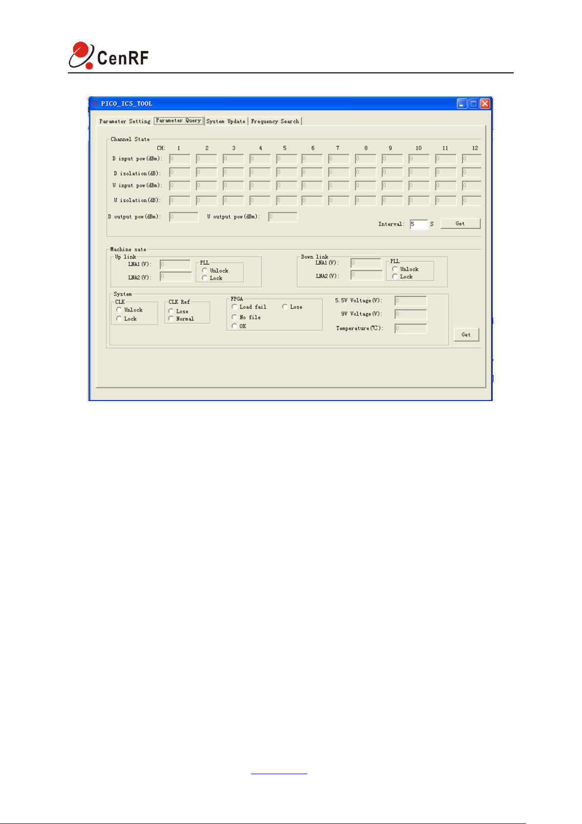
Downlink and Uplink Data Reading
Description on Parameters Requiring Special Attention:
Input Power: The enabled channel’s input power value, used for indicating the power of signal
received by the donor antenna;
Isolation: The isolation between the donor antenna and the retransmission antenna;
The Overall Unit’s Actual Output Power: The module’s actual output power in total.
Machine sate: And do some monitoring parameters, the condition of LNA, the state of the PLL
System: Clock, the clock reference state, logic state of loading
CenRF Communications Limited www.cenrf.com Page 10 of 13
Page 12
ICS Smart Indoor Repeater
Parameter
Uplink
Downlink
Frequency Range
1920MHz-1980MHz
2110MHz-2170MHz
Bandwidth
15MHz (Continuous 3 carrier)
Gain
75dB±3dB
Output Power
15dBm±3dB
15dBm±3dB
Gain Adjustment Range
30dB, Step 1dB
Max. Damage Input Power
-10dBm
Gain Adjustment Step Error
≤1dB (1-20dB); ≤1.5dB / (20-30dB)
ALC
>20dB
Ripple in Band
≤3dB p-p
ACRR
≥20dB offset ±5MHz;
≥20dB offset ±10MHz
Noise Figure
≤6dB
≤6dB
VSWR
≤2.0
Frequency stability
0.01ppm
Time Delay
≤10.5us
EVM
≤ 12.5%@75dB
Intermodulation
Comply with 3GPP TS 25. 106
Automatic Gain Control
≥30dB
PCDE
≤-35dB
Out of band Rejection
≤ 60dB @ 2.7MHz≤f_offset <3.5MHz
≤ 45dB @ 3.5MHz≤f_offset <7.5MHz
≤ 45dB @ 7.5MHz≤f_offset <12.5MHz
≤ 35dB @ 12.5Mhz ≤f_offset
Spurious emission
In band:
2.515MHz<f_offset<2.715MHz: ≤-22dBm/30kHz
2.715MHz<f_offset<3.515MHz: ≤-22dBm/30kHz
3.515MHz<f_offset<4.0MHz: ≤-34dBm/30kHz
4.0MHz<f_offset<8.0MHz: ≤-21dBm/1MHz
8.0MHz<f_offset<f_offsetmax: ≤-25dBm/1MHz
Outoff Band:
9kHz~150kHz≤-36dBm/1kHz
150kHz~30MHz≤-36dBm/10kHz
30MHz~1GHz≤-36dBm/100kHz
1GHz~12.75GHz≤-30dBm/1MHz
Local Control interface
USB
Power Supply
AC220V
Power Consumption
18W
Working Temperature
-10℃ to +40℃
Dimension
270*210*65mm
Weight
1.8KG
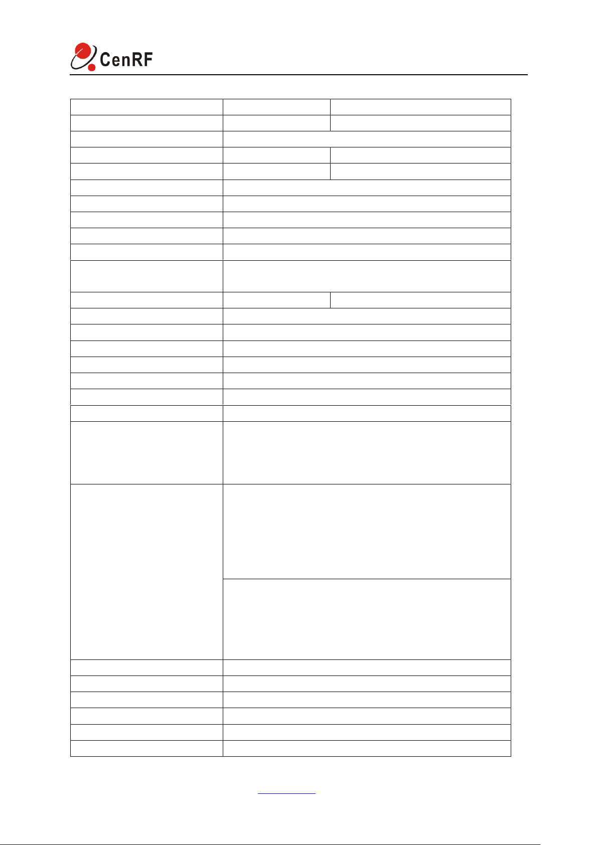
3 Specifications
CenRF Communications Limited www.cenrf.com Page 11 of 13
Page 13

ICS Smart Indoor Repeater
4 Precautions
4.1.1 Assure the quality of signal at the location of donor antenna to the greatest extent;
4.1.2 Maintain the isolation between the donor antenna and the ICS overall unit;
4.1.3 Keep the ICS micropower unit and the antenna over 1m away from the range of
human activity as possible practically;
4.1.4 Put the micropower unit and the antenna on a higher place as possible practically;
4.1.5 When setting the interface, the uplink gain is generally 5dB less than the downlink gain
and the uplink output power is generally set to maximum.
------------------------------------------------------------End----------------------------------------------------------------
CenRF Communications Limited
Address: Dongguan Building, Jiangnan Ave 4288, Binjiang District, Hangzhou City 310053, China.
Tel: +86-571-86631886
Fax: +86-571-89930536
Technical Support hotline: +8618058168088
Online support Skype ID: woofoch
Complaints E-mail: [email protected]
www.cenrf.com
CenRF Communications Limited www.cenrf.com Page 12 of 13
 Loading...