

Page 1
N9745 Bracket/Harnesses Assembly Kit
for N1611 Alternator
Replacement Instructions
To replace the bracket assembly on the
N1611 anti-drive end (ADE) housing:
1. See N1607/N1611 Service Manual SM0030A:
Follow steps 3 and 4 to uncover ADE rectifier/
housing assembly.
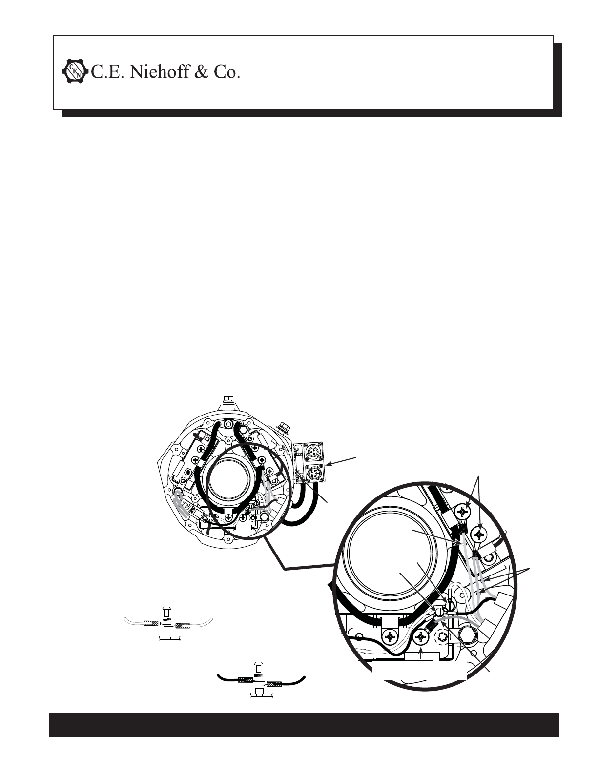
See Figure 1 below and:
2. Disconnect wire terminals from both wiring
harnesses at diode modules, saving hardware
for reassembly.
3. Pull grommets and harness wires through holes in
housing. Some wire terminal ends will need to be
snipped off to clear hole diameters.
4. Loosen four screws holding J2 harness to bracket.
Discard J2 harness.
5. Remove and discard bolts and lock washers
attaching old bracket to housing. Be careful not to
damage threads in housing when removing bolts.
Remove and discard bracket with J1 harness.
6. Attach new bracket and harnesses assembly to
housing:
a. Install bracket in position, hand-tighten with
one bolt and lock washer in hole
nearest J1 harness.
b. Loosen four screws
holding J2 harness
to new bracket.
Pull harness far
enough away
from bracket
to access the
second bolt hole
in the bracket.
J2
J1
c. Install second bolt and lock washer in position.
Torque both bolts to 13.5 Nm/120 lb. in.
d. Tighten four screws holding J2 harness to
bracket, torquing to 1.2 Nm/10 lb. in.
7. Install new grommets in holes in housing.
8. Feed harness wires through grommets. Lubricate if
necessary. See Figure 1.
9. Attach new terminals to harness wires.
a. Field connection terminals shown in Details A
and B: Insert new regular sleeves. Crimp and
solder new terminals on wires. Slide regular
sleeves over their soldered connections.
b. Remaining three connections: Insert new shrink
sleeves on wires as shown in Close-up. Brown
wires are combined into one shrink sleeve.
Crimp and solder new terminals on wires. Slide
shrink sleeves over soldered connections. Use
heat gun to tighten sleeves.
10. Clean old RTV coating from diode modules.
11. Secure wire terminals as shown in Close-up and
Details A and B. Torque screws as indicated.
12. Coat electrical terminals with Dow Corning®1–2577
Low VOC RTV coating or equivalent. Do not use
coating containing acetic acid (vinegar smell) on
electrical components.
13. Follow steps 9 and 10 in service manual to complete
assembly of alternator.
Screws
(4 plcs)
J2 bolt
Red wire
Torque to 7.4 Nm/
65 lb. in.
Figure 1 – N1611 ADE Rectifier/Housing Assembly
with N9745 Bracket Assembly
White wire
from gray
connector
Detail A—Stacking Order
Torque 15-18 lb. in.
White wire
from
J2 harness
Torque 15-18 lb. in.
Black wire
from gray
connector
Detail B—Stacking Order
Black wire
from
J1 harness
Detail A
Detail B
Torque to 7.4 Nm/
65 lb. in.
J2
Green
wire
Close-up
2 Brown
wires
J1
C. E. Niehoff & Co. • 2021 Lee Street • Evanston, IL 60202 Tech Services Hotline 800-643-4633
Page 1 of 1
II0159A
 Loading...