

Page 1
N1304-1 Alternator to N1380-2 Alternator
.
C. E. Niehoff & Co
BRUSHLESS ALTERNATORS
The following terms are used to bring attention to the presence of hazards of various risk levels or to important information
concerning product life.
DANGER
CAUTION
Indicates the presence of
hazards that will cause severe
personal injury, death, or
substantial property damage if
ignored.
Indicates the presence of
hazards that will or can cause
minor personal injury or property
damage if ignored.
Using N7359-1 Conversion Kit
Conversion Instructions
NOTICE
Indicates special instructions on
installation, operation, or maintenance that are important, but
not related to personal injury
hazards.
NOTICE
DANGER
All hardware should be saved
for reuse unless otherwise
noted.
Do not allow hardware to drop
inside alternator. Loose hardware inside alternator cavity or
stator windings or field coil
will cause substantial
equipment damage.
Disassembly
1. To make reassembly easier, mark the following
junctions:
a. anti-drive end housing and shell.
b. drive end housing and shell. Transfer the
mark from the existing drive end housing
to the same location on the new drive end
housing.
2. Remove and save pulley (if installed), Woodruff
key, and pulley bushing on drive end.
3. Remove and discard:
a. regulator hardware and regulator.
b. control unit front cover hardware and
control unit front cover.
3. Remove and save nut and washer holding fan on
anti-drive end of shaft. Remove and save fan.
b. Use three 10-32 jacking screws to lift rotor
off core.
CAUTION
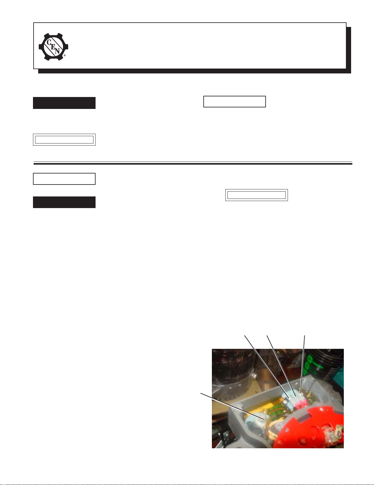
6. Inside control unit, remove coating material
covering three terminal leads and B+ stud.
7. Remove hardware holding three terminal leads
and B+ stud. Remove the three leads and the
leads from the B+ stud. See Figure 1.
8. Mark leads for reassembly and carefully pull
three terminal leads from coating material so as
not to damage leads. Clean coating material from
leads. Check terminals for rust or corrosion and
clean with wire brush if necessary.
9. Remove output lead attached to B+ stud.
Ground terminal
lead from heat
sink
F–
terminal lead
This method may
damage rotor if rotor
is rusted to core.
F+
terminal lead
4. Remove and save nuts holding anti-drive end
housing. Remove and save anti-drive end
housing. Bearing and seals should remain
on shaft.
5. Remove and save one nut and washer from
anti-drive end rotor. Mark across middle of
hole on face of rotor to realign rotor on shaft
core. Remove and save remaining nuts and
washers, then remove and save rotor.
a. To loosen rust, use an air chisel with a
rounded-point hammer bit to vibrate area
between screw holes on rotor face.
— OR—
II0063A
B+ stud and
output lead
from heat
sink
TT
T
TT
TT
T
TT
TT
T
TT
TT
TT
T
Figure 1—Control Unit Connections
Page 1
Page 2
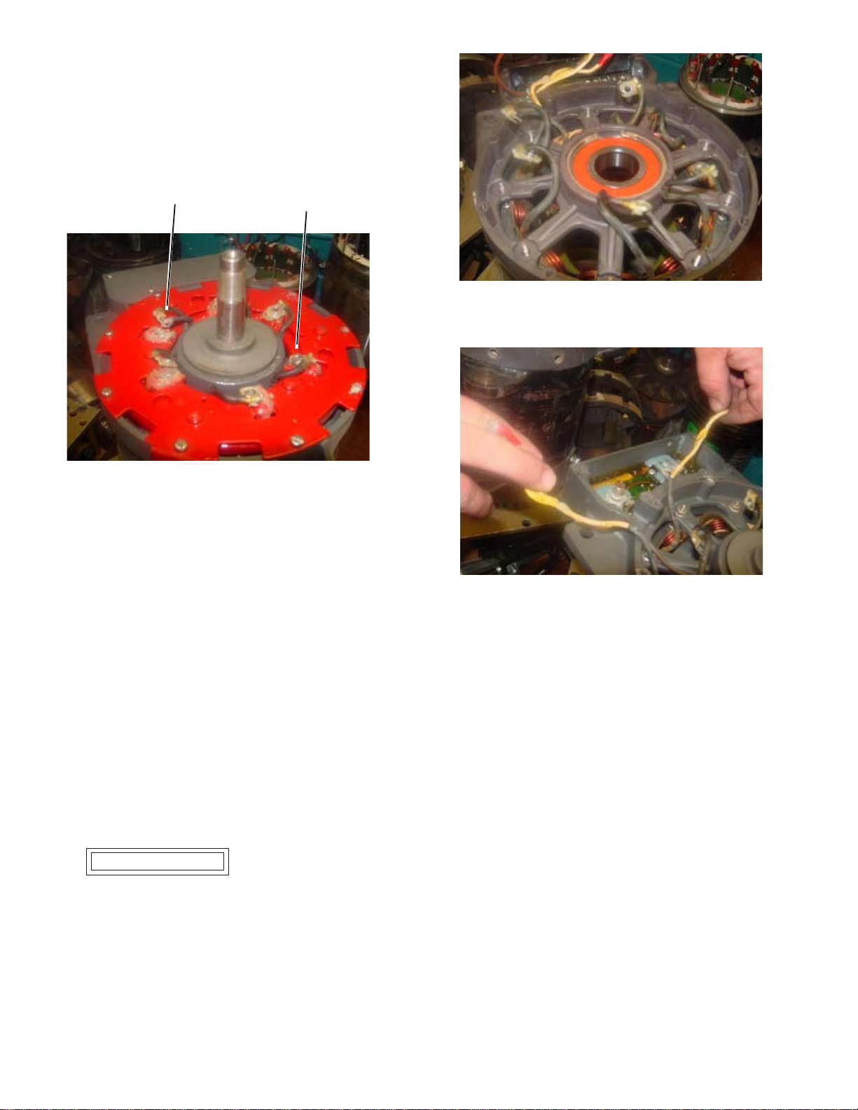
10. Remove and save hardware holding stator leads
and phase lead (attached to stator lead (at 10:00
position) to heat sink assembly. See Figure 2.
Clean coating material from leads. Check terminals for rust or corrosion and clean with wire
brush if necessary.
Phase lead
TT
T
TT
TT
T
TT
TT
T
TT
Figure 2—Phase Lead and Stator Leads Connections
11. Remove and save heat sink hardware (including
ground bolt and lockwasher on tab on side of
housing) and heat sink assembly.
12. Remove and save drive end housing hardware.
13. Remove drive end housing from shell.
Stator lead
(one of six)
TT
T
TT
Figure 3—Phase Leads and Field Coil Leads
Figure 4—Field Coil Leads
14. Press shaft out of bearing in drive end housing.
Discard drive end housing and bearing. Save
shaft core/drive end rotor assembly.
Assembly
1. New drive end housing has bearing and retaining
rings installed at factory. Using CEN A10–109
bearing tool or equivalent placed on bearing
inner race, press shaft into bearing in DE
housing. Rotate shaft to make sure bearing
moves freely.
2. Support shell/field coil/stator assembly on
blocks while installing DE housing and shaft.
CAUTION
3. Align scribed marks, then set housing assembly
in position. Pull stator leads and field coil leads
through vent holes in assembly. See Figures 3
and 4. Securely mate housing to shell. Rotate
shaft to make sure rotor does not interfere with
stator leads or field coil leads.
Do not damage stator
windings or through-studs
while assembling DE housing and shell. Make sure
support is tall enough so
that shaft clears bench.
4. Install existing locknuts on through-studs. Use
a suitable adhesive, such as Loctite® 222.
Follow manufacturer’s instructions. Torque
locknuts to 2-2.25 Nm/18-20 lb. in.
5. Guide field coil leads through channel in housing. See Figure 2. Attach field coil leads to
terminal block. See Figure 1 for correct locations. Tighten screws just enough to firmly hold
leads in terminal block. Wire-tie field coil leads
together inside channel.
6. Install heat sink assembly, guiding stator leads
and phase lead through center opening to their
respective positions. See Figure 2.
7. Install existing hardware to hold heat sink in
position. Use a suitable adhesive, such as
Loctite
tions. Torque screws to 2-2.25 Nm/18-20 lb. in.
8. Loosely install ground bolt and lockwasher in
tab on side of heat sink into housing.
9. Install ground lead in terminal block. Tighten
screw just enough to firmly hold leads in terminal block. See Figure 1 for position.
®
222. Follow manufacturer’s instruc-
Page 2
II0063A
Page 3
10. Remove two top nuts on B+ stud and discard
one nut. Install output lead and remaining nut
on B+ stud and tighten firmly enough to hold
output lead on stud.
CAUTION
11. Connect stator leads and phase lead to proper
stator terminals as shown in Figure 2. Torque
hardware to 3.4 Nm/30 lb. in.
12. Coat stator terminals and terminal block and
B+ stud terminal inside control unit with Dow
Corning
not use coating containing acetic acid (vinegar
smell) on electrical components.
13. Install new control unit cover on control unit
with tab on top facing out. Use a suitable adhesive, such as Loctite
Follow manufacturer’s instructions. Torque
screws to 2-2.25 Nm/18-20 lb. in.
14. Remove and discard two existing screws on top
of control unit.
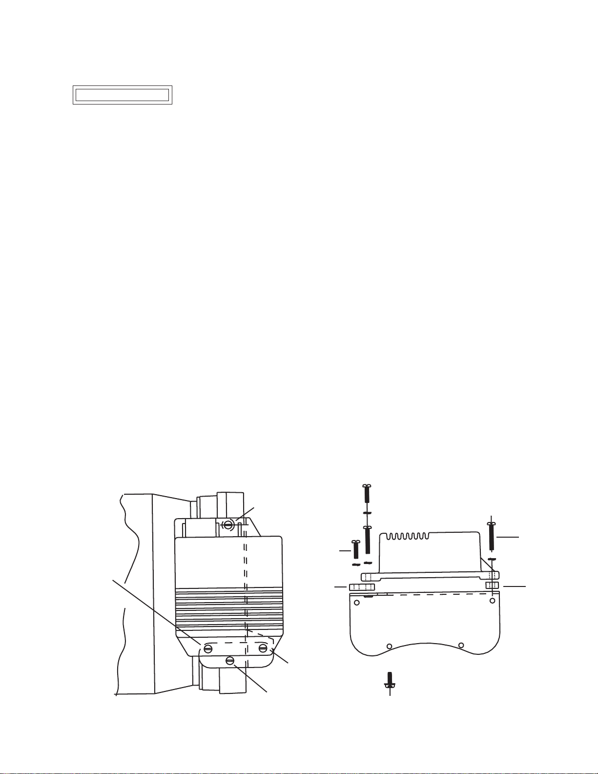
15. Place bracket, spacer, and regulator on top of
control unit as shown in Figure 5.
16. Use a suitable adhesive, such as Loctite
new hardware. Follow manufacturer’s instructions. Loosely install (see Figure 5):
a. one long screw and washer in regulator
b. remaining long screw and washer in front
c. one short screw and washer in rear regulator
d. remaining short screw and washer in
17. Torque screws in a-b-c-d order listed in step 16
®3
3140 RTV coating or equivalent. Do
mounting hole above spacer.
regulator mounting hole above bracket.
mounting hole above bracket.
bracket.
Out put terminal may
be damaged if nut is
overtightened.
®
222 on new hardware.
®
222 on
to 2-2.25 Nm/18-20 lb. in.
18. Place ADE rotor on shaft. Align scribe mark.
Loosely install all nuts and washers except for
the nut for the marked hole. Before securing
nuts, make sure scribe mark in last hole is
aligned. Then secure all nuts. On all screws, use
a suitable adhesive, such as Loctite
Follow manufacturer’s instructions.Torque to
3.4 Nm/30 lb. in.
19. Align scribed marks, then set ADE housing
assembly in position on shell. If bearing remained in housing, use CEN A10–109 bearing
tool or equivalent placed on bearing inner race.
Press on bearing and guide ADE housing on
shell. Rotate shaft to make sure bearing moves
freely.
20. Install existing locknuts on through-studs. Use
a suitable adhesive, such as Loctite
Follow manufacturer’s instructions. Torque
locknuts to 2-2.25 Nm/18-20 lb. in.
21. Press fan assembly into bore of ADE housing.
Fasten with existing hardware and torque to
67.8 Nm/50 lb. ft.
22. Install pulley bushing on drive end shaft with
short hub facing bearing.
23. Install Woodruff key in slot in shaft.
24. Install pulley on shaft. Torque to 162.7 Nm/
120 lb. ft.
25. Plug regulator harness plug into regulator
receptacle in housing.
®
222.
®
222.
Test unit on bench to verify proper operation
after assembling.
Short screw -
step 16c
II0063A
Long screw -
step 16a
TT
TT
T
Short
screw
Bracket
T
TT
TT
TT
T
T
TT
TT
Figure 5—New Regulator and Bracket Assembly
TT
Long screw -
step 16b
Short screw -
step 16d
TT
TT
T
TT
TT
T
TT
TT
T
TT
TT
T
Long
screw
Spacer
Page 3
Page 4

Page 4
II0063A
Page 5

Service Parts List * N1380-1 Date: 09/03/04
y
y
t
g
y
y
y
y
y
g
y
g
y
y
No. Part No. Qty. Description
Ke
1A N9001 1 Pulle
2 N7212 1 Fan
3 N7403 1 Front Housing & Control Uni
3A N9009 1 Retaining Ring (Beveled)
3B N9010 1 Front Bearing
3C N9008 1 Retaining Rin
3D N7368 1 Cover Plate, Plug Nut Assembl
3E N9450 1 Bracket
4 N7449 1 Rotor, Shaft & Core Assembl
4A N7003 2 Rotor Assembl
4B N7278 1 Core & Shaft Assembl
5 N7280 1 Shell, Stator, Field Coil Assembl
6 N7281 1 End Housing
6A N9302 2 Bearing Seals
6B N9303 1 Rear Bearing (Roller)
6C N9405 1 Tension Bushin
7 N7227 1 Heatsink Assembl
8 N3109 1 Regulator
10 N8051 1 Small Parts Packa
1001 N9265 17 Lockwasher (#8 .17"ID x .30"OD x 040" T SST)
1002 N9186 13 TXT-20 Screw (8-32UNC-2A x .37"L)
1003 N9039 6 Pan Head Screw (10-32UNF-2A x .37"L)
1004 N9018 6 Lockwasher (#10 .20"ID x .33"OD x .05"T SST)
1005 N9016 6 Flat Washer (.20"ID x .375"OD x .040"T SST)
1006 N9014 1 Bolt (5/16-16UNC-2A x .75"L)
1007 N9015 1 Lockwasher (.32"ID x .60"OD x.08 "T SST)
1008 N9399 2 Pan Head Screw (8-32UNC-2A x .62"L)
1009 N9400 2 Pan Head Screw (8-32UNC-2A x 1.0"L)
1010 N9447 1 Spacer (.18"ID x .50"OD x .25"T STL)
1011 N9218 1 Hex Nut (3/8-16 Zn)
1012 N9099 18 Flange Locknut (8-32 S-Grip)
1013 N9091 12 Locknut ((10-32UNF-2B)
1014 N9320 12 Flat Washer (.200"ID x .437"0D x 031"T)
1015 N9040 1 Woodruff Ke
1016 N9217 1 E
1017 N9063 1 Flat Washer (.53"ID x 1.06"OD x .09"T BLKOXD.)
1018 N9092 1 Locknut (1/2-20UNF-2B ZN)
*1019 N9587 12 Torx Screw Taptite (10-32 x .5"L)
Bushing (.785"ID x 2.79"OD x .695"T)
e
(3/16" x 3/4")
ebolt / Nut (3/8-16UNC-2A x 1.75"L)
* - Part not shown on Exploded View.
C. E. Niehoff & Co. • 2021 Lee Street • Evanston, IL 60202 Tech Services Hotline 800-643-4633
II0063A
Page 5
 Loading...