

Page 1
N1381 Alternator
.
C. E. Niehoff & Co
BRUSHLESS ALTERNATORS
The following term is used to bring attention to the presence of hazards of various risk levels or to important information concerning product life.
Using N7300 Conversion Kit
Conversion Instructions
DANGER
B+
cables
Resistor
lead
Resistor
lead
Resistor
Indicates the presence of hazards that will cause severe personal injury, death, or substantial
property damage if ignored.
terminal lead
TT
TT
T
T
TT
TT
Resistor
leads
TT
TT
T
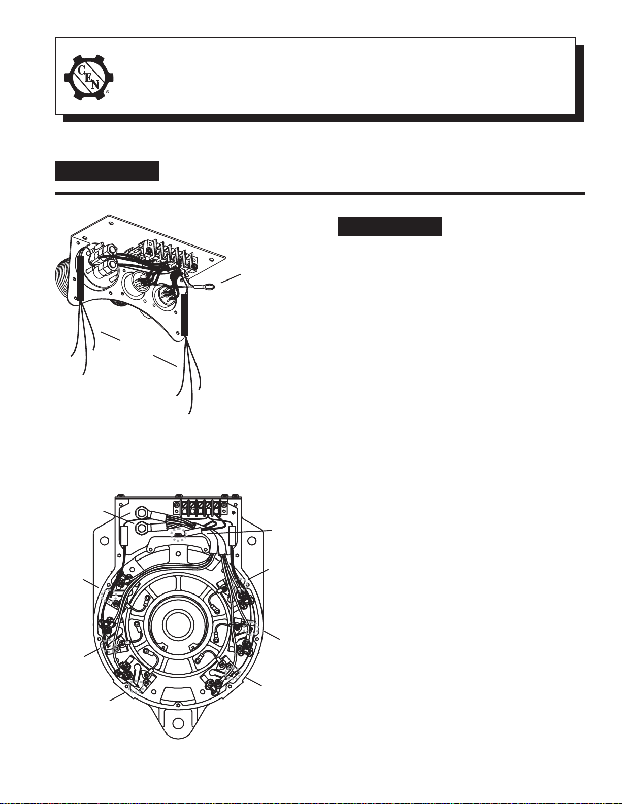
Figure 1—New Control Unit Assembly
T
TT
TT
TT
TT
lead
TT
TT
T
T
TT
TT
T
TT
TT
T
TT
TT
T
Ground
TT
TT
T
T
TT
TT
T
TT
TT
Resistor
Ground
terminal
lead
Resistor
lead
Resistor
lead
lead
DANGER
Do not allow hardware to drop
inside alternator. Loose hardware inside alternator cavity or
stator windings or field coil
will cause substantial
equipment damage.
Disassembly
1. Disconnect B+ cables from inside the control
unit.
2. Unsolder resistor wires from modules.
3. Remove potting from control unit.
4. Remove screws holding control unit assembly to
housing.
5. Remove and discard control unit assembly.
6. Clean old potting from inside control unit.
Assembly
1. Attach new control unit assembly (see Figure 1)
to housing. Use suitable adhesive, such as
Loctite® 222. Follow manufacturer’s instructions. Torque new hardware to 5 Nm/45 lb. in.
2. Connect B+ cables inside the control unit.
Torque hardware to 15 Nm/135 lb. in.
3. Using hardware provided in kit, attach ground
terminal lead from control unit terminal strip to
threaded hole in top of casting. See Figure 2.
Torque new hardware to 5 Nm/45 lb. in.
4. Using standard solder, connect the six resistor
leads to the points shown in Figure 2.
Figure 2—Drive End (DE) Housing Connections
II0068A
Page 1
Page 2
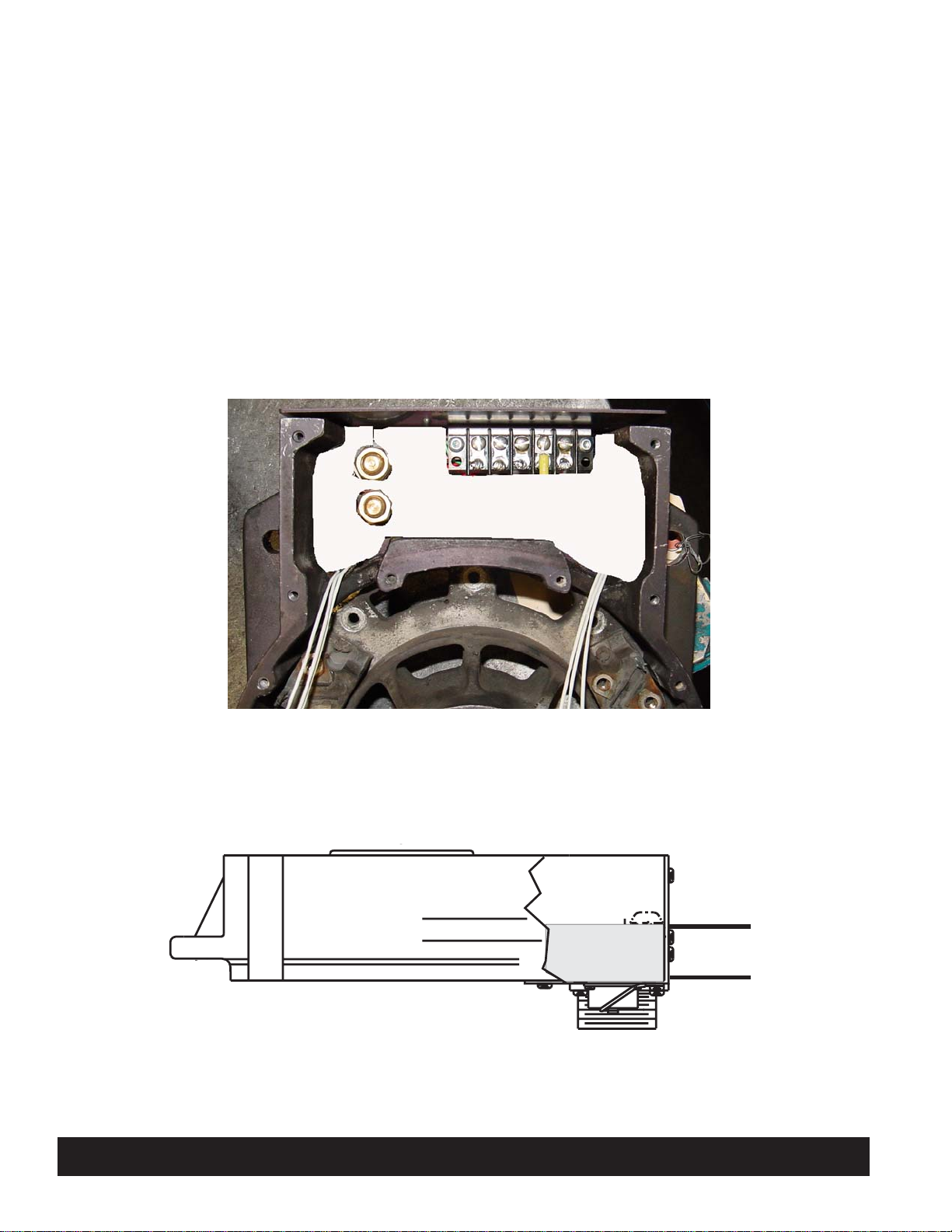
5. Fill the cavity inside control unit with GE Silicones® RTV11® silicone (2 part) or equivalent
(see Figures 3 and 4):
a. Mix 74 drops of cure per 1/2 cup of RTV.
Blend well to prevent incomplete deep-set.
At this point, there is a half hour before
mixture thickens and two hours until mixture deep-sets.
b. Make sure resistor assemblies are pressed
into bottom of cavity. Resistors and their
sleeves must be completely covered with new
silicone. See Figure 3.
c. Pour mixture into cavity until it reaches the
bottom of the screws in the terminal strip.
See Figure 4.
6. Continue assembling DE housing.
Figure 3—Fill Area of Control Unit
Fill cavity to
this level
Figure 4—Fill Level of Control Unit
C. E. Niehoff & Co. • 2021 Lee Street • Evanston, IL 60202 Tech Services Hotline 800-643-4633
Page 2
II0068A
 Loading...