

Page 1
Troubleshooting Guide
for N2013 Battery Isolator
Hazard Defi nitions
This term indicates special instructions
NOTICE
on installation, operation or mainte nance that are important but not
related to personal injury hazards.
Table of Contents
Section A: Component Description .....................................2
Section B: Basic Troubleshooting .......................................2
Section C: Advanced Troubleshooting ................................3
Battery Conditions
Until temperatures of electrical
NOTICE
system components stabilize, these
conditions may be observed during
cold-start voltage tests.
• Maintenance/Low Maintenance Battery
— Immediately after engine starts, system volts are
lower than regulator setpoint, amps are medium.
— 3–5 minutes into charge cycle, system volts
increase, amps decrease.
— 5–10 minutes into charge cycle, system volts
increase to, or near, regulator setpoint and amps
decrease to a minimum.
— Low maintenance battery has same characteristics
with slightly longer recharge times.
• Maintenance-free Battery
— Immediately after engine starts, system volts are
lower than regulator setpoint, low charging amps.
— Once charge cycle begins, low volts and low amps
are still present.
— After alternator energizes, voltage will increase
several tenths. Amps will increase gradually, then
quickly, to medium to high amps.
— F i n a l l y , v o l t s w i l l i n c r e a s e t o s e t p o i n t a n d a m p s w i l l
decrease.
The time it takes to reach optimum voltage and amperage will vary with engine speed, load, and ambient temperature.
• High-cycle Maintenance-free Battery
These batteries respond better than standard maintenance-free. Charge acceptance of these batteries may
display characteristics similar to maintenance batteries.
• AGM (Absorbed Glass Mat) Maintenance-free Batter y
These dry-cell batteries respond better than standard
maintenance-free. If battery state of charge drops to
75% or less, batteries should be recharged to 95% or
higher separately from the engine’s charging system to
avoid damaging charging system components and to
provide best overall performance. Charge acceptance of
these batteries may display
maintenance batteries.
characteristics similar to
Battery Charge Volt and Amp Values
Volt and amp levels fluctuate depending on the battery state
of charge. If batteries are in a state of discharge—as after
extended cranking time to start the engine—system volts
will measure lower than the regulator setpoint after the
engine is restarted and system amps will measure higher.
This is a normal condition for the charging system; the
greater the battery discharge level, the lower the system
volts and the higher the system amps. The volt and amp
readings will change as batteries recover and become fully
charged: system volts will increase to regulator setpoint
and system amps will decrease to low level (depending on
other loads).
• Low Amps: Minimum or lowest charging system amp
value required to maintain battery state of charge,
obtained when testing the charging system with a fully
charged battery and no other loads applied. This value
will vary with battery type.
• Medium Amps: System amps value which can cause
the battery temperature to rise above adequate charging temperature within 4-8 hours of charge time. To
prevent battery damage, the charge amps should be
reduced when battery temperature rises. Check battery
manufacturer’s recommendations for proper charge
amp rates.
• High Amps: System amps value which can cause
the battery temperature to rise above adequate charging temperature within 2-3 hours of charge time. To
prevent battery damage, the charge amps should be
reduced when battery temperature rises. Check battery
manufacturer’s recommendations for proper charge
amp rates.
• Battery Voltage: Steady-state voltage value as mea-
sured with battery in open circuit with no battery load.
This value relates to battery state of charge.
• Charge Voltage: Voltage value obtained when the
charging system is operating. This value will be
higher than battery voltage and must never exceed
the regulator voltage setpoint.
• B+ Voltage: Voltage value obtained when measuring
voltage at battery positive terminal or alternator B+
terminal.
• Surface Charge: Higher than normal battery voltage
occurring when the battery is disconnected from
battery charger. The surface charge must be removed
to determine true battery voltage and state of charge.
• Significant Magnetism: Change in strength or
intensity of a magnetic field present in alternator
rotor shaft when the field coil is energized. The
magnetic field strength when the field coil is energized
should feel stronger than when the field is not energized.
• Voltage Droop or Sag: Normal condition occurring
when the load demand on alternator is greater than
rated alternator output at given rotor shaft RPM.
TG0055A
Page 1
Page 2
Section A: Component Description and Operation
N2013 Battery Isolator Description
and Operation
N2013 battery isolator used with this charging system:
• allows alternator to charge two battery banks at the
same time.
• allows one battery bank to discharge without draining the other.
• is rated for 14 V or 28 V DC nominal. 600 A max.
current.
• operates optimally between -40ºC to 65ºC (-40ºF to
149ºF) ambient temperature.
• includes voltage ripple filter connected to negative
ground.
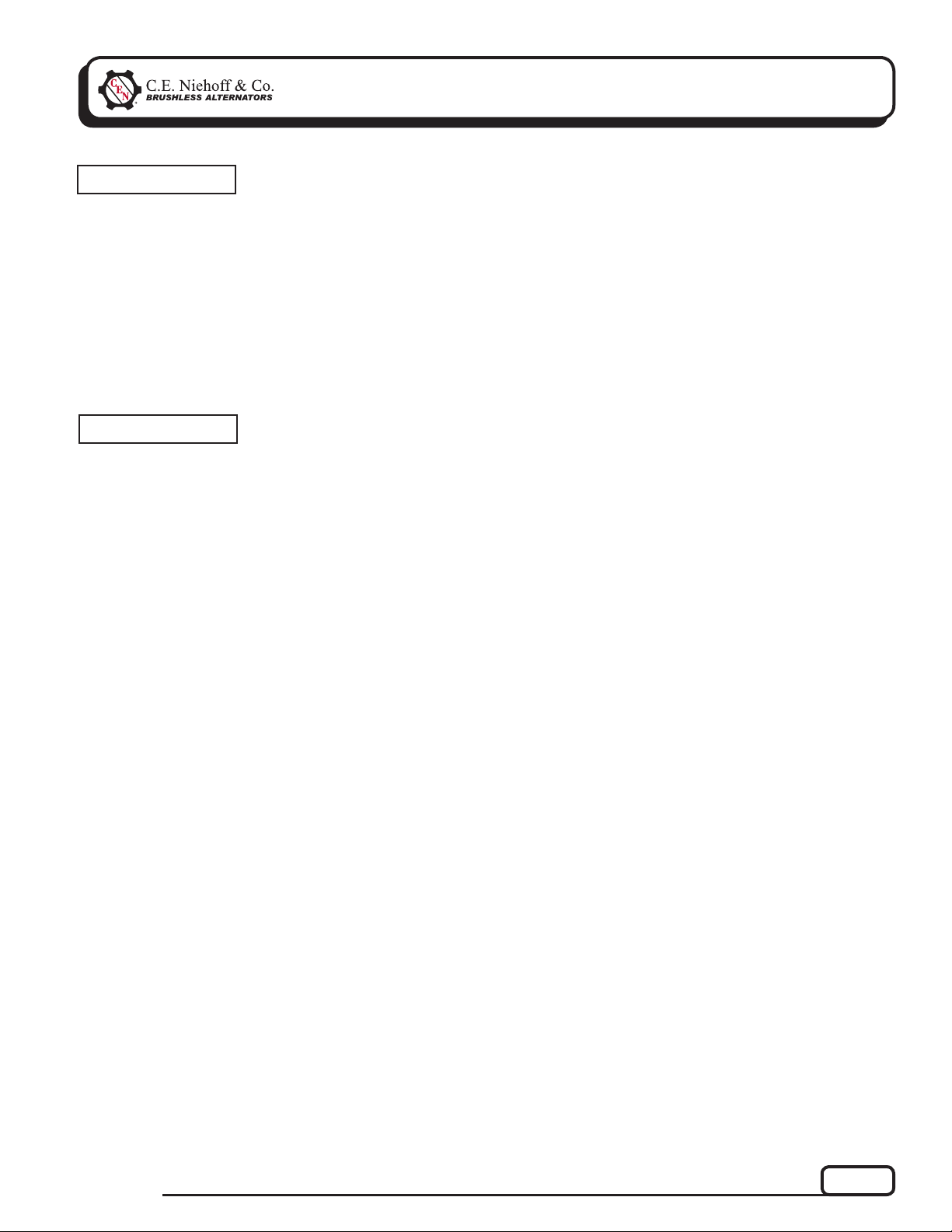
System #2 connection
Alternator connection
System #1 connection
Ground bolt
Figure 1 – N2013 Battery Isolator
Section B: Basic Troubleshooting
Tools and Equipment for Job
• Digital Multimeter (DMM)
• Ammeter (digital, inductive)
• Jumper wires
Basic Troubleshooting
1. Inspect charging system components
Check connections at ground cables, positive
cables, and regulator harness. Repair or replace
any damaged component before troubleshooting.
2. Inspect N2013 battery isolator connections
Connections must be in proper sequence and
clean and tight.
3. Inspect connections of vehicle batteries
Connections must be clean and tight.
4. Determine battery type, voltage, and state
of charge
Batteries in each bank must be all the same type
for proper system operation. If batteries are
discharged, recharge or replace batteries as neces sary. Electrical system cannot be properly tested
unless batteries are charged 95% or higher.
See page 1 for details.
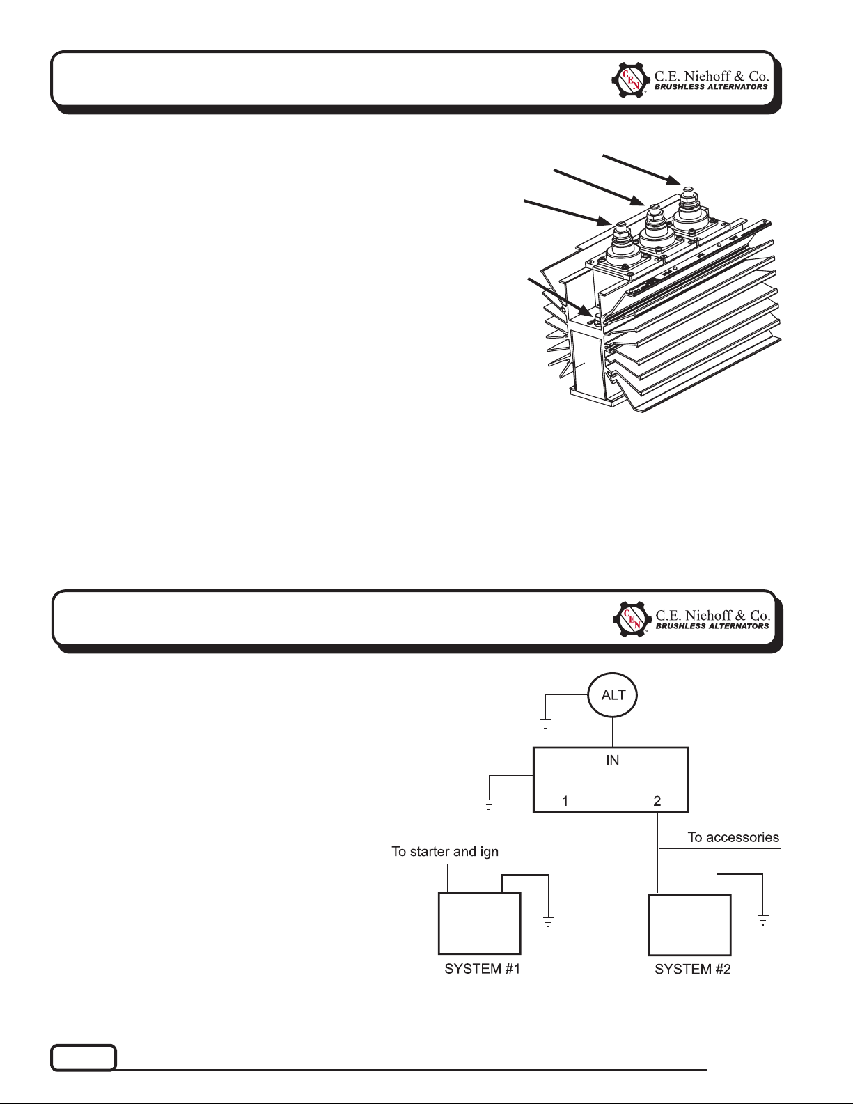
Figure 2 - Generic Wiring Schematic for Reference Only—
See Vehicle Manufacturer Specifi cations
Page 2
TG0055A
Page 3

Section C: Advanced Troubleshooting
Chart 1 – No Power to System #1 or #2 with Engine Running
Before Troubleshooting, Check Batteries for Proper Charge Voltage. See Page 1.
Disconnect battery master switches.
Check for 0.1 V diode voltage drop between System 1 terminal on isolator and alternator terminal
on isolator. Then check for 0.1 V diode voltage drop between System 2 terminal on isolator and
alternator terminal on isolator.
Does the voltage drop exist at each set of tests?
Yes
T
Go to alternator troubleshooting
guide to troubleshoot alternator
and regulator.
No
T
Battery isolator
is defective.
If you have questions about your alternator or a ny of these test proce dures, or if you need to locate a Factory Authorized Service Dealer, please contact us at:
C. E. Niehoff & Co.• 2021 Lee Street • Evanston, IL 60202 USA
TEL: 800.643.4633 USA and Canada • TEL: 847.866.6030 outside USA and Canada • FAX: 847.492.1242
E-mail us at service@CENiehoff.com
TG0055A
Page 3
 Loading...